Panhard 2012 Engine Repair
22/09/14 10:20 Filed in: Panhard Engine
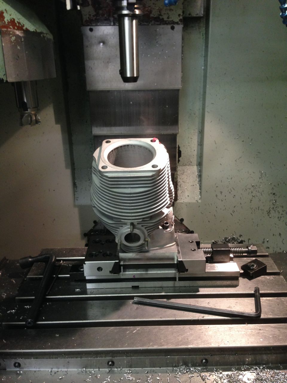
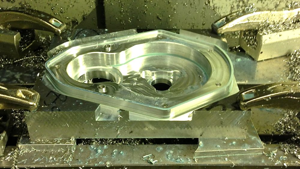
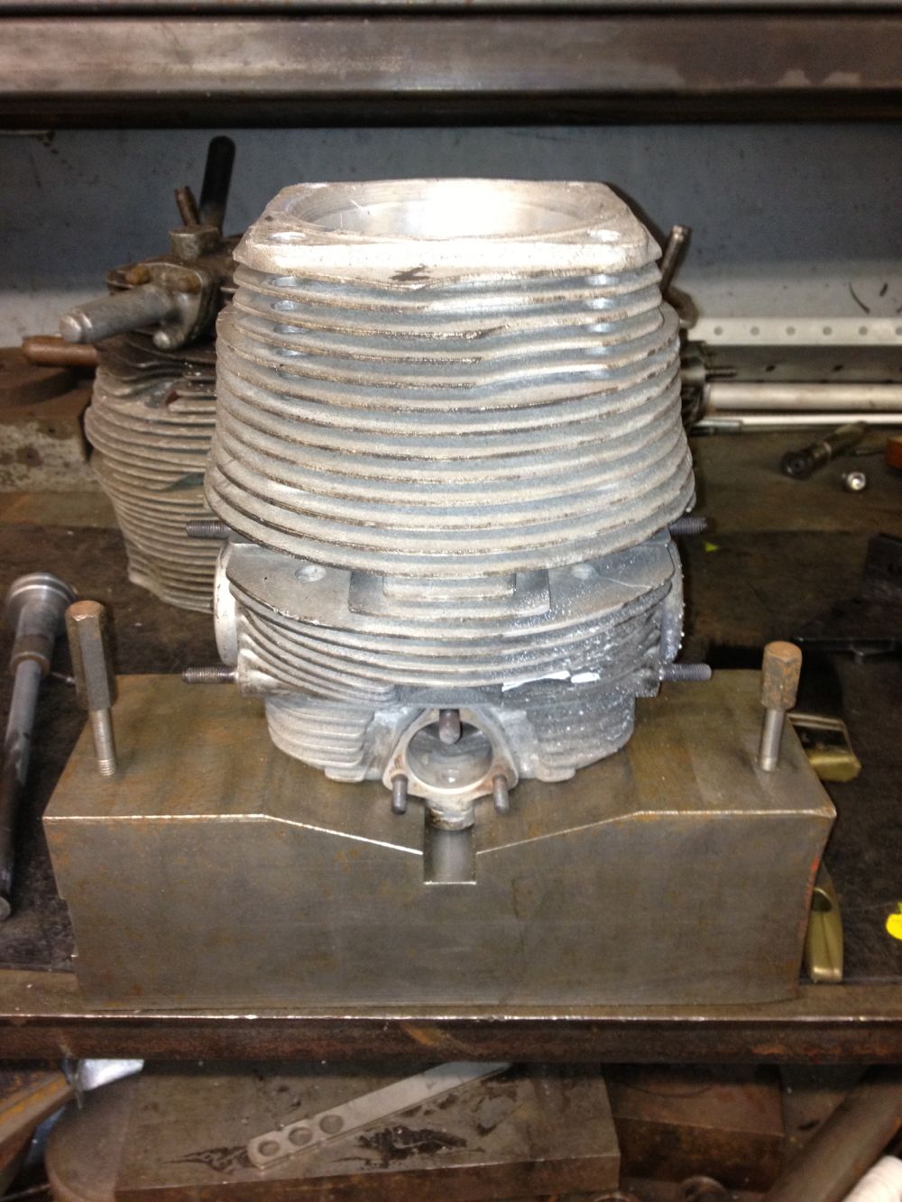
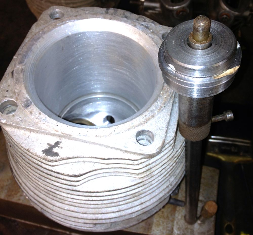
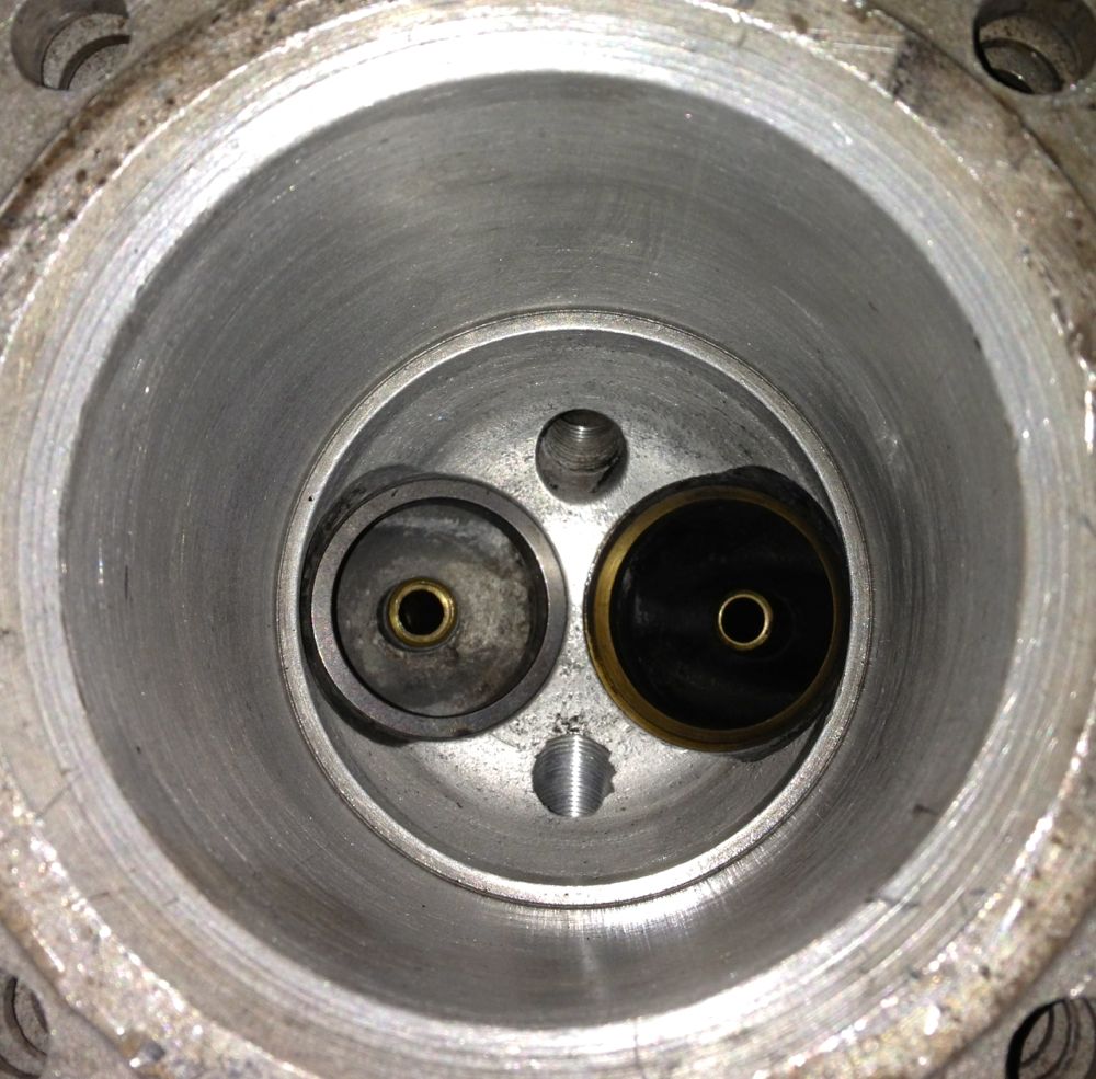
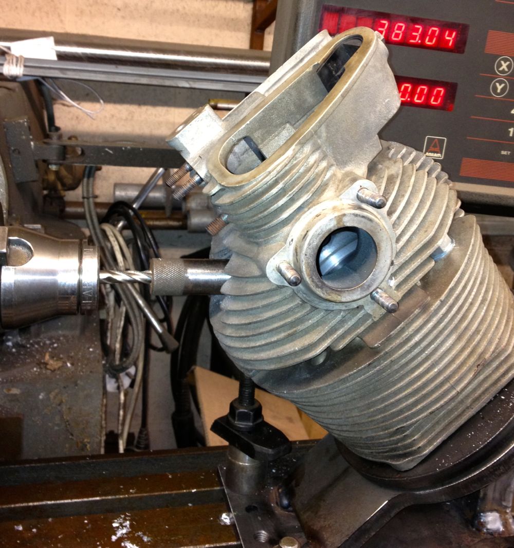
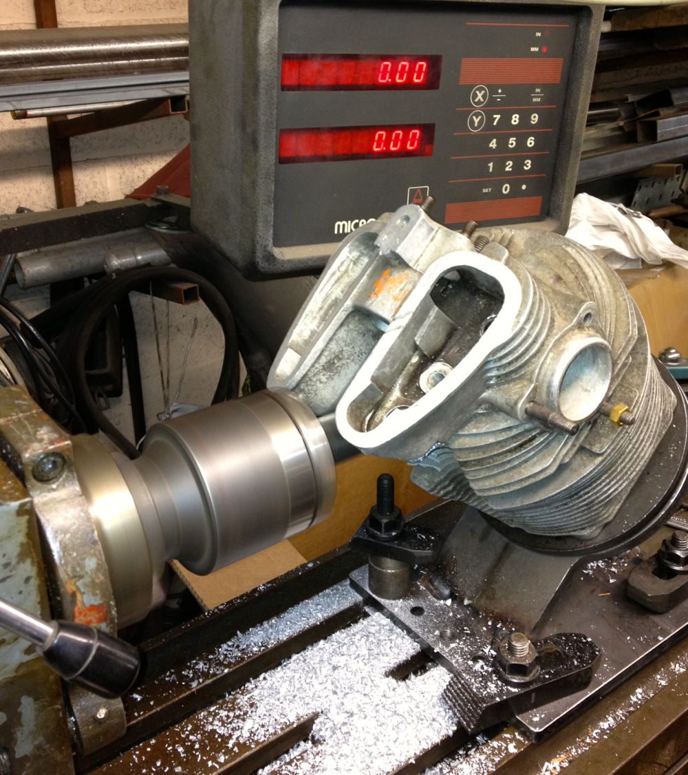
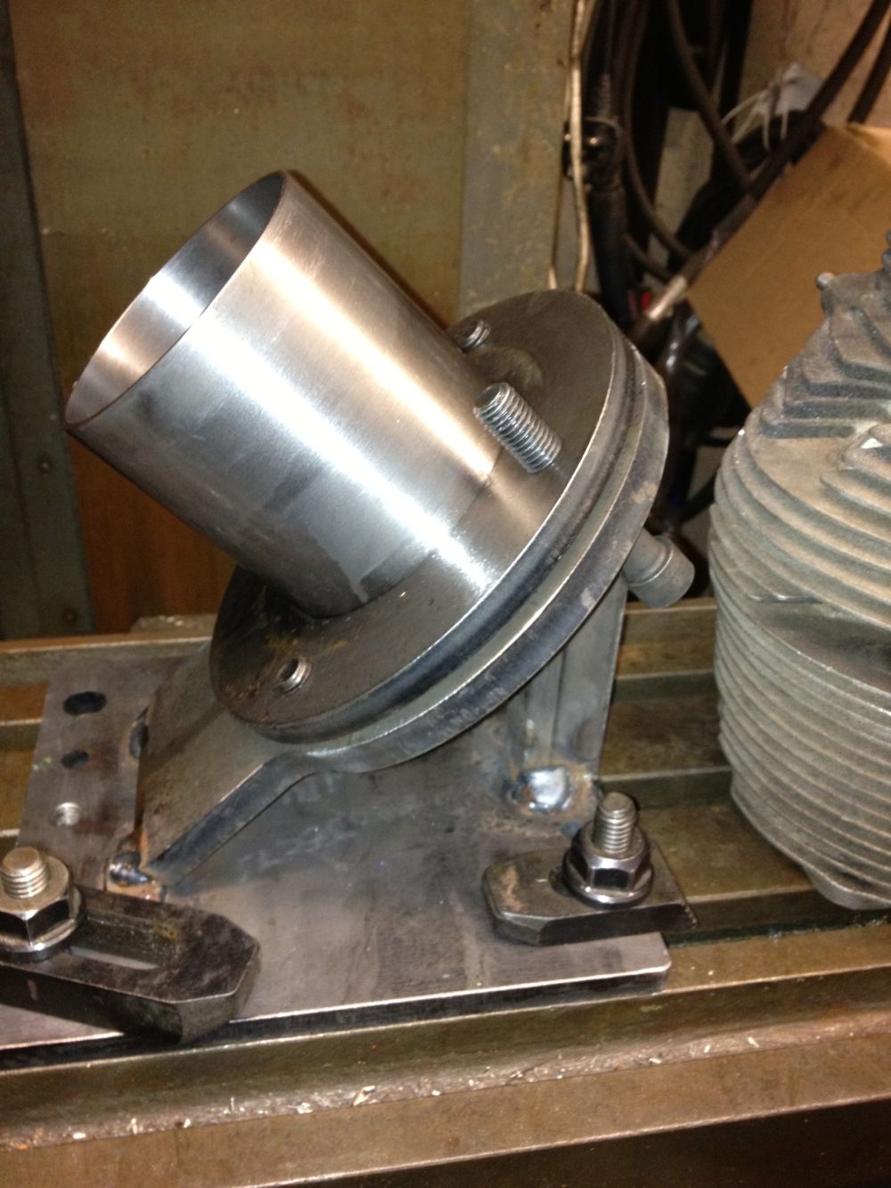
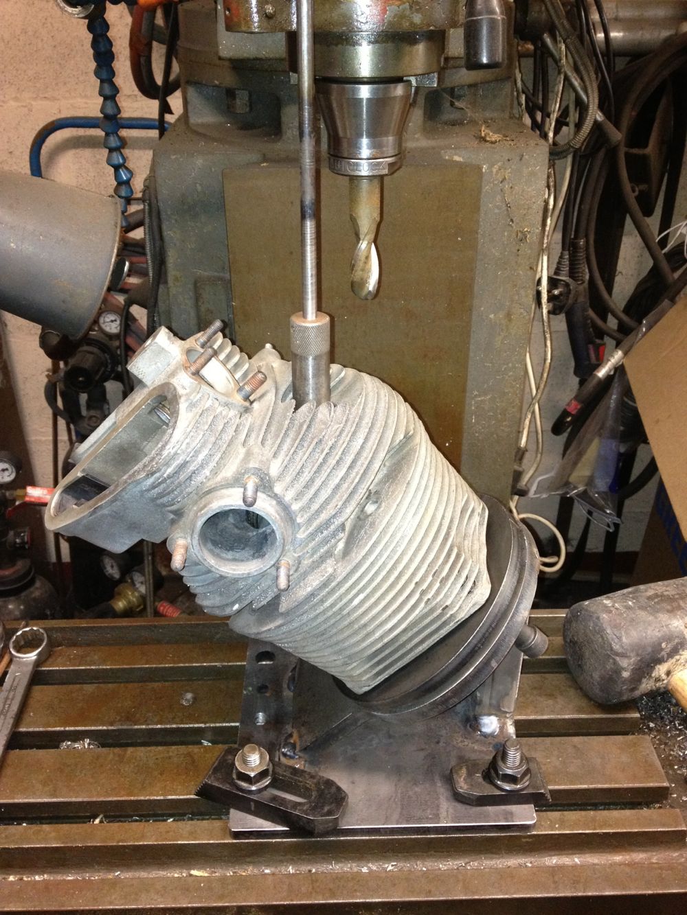
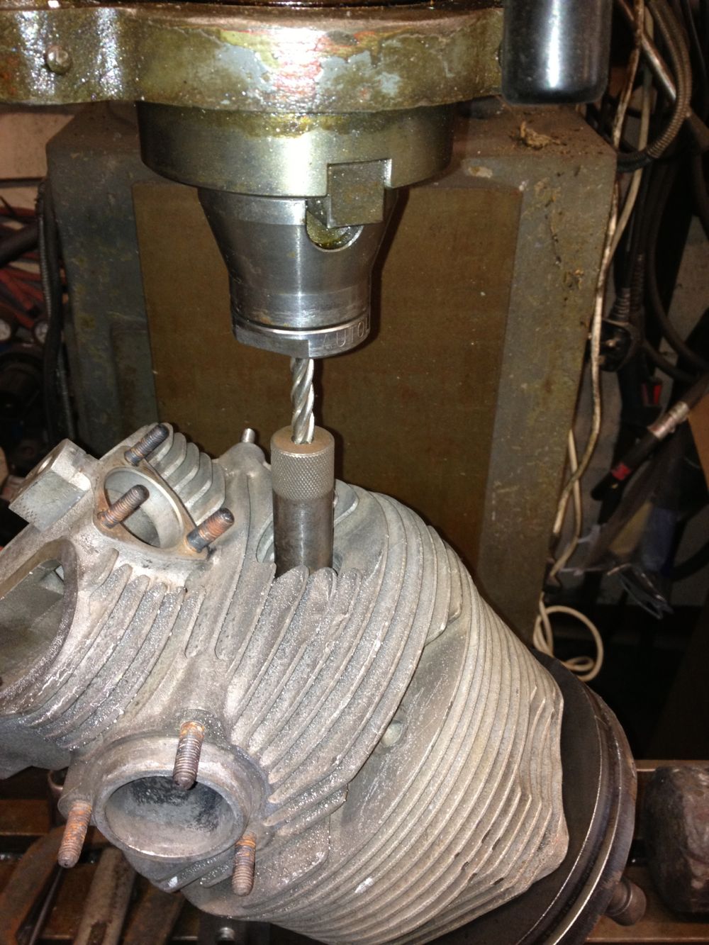
Finally the wait is over, and I have realised the cylinder jig. This is the first attempt, at making a multi purpose jig that can hold the cylinder in three positions, one for the exhaust valve rework, and another for the inlet valve, with the middle position being the overbore and combustion chamber rework for the larger capacity engine.
It was fitted to the larger CNC mill today for a test fit, and make sure the extended tooling didn’t catch the walls of the standard cylinder. To machine the valve seats I need a special carbide tipped tool about 30mm or so diameter, so that the tool spindle doesn’t catch the sides.
It was fitted to the larger CNC mill today for a test fit, and make sure the extended tooling didn’t catch the walls of the standard cylinder. To machine the valve seats I need a special carbide tipped tool about 30mm or so diameter, so that the tool spindle doesn’t catch the sides.
Comments
Panhard 2012 Engine Installed Part 1
14/05/13 20:18
Over the course of the day, the 2012 engine is getting installed in Brian’s car
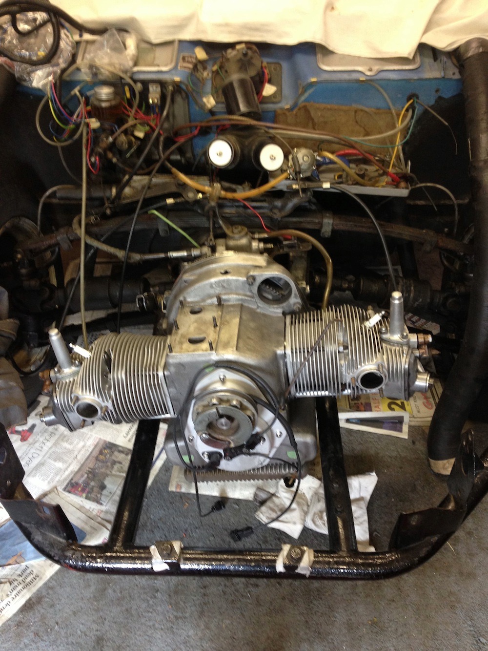
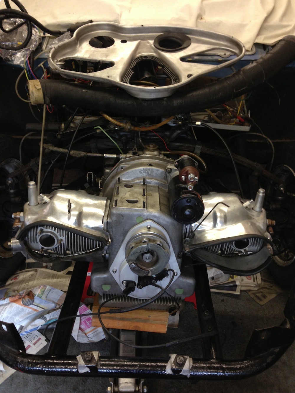
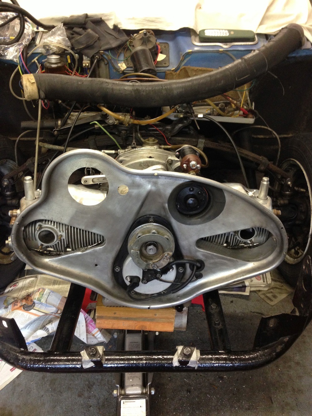
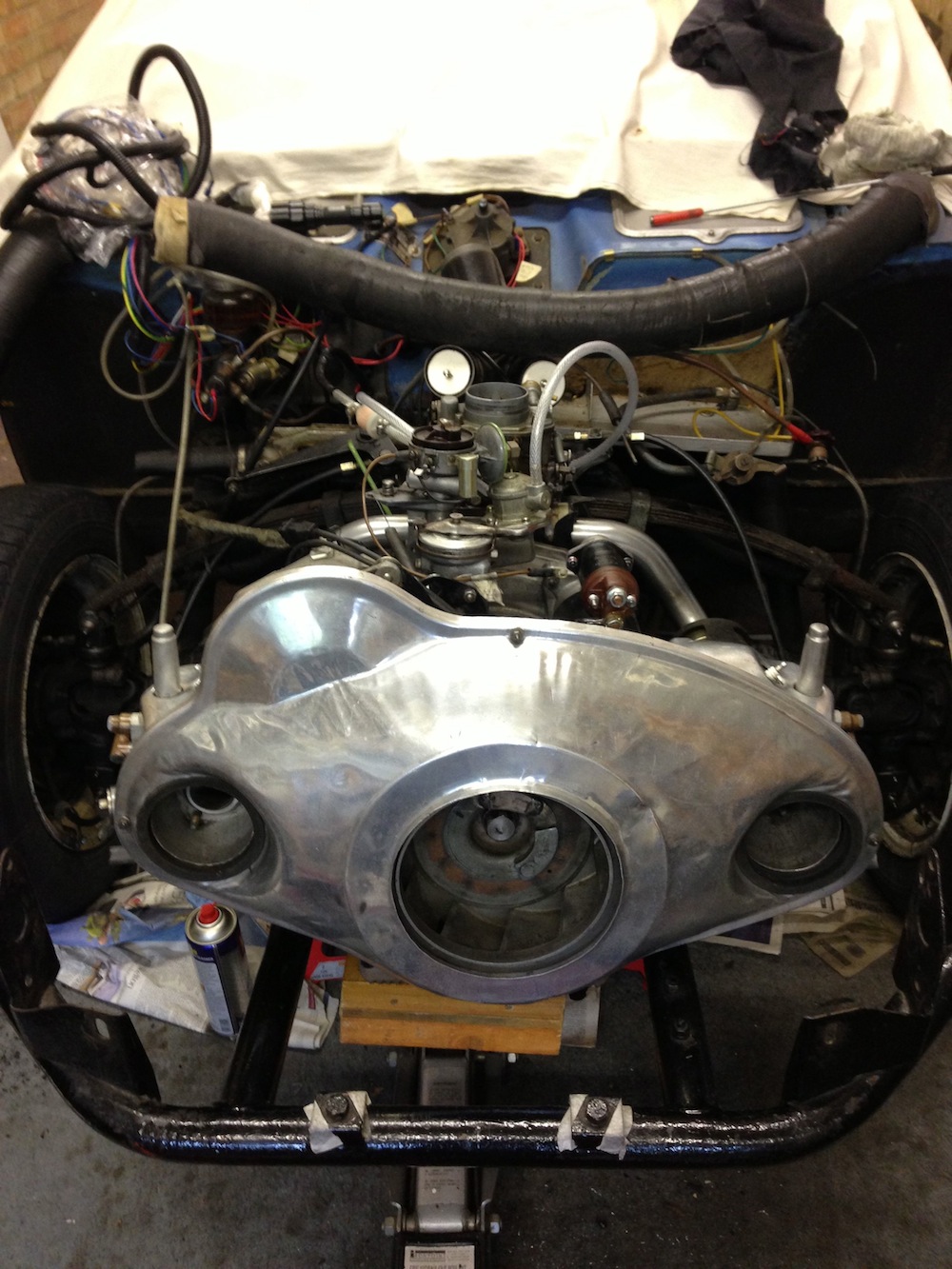
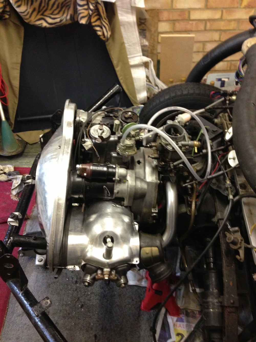
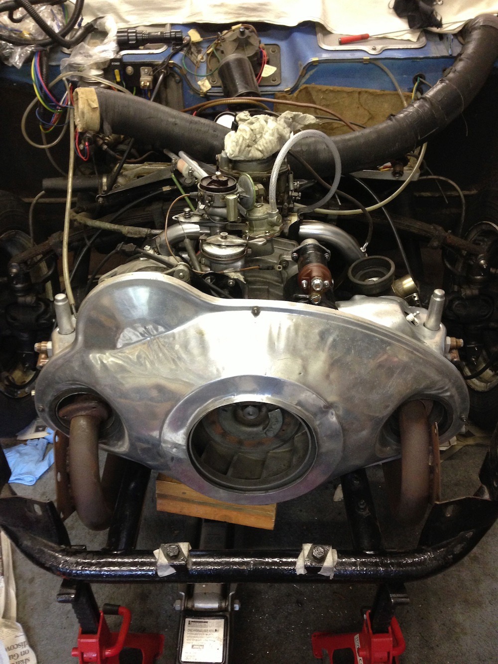
Exhausts not fastened up yet, and no wiring. MOT booked for 14:00, which might be a tad optimistic!
Exhausts not fastened up yet, and no wiring. MOT booked for 14:00, which might be a tad optimistic!
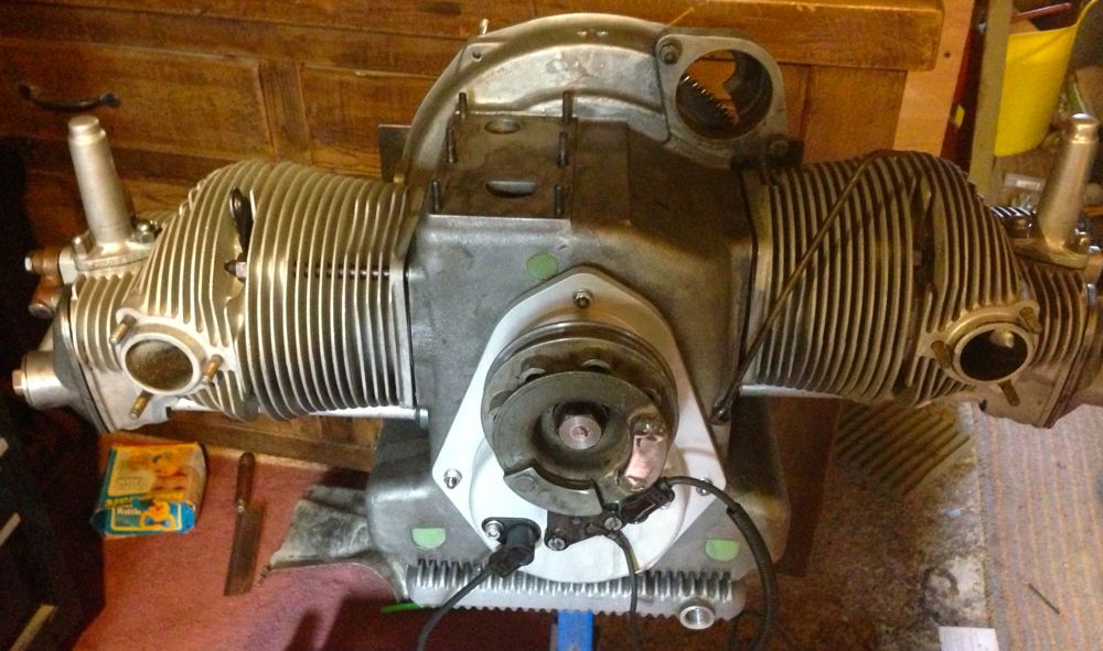
Panhard 2012 Engine Assembled
13/05/13 16:45 Filed in: Panhard Engine
I have just finished the assembly of Brian’s engine, aka the 2012 engine. As the deadline approached and some pieces became unavailable (crankshaft issues forced the changes), the planned developments changed and Brian’s engine now includes
JE higher compression pistons,
New redesigned cylinder liners with revised tolerances.
Modified porting to inlet & exhaust
Recut & re-profiled valve seats
Peter Breed Rallye Crankshaft
Peter Breed lightened flywheel and clutch assembly
Revised oil circuits
Greater oil capacity by fitting M. Joel Brunel’s double sump (modified to take O ring seals & filter plate)
New & bespoke second generation Internal oil filter (Yamaha motorcycle)
Viton oil seal to rear crankshaft bearing
Viton oil seal to front bearing
CNC alloy front timing cover incorporating ignition sensors.
Imfsoft IgnitionTCI 6.1 Programmable Ignition
Twin plugged cylinders with Bosch Twin Single Fire Coils
MAP sensor
So hopefully in a few days, it’ll be Almen here we come.
Panhard Front Timing Cover, Revised again & updated
07/05/13 21:45 Filed in: Panhard Engine | Panhard Ignition
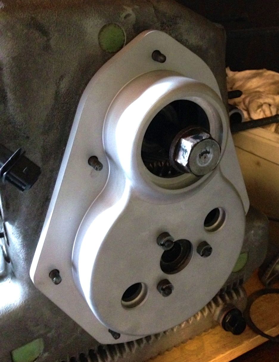
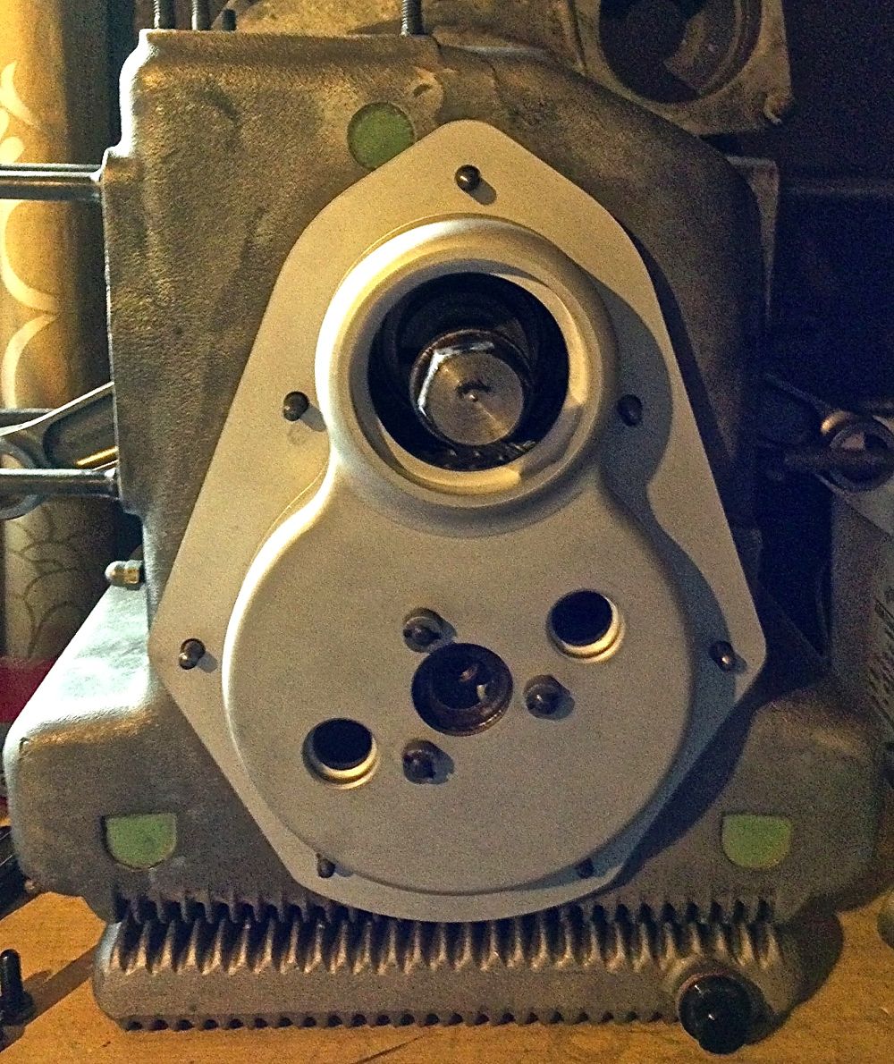
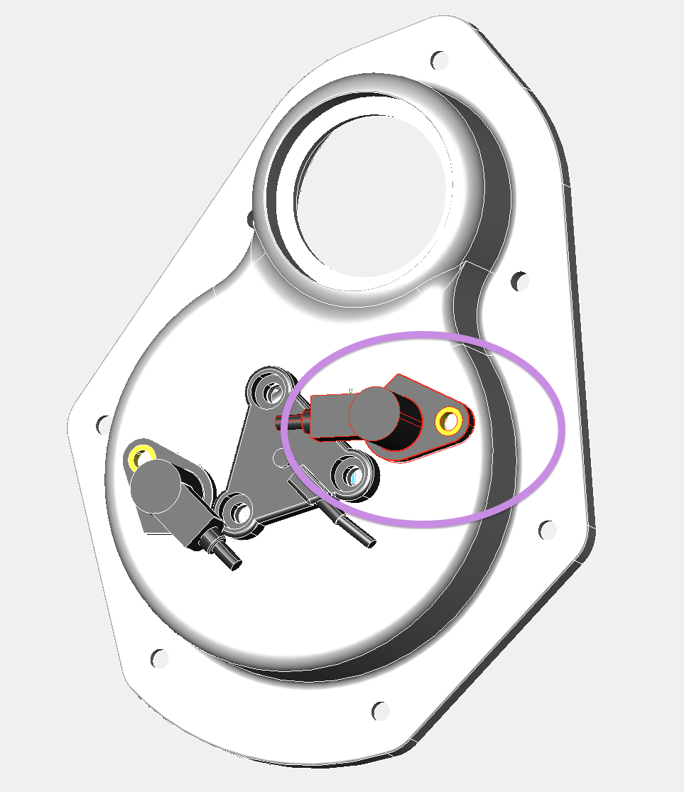
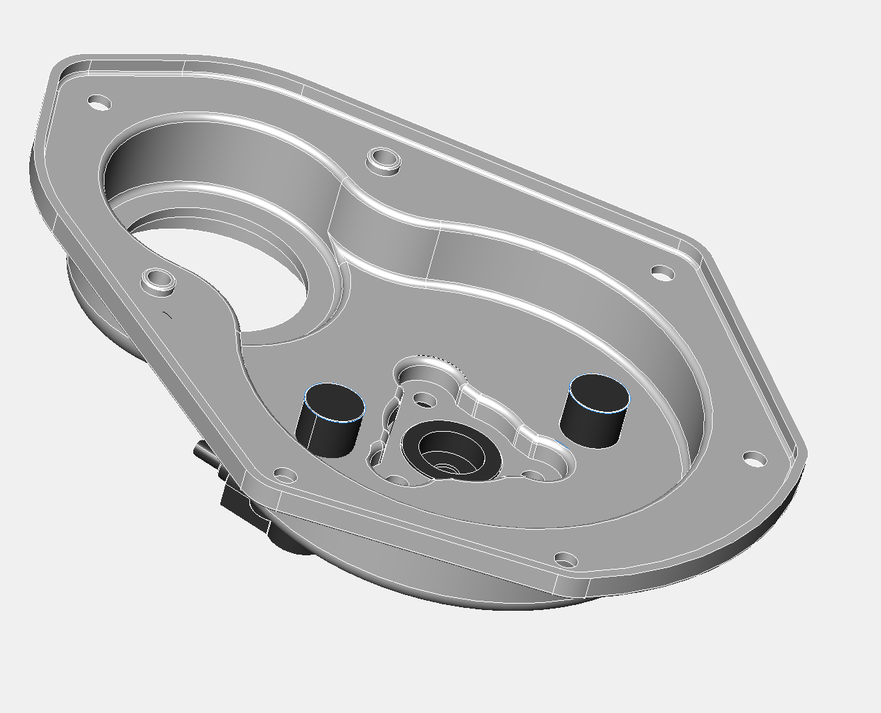
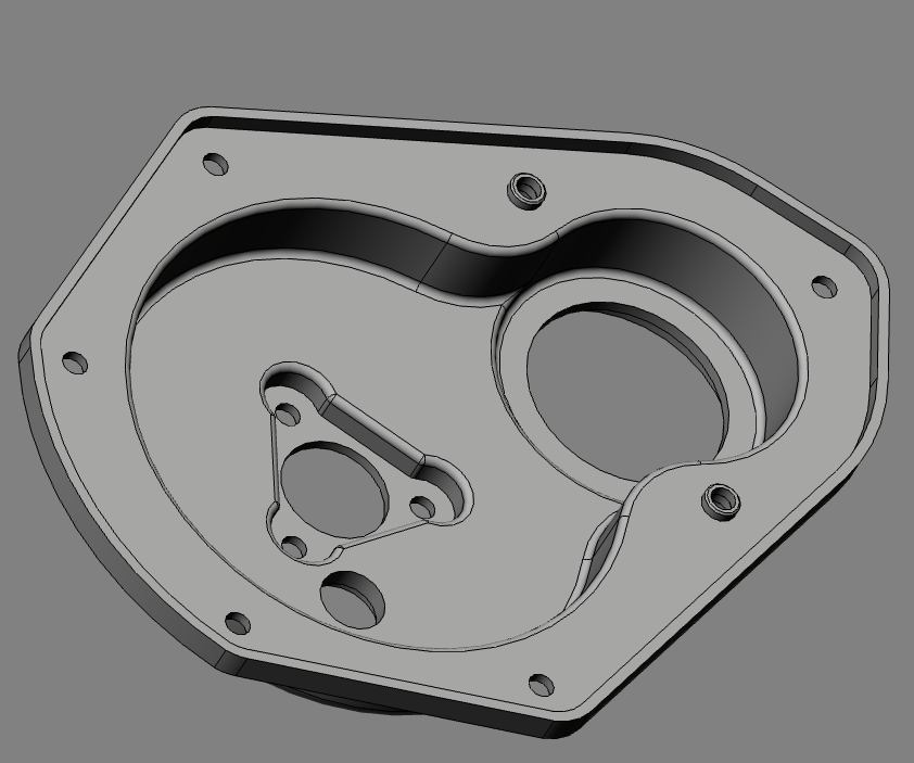
So I got the modded cover back tonight, and after testing the clearances at the oil light switch and the sensor to fan, I realised that the first batch need another tweak, but that’ll have to do for the next batch.
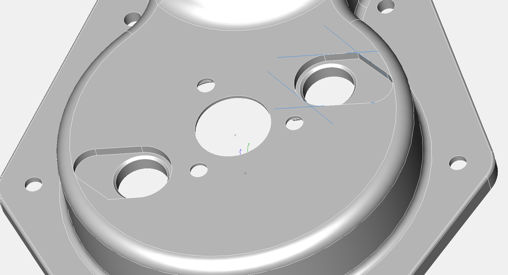
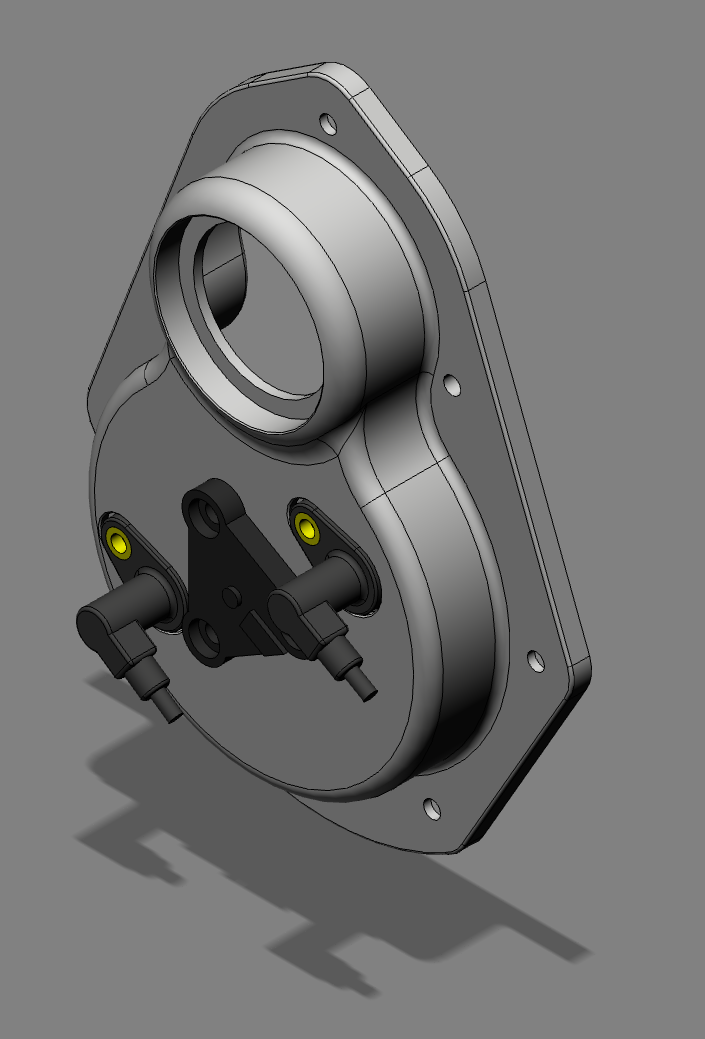
I have simplified the sensor through hole (pictured above), and recessed the sensor by another millimetre for this batch. The oil light internal depth is as far machined as I can go, and ideally needed another millimetre here, so I modded my oil light piston, essentially just making it shorter. Nothing is bolted down in the pictures, as I am just testing the fit, although I did use a multimeter to confirm the action of the oil light switch contacts.
Tomorrow, I’ll do a final test fit for the sensor body into the recessed area, and that’ll be that for this batch.
In the future I will tweak the design slightly, but that’ll be just for the oil light operation.
Panhard Front Timing Cover Sensor Fit & Update
05/05/13 18:59 Filed in: Panhard Engine | Panhard Ignition
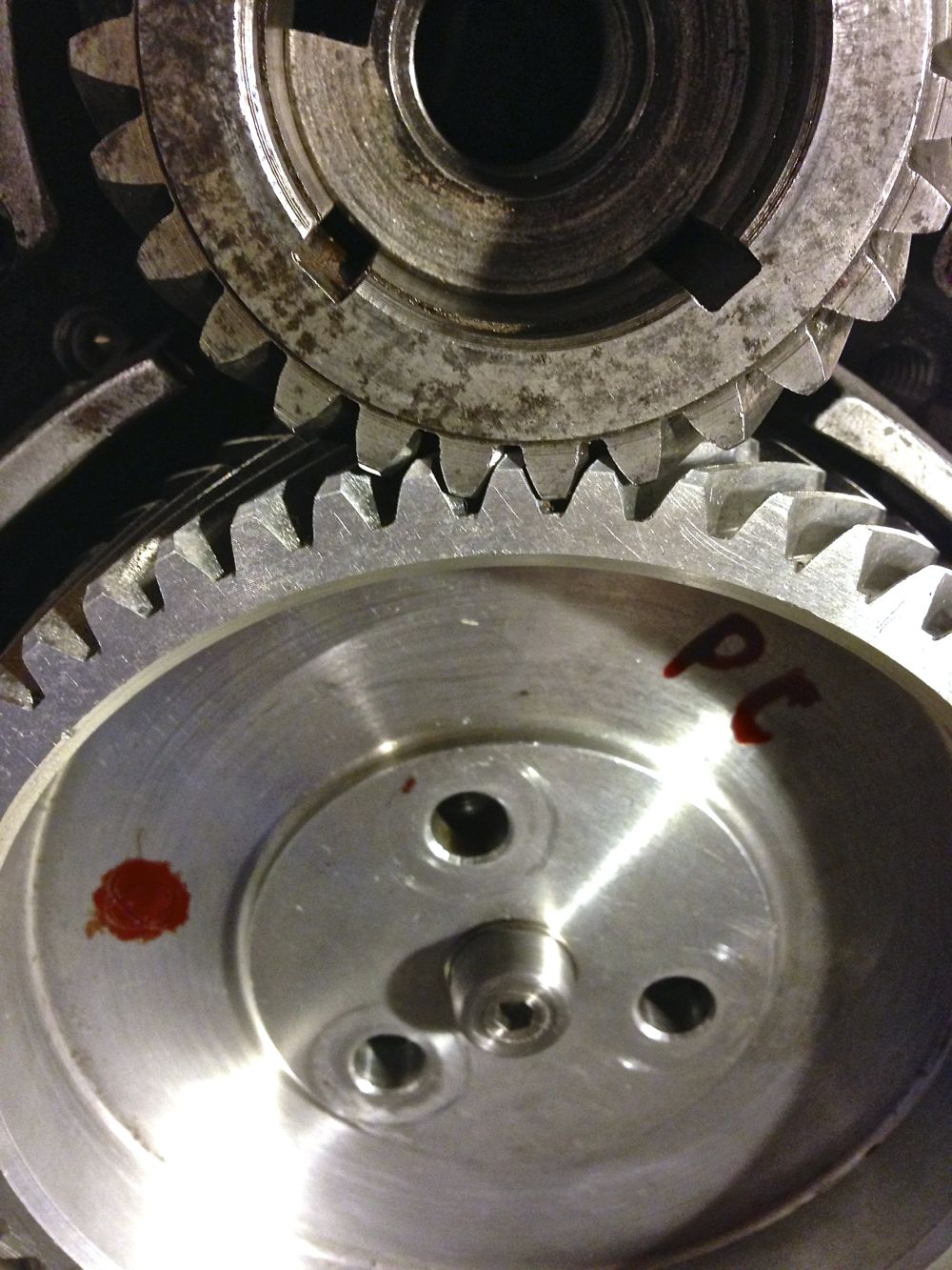
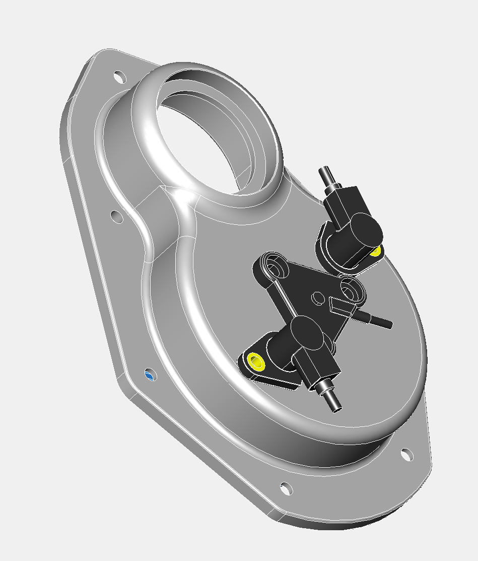
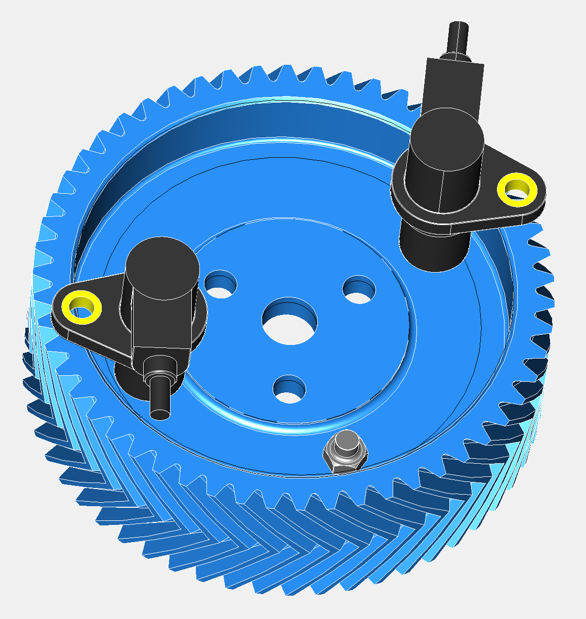
Last night I was sitting pretty, so to speak, but this morning I decided to fit the wooden blocks and springs to mount the front fan assembly and check the clearance on Brian’s engine. After torquing up the pulley centre bolt, I noticed a few millimetres of clearances, but on rotating the turbine or fan, it scraped the top of the sensor.
I have never seen a misshaped turbine before, so I tried several different ones I had lying around, and surprisingly they were all misshaped, with the resultant wobbling just catching the top of the sensor at some point, so obviously more clearance was needed.
I had two options change the sensor, or recess the sensor some more, and as all my work on the sensor was completed and it is a cost effective (aka cheap) solution with excellent sensitivity, I was reluctant to change the former. This meant recessing the sensor into the timing cover. As I looked at this, I thought I’d check the oil light function, and this too was just too tight a fit, such that the oil light would never illuminate, which isn’t a bad thing, but it isn’t how I intended things to operate.
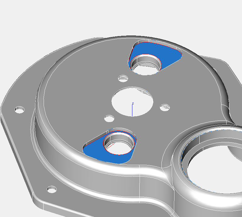
So a quick 3D tweak was in order, and this has been passed onto the 3D CNC fabricator. Slightly annoying for him, but better for us all. Oil light switch surface has been reduced in thickness (blue area) in the picture below, and below this the recessed area to add more sensor to turbine clearance. Not quite as elegant as I’d like, but it’ll do for now, and after testing there might be a slight refinement for the next batch.
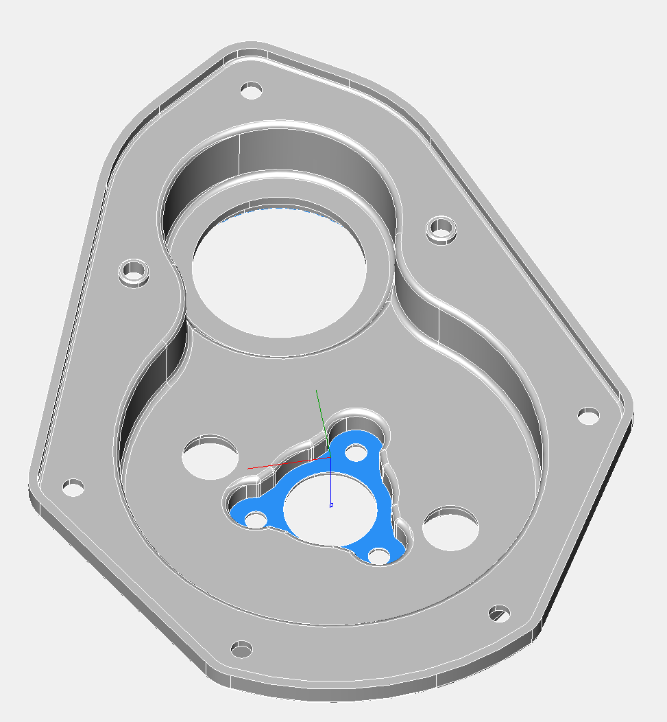
PS I thought I would weigh this part, and check the calculated weight in the CAD model versus the actual weight. The CAD model suggested 719 grams, but the actual weight was 723 grams, which is pretty close, and well within 1%. Incidentally, the standard part weighed around 530 grams, but this new timing cover is considerably thicker in places.
I have never seen a misshaped turbine before, so I tried several different ones I had lying around, and surprisingly they were all misshaped, with the resultant wobbling just catching the top of the sensor at some point, so obviously more clearance was needed.
I had two options change the sensor, or recess the sensor some more, and as all my work on the sensor was completed and it is a cost effective (aka cheap) solution with excellent sensitivity, I was reluctant to change the former. This meant recessing the sensor into the timing cover. As I looked at this, I thought I’d check the oil light function, and this too was just too tight a fit, such that the oil light would never illuminate, which isn’t a bad thing, but it isn’t how I intended things to operate.
So a quick 3D tweak was in order, and this has been passed onto the 3D CNC fabricator. Slightly annoying for him, but better for us all. Oil light switch surface has been reduced in thickness (blue area) in the picture below, and below this the recessed area to add more sensor to turbine clearance. Not quite as elegant as I’d like, but it’ll do for now, and after testing there might be a slight refinement for the next batch.
PS I thought I would weigh this part, and check the calculated weight in the CAD model versus the actual weight. The CAD model suggested 719 grams, but the actual weight was 723 grams, which is pretty close, and well within 1%. Incidentally, the standard part weighed around 530 grams, but this new timing cover is considerably thicker in places.
Panhard Front Timing Cover Sensor Fit
04/05/13 18:33 Filed in: Panhard Ignition | Panhard Engine
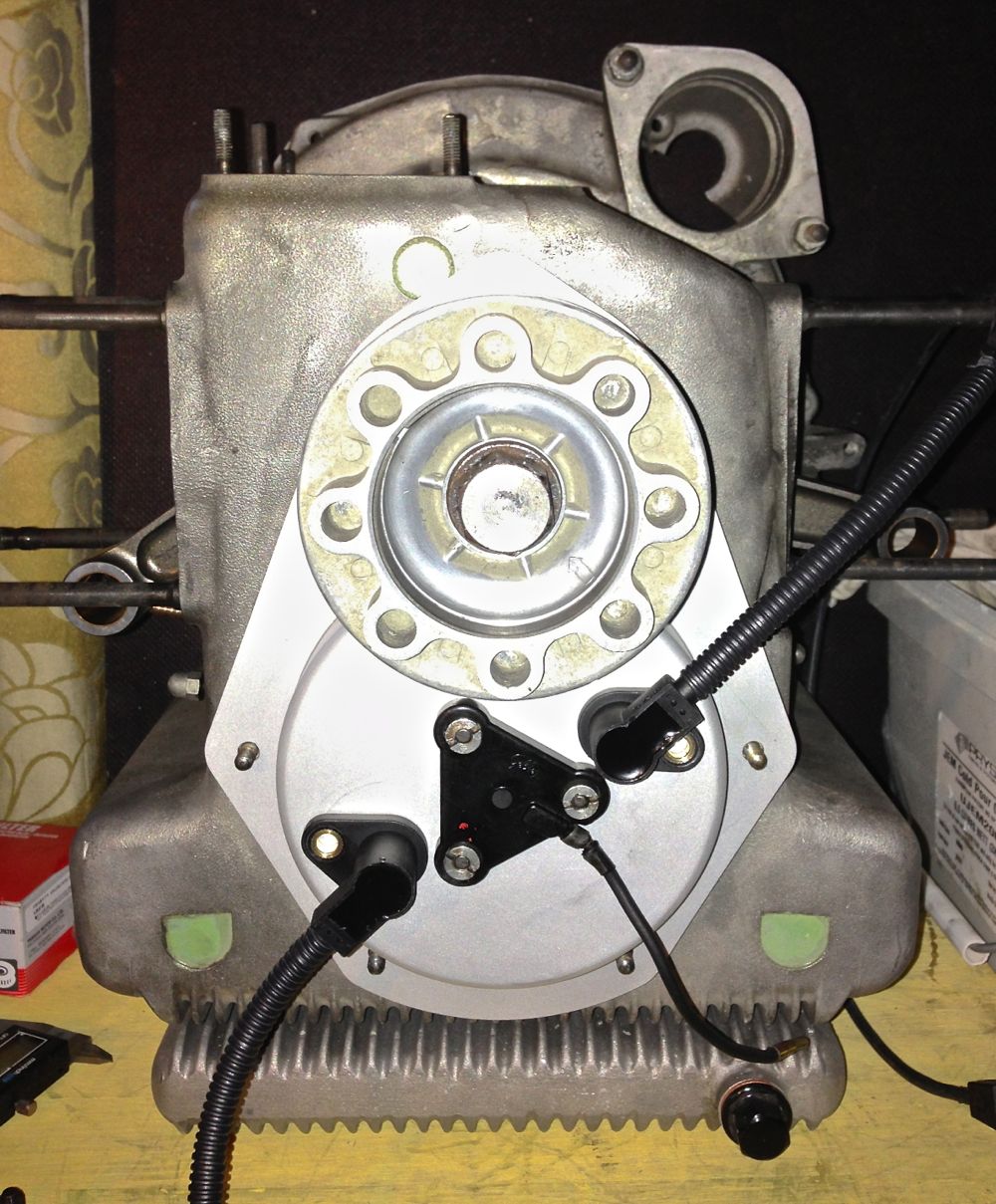
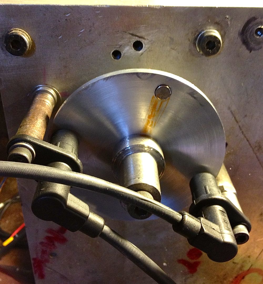
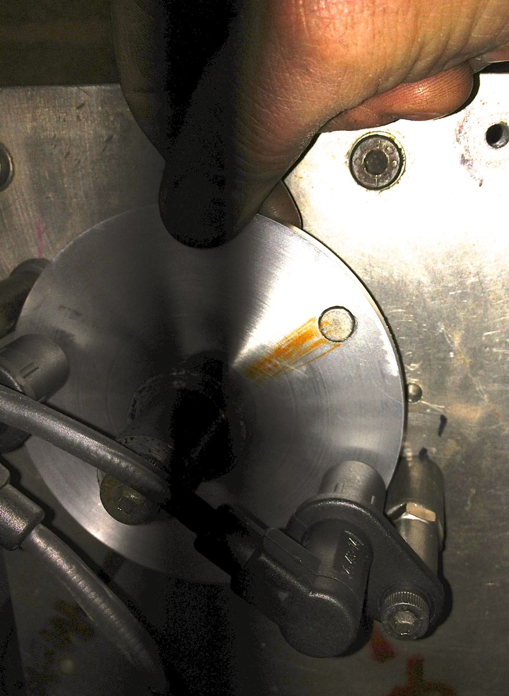
I noticed when I was testing the sensors that these parts are orientation sensitive, so I created an orientation map to help me when it came to fitting the sensors.
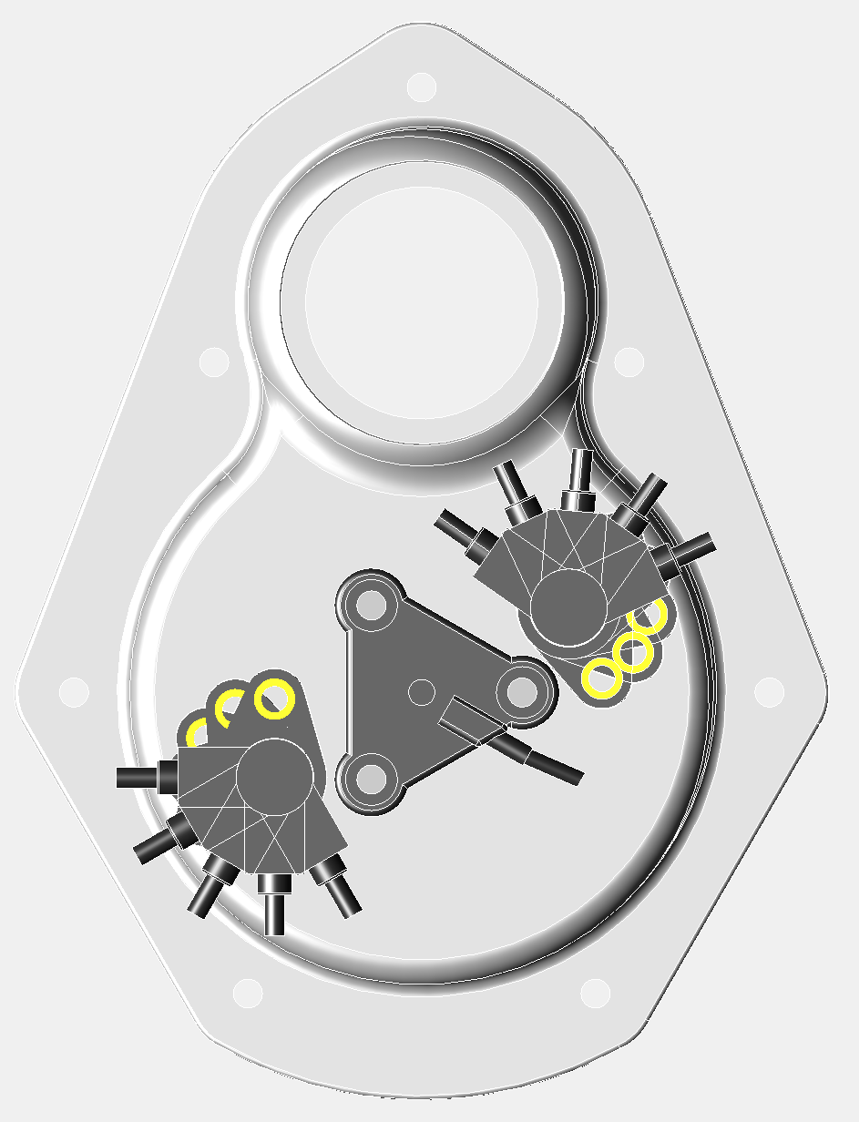
It was just a s well, because when I fitted the crankshaft pulley, I noticed the right hand sensor had very few options. The cable will foul the pulley, unless it is in the 1 or 2 o’clock positions, and it is best if it is tangental to the pulley, as this gives more room for dynamo V belt replacement. This is only really a consideration, as I am using sequential twin spark with the Imfsoft Ignition TCI module, and if I used a MicroSquirt, I could just use a single sensor and a toothed wheel. This will also be the case with electronic fuel injection too.
Notice how the Gelbey oil light sensor is rotated, which gives more clearance for sensor rotation.
Tangental orientation below.
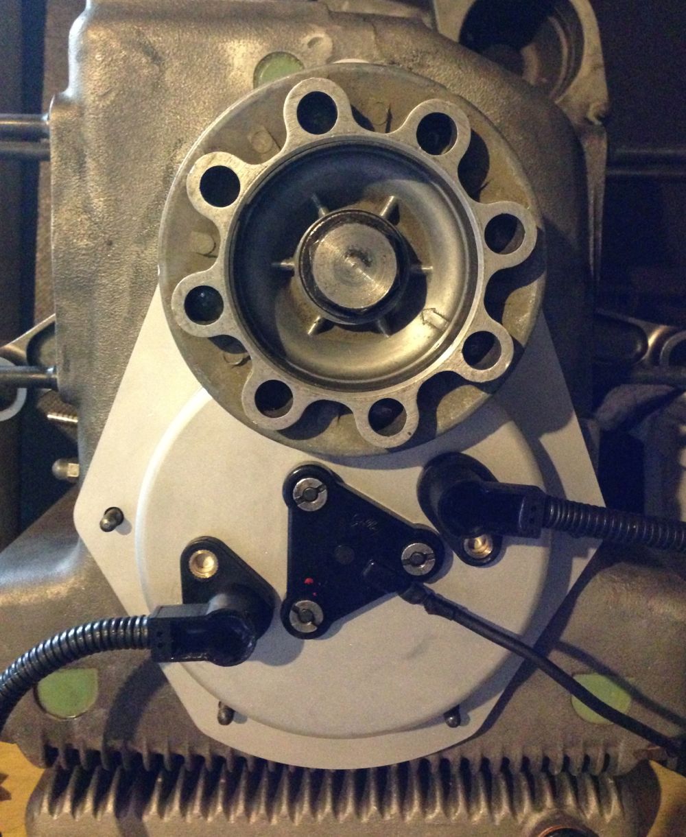
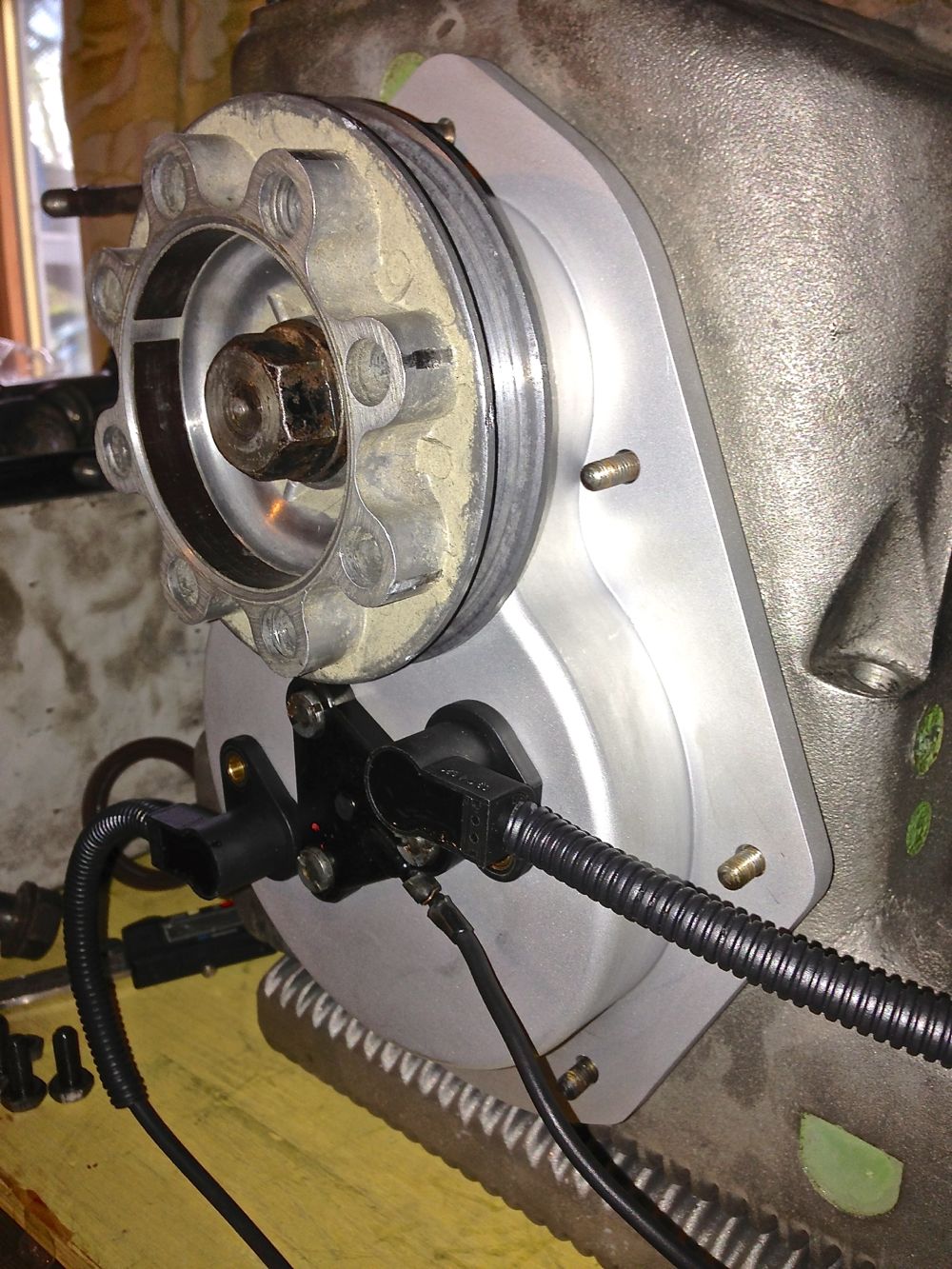
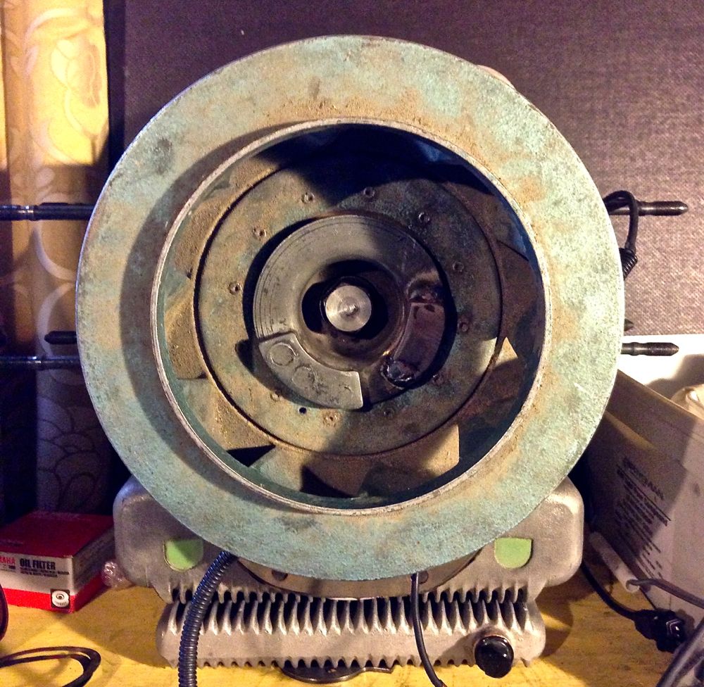
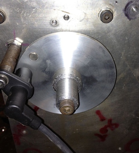
Next up was to check the cowling & fan fit
.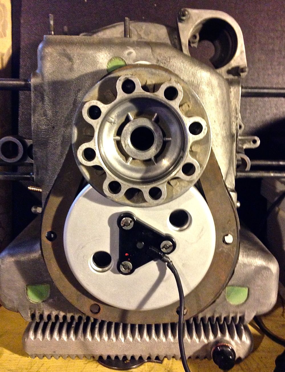
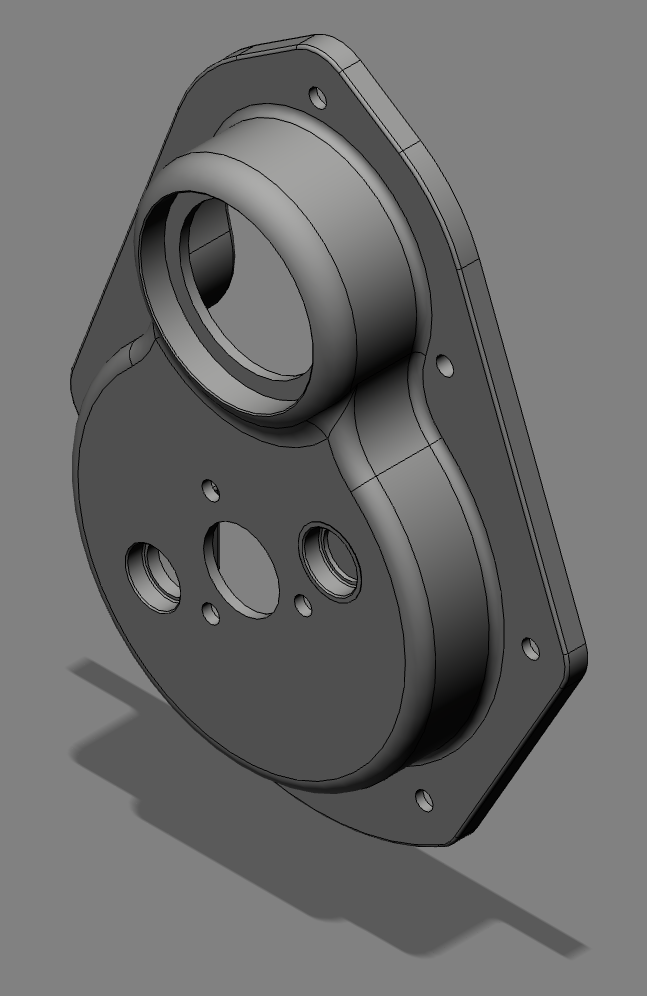
After this check the fan clearance, this is the front view, and how discreet is this cover. You wouldn’t realise it was there
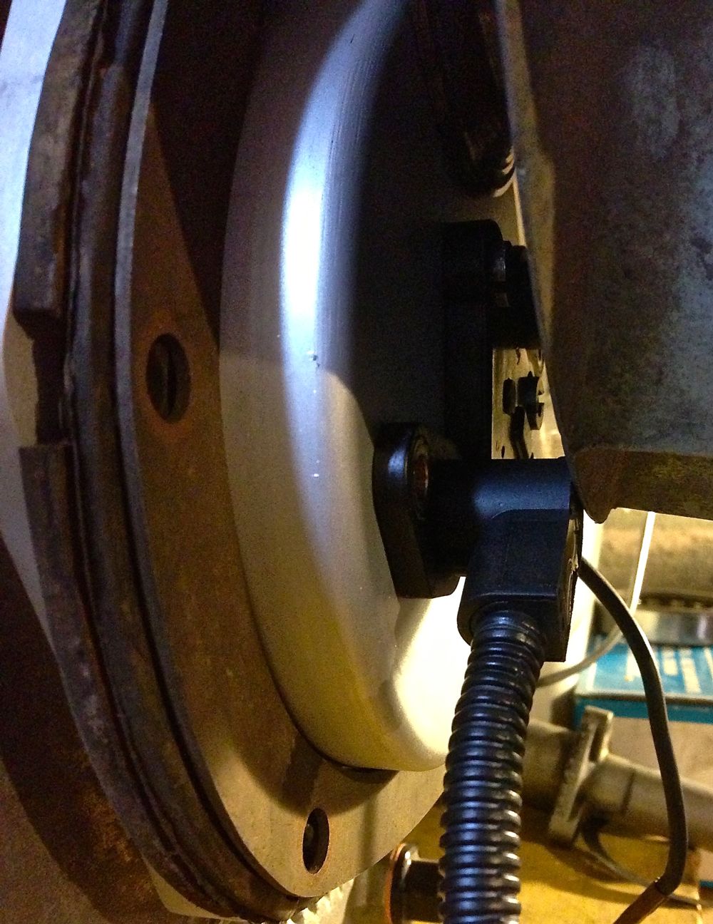
More importantly the clearance for the lower left hand sensor! Pretty tight, except the fan is pushed 5mm further forward if my measurements are right (phew)!
All in all, not a bad first stab, even if I do say so myself!
It was just a s well, because when I fitted the crankshaft pulley, I noticed the right hand sensor had very few options. The cable will foul the pulley, unless it is in the 1 or 2 o’clock positions, and it is best if it is tangental to the pulley, as this gives more room for dynamo V belt replacement. This is only really a consideration, as I am using sequential twin spark with the Imfsoft Ignition TCI module, and if I used a MicroSquirt, I could just use a single sensor and a toothed wheel. This will also be the case with electronic fuel injection too.
Notice how the Gelbey oil light sensor is rotated, which gives more clearance for sensor rotation.
Tangental orientation below.
Next up was to check the cowling & fan fit
.
After this check the fan clearance, this is the front view, and how discreet is this cover. You wouldn’t realise it was there
More importantly the clearance for the lower left hand sensor! Pretty tight, except the fan is pushed 5mm further forward if my measurements are right (phew)!
All in all, not a bad first stab, even if I do say so myself!
Panhard Front Timing Cover First Fit
04/05/13 12:43 Filed in: Panhard Engine | Panhard Ignition
Just a quick update again, as I have to jump on the lathe in a moment, more of a quick snap for Brian, as he’s got broadband now!
The first trial fit on a crankcase went exceptionally well, as the cover fits snuggly with no discernible play on the locating dowels.
There were two minor issues, one the oil light piston tab washer detail was slightly too small, and two, the O ring seal could be marginally tighter on the sensor holes, but all these have details have been corrected in the 3D model now, so the rest of this batch will be spot on.
I am extremely pleased with the results so far, and even better, there is sufficient room for the various trigger wheel configurations I have planned.
I will update the pictures again later.
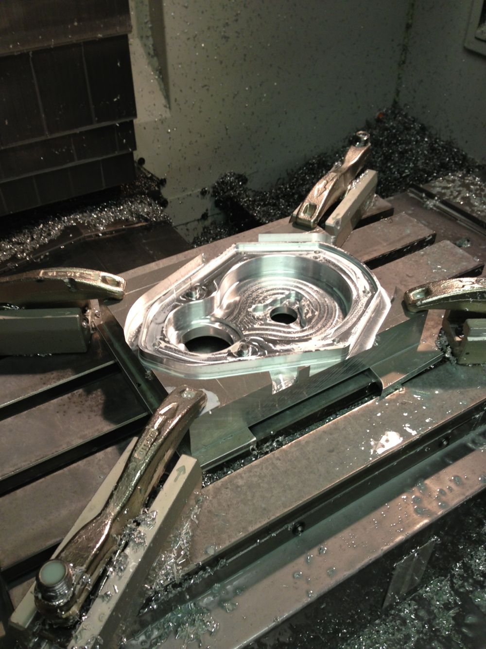
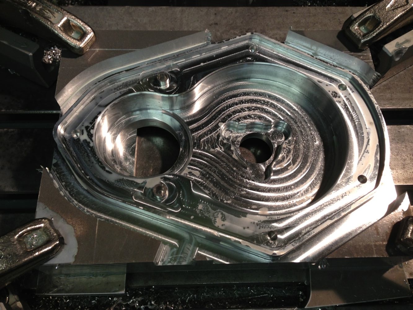
Panhard Front Timing Cover CNC Started
03/05/13 17:40 Filed in: Panhard Engine | Panhard Ignition
Panhard Rear Bearing Oil Seal Modification
30/04/13 22:17 Filed in: Panhard Engine
It was 10 years ago that I made a bespoke oil seal conversion for the rear bearing carrier using a small 55x63x5 Viton seal, and I was intending to use this on Brian’s engine. However, as I am close to the lathe it’s relatively easy to modify the rear carrier.
Brian’s original carrier was chewed by something since its last rebuild, so I couldn’t fit the rear seal mod that I designed, and was planning on using another one from my parts bin. Today, I decided I would machine the damaged portion away, and rather than use a 70mm seal, I opted to use a 72mm variant, which meant all the remnants of the SIMRIT oil channel could be removed, and leave a plain seal surface, as shown in the photo below.
I chose the 55x72x8 seal, because it was available in Viton & as a R23 variant, R23 means it has a dust seal too, but this is opened up after a short time anyway, but Viton is necessary because of the highish temperature and seal tip rotational speed.
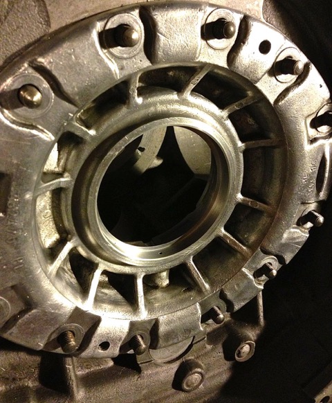
I also cleaned up the oil hole, adding a larger internal radius and opening up the oil supply hole to match the front.
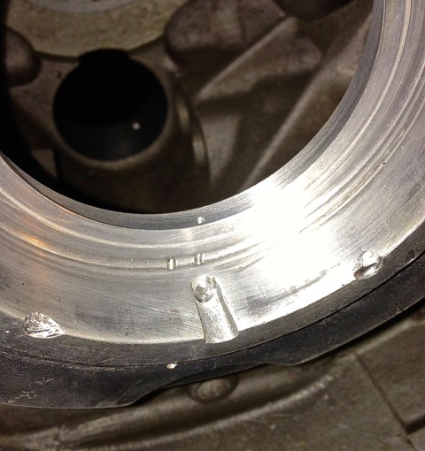
In the future, I will be doing this to all my engines, unless asked not to do so, but please note, I have no need to use a cast iron rear bearing carrier, as contrary to some beliefs, it is actually inferior, and a retrograde step to use it instead of the aluminium one.
Brian’s original carrier was chewed by something since its last rebuild, so I couldn’t fit the rear seal mod that I designed, and was planning on using another one from my parts bin. Today, I decided I would machine the damaged portion away, and rather than use a 70mm seal, I opted to use a 72mm variant, which meant all the remnants of the SIMRIT oil channel could be removed, and leave a plain seal surface, as shown in the photo below.
I chose the 55x72x8 seal, because it was available in Viton & as a R23 variant, R23 means it has a dust seal too, but this is opened up after a short time anyway, but Viton is necessary because of the highish temperature and seal tip rotational speed.
I also cleaned up the oil hole, adding a larger internal radius and opening up the oil supply hole to match the front.
In the future, I will be doing this to all my engines, unless asked not to do so, but please note, I have no need to use a cast iron rear bearing carrier, as contrary to some beliefs, it is actually inferior, and a retrograde step to use it instead of the aluminium one.
Panhard Front Timing Cover Modifications 5
14/04/13 10:13 Filed in: Panhard Engine | Panhard Ignition
I was burning the midnight oil last night, and I realised I made a mistake in drawing the crankshaft sensor, because it wasn’t the right shape. Ordinarily this wouldn’t have mattered, but the crankshaft sensor is rotation sensitive, and after double checking my bench rig, and mimicking the 3D CAD model positions on this, I found the error with the cable output.
The sensors can be deliberately rotated on the first batch of covers, as I will be drilling and tapping the M6 fixing screws to maximise trigger detection, but for the next generation of covers they will all be fully finished. I have tried to make the measurements as accurate as possible, but I expect this prototype cover might need a slight dimensional tweak for the second batch.
I have also made a decision to make the first batch twin sensor versions by drilling out both the sensor holes, and depending on demand, there might be a blanking plug fitted to convert to single sensor operation. It is pretty trivial to make one.
Correct sensor alignment & shape, suitable for Panhard camshaft rotation.
There was a slight mod to the cover internally, as there was an interference issue with the Gelbey oil light switch internal assembly, so the drawing has been modified again!
Here is the simple ferrous trigger fitted to an aluminium camshaft gear, which is just a turned down hex headed screw.
I am very confident that the system will work now as drawn, especially as chasing down the issue of twin trigger events with square cut ferrous edges, I also discovered these particular sensors run in oily environments, which was one of the criticisms I had got from a few Panhardistes about the timing cover that was still outstanding, even though it was a non issue for me, as motorcycle camshaft sensors do this already.
Panhard Front Timing Cover Modifications 4
12/04/13 22:42 Filed in: Panhard Engine | Panhard Ignition
Over the last few days I have been testing sensors with the Imfsoft ignition module, and it’s no surprise the Hall effect sensors are out performing the inductive ones. The results of my latest tests are a no brainer, and I have settled on a new Hall effect sensor, which is cheaper, has a longer supplied cable, and terrific performance.
If I used a strong magnet the inductive sensor had great performance at low cranking speeds, such that it would “start” with cranking handle, but when I changed the trigger to a plain ferrous material, the performance of the inductive sensor was obliterated by the Hall effect. It took 165 rpms before the inductive sensor would work, the Hall effect at less than 7 rpm. It was so good, the Hall effect would be triggered by the ferrous material, switch on the ignition module, and make a spark in a seemingly instantaneous action. I initially tried it with an 8mm diameter object, but when it was reduced to less than 5mm, it took nearer 400 rpms to trigger the inductive sensor, yet the Hall effect lost no slow speed performance, so that’s case closed on the sensor.
There was an observation that the square edged on sudden transitional tooth is a problem for the sensor at low speed, it must be a sawtooth or sinusoidal tooth profile to work well.
The only problem was it is now a different size, and so the fit is different in the timing cover, and this had to be modified yet again. Fortunately, the 3D modeller hadn’t started on my covers, so I have revised the drawing definitely for the last time.
This means, the timing cover will be suitable for a toothed wheel approach like before, or a single tooth set up with the Imfsoft unit, and depending on the number of sensors, whether you get wasted or sequential spark.
This is the final version!
Panhard Cylinder New Liner & Rebore Update 11
09/04/13 22:43 Filed in: Panhard Engine
The boring bar works really well now, but I am running out of time to do Brian’s engine, so I have been looking at other options to reduce the time constraint.
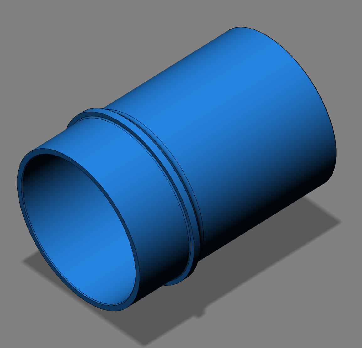
I have researched and got quotes from lminer manufacturing companies in the past, but I recently visited a local cylinder liner company, and was so impressed by their quality, friendliness and pricing, I have decided to have some new liners made for Brian’s engine, and in doing so, test the feasibility of making new ones for future piston batches, and the big bore engine.
I wasn’t planning to do this so soon, but the big bore engine is gathering momentum a little quicker than anticipated, as I have now found a possible forging that is close on 96mm or 1086 cubic centimetres, plus I am simplifying the whole process to make it more cost effective. I am now looking at more expensive pistons, to save on cylinder reworking, and as a bonus it retains the original look of things., and reduces the modification count.
My base philosophy is to make new parts rather than destroy old stock, but in the cylinders case, it’s a little too big of a step to make new ones of these…yet!
As a result, I have updated the 3D CAD version of the OEM model I did years ago, to fit the new Omega pistons, and sent a 2d & 3D file to the liner company to push this along. I don’t have any orders yet, but these liners will be around £100 each, and be sized & honed to swap into the existing cylinders without any further machining. If anybody else would like bespoke one off liners drop me a line, and I’ll draw them up and arrange manufacture.
The first batch of four will be ready by the end of April according to the company, but the usual lead time is 4-6 weeks, so I grateful they have arranged to speed up the process, and they will be placed in Brian’s engine and hopefully powering us to the 2013 Dutch International.
Panhard Ignition Trigger Testing (video) 3
07/04/13 10:13 Filed in: Panhard Ignition
Just quick update, some video 480p clips, showing the crank speed sequential spark tests with an oversized air gap, and a quick snippet of sequential sparking at fast idle speed. The Top & bottom plugs are cylinder 1, and the middle two are cylinder 2, just in case you are wondering which is which., easy if you look at the first video really.
Panhard Twin Plugging & Ignition Options 2
07/04/13 02:26 Filed in: Panhard Ignition
So now I have sequential ignition, using the Imfsoft IgnitionTCI 6.1, an Audi ignition module, and single fire coils for a twin spark set up on the Panhard, but it is all moving upwards in price. The Imfsoft ignition is reasonably cost effective for its capabilities, switchable dual advance curves, two crank or camshaft sensor inputs, and two additional (analogue or digital) inputs that can modify the running advance curve. The Audi 4 x Inputs, 4 x outputs is needed to increase the outputs of the IgnitionTCI 6.1 without overloading the 15A limit for each output.
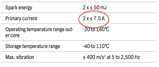
In an ideal world, it would be nice to use modern stick coils or pencil coils, but that’ll be for another day, because after trolling through the Bosch ignition catalogues, there is it seems a specially developed coil for twin spark engines.

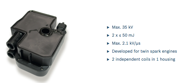
All I needed was a price and here is the Bosch info.
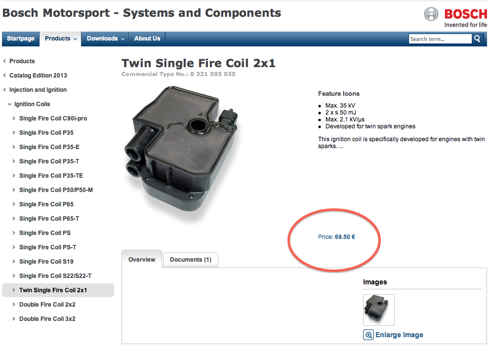
A quick phone call to a local motor factors and it ends up being £93 each!
I don’t come from a garage or vehicle maintenance background, so I didn’t recognise this coil type at first, and I was trying to work out whose engine it was used in. Alfa Romeo do a twin spark, but it has a top hat coil and a pigtail HT lead for the second plug. Honda do a twin plug engine, which uses a SAAB like strip of interconnected stick coils, but then its probably a Denso component. A further search on the internet, soon told me it was a Mercedes Benz application, so now there was more leads.
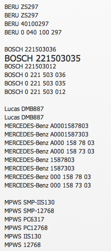
More searching on the internet and these cross references come up, so by trolling some more I can reduce it down to £50 each for a new Mapco version, so the cost is coming down. I already have the Audi ignition module from my motorcycle ignition work, plus some other four channel ignition drivers, but maybe this coils inputs could be paired (combining 1a & 1b), and possibly need an additional ignition control module?
Further digging revealed it could, remember the limit is 15A, so another good result.
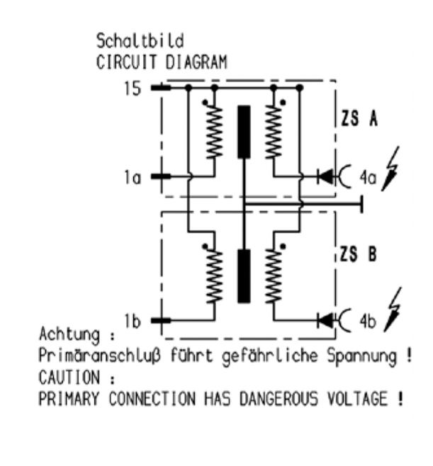
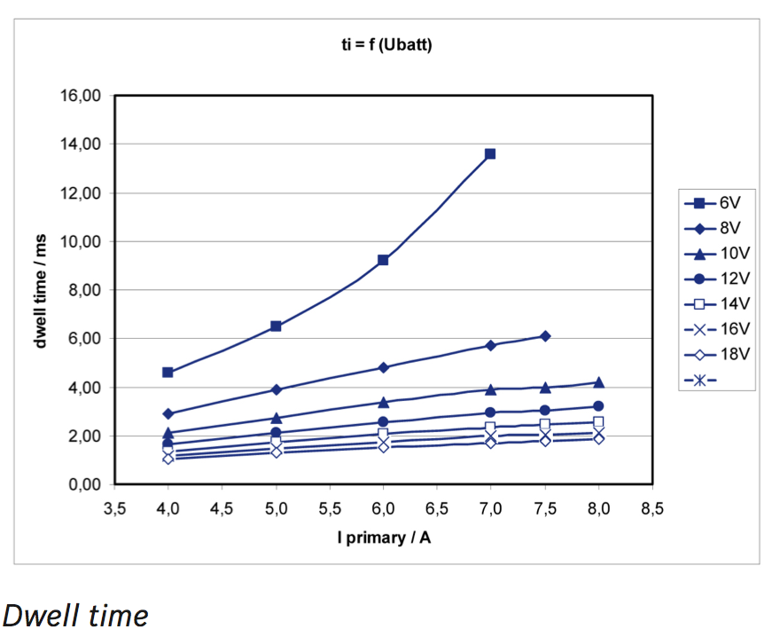
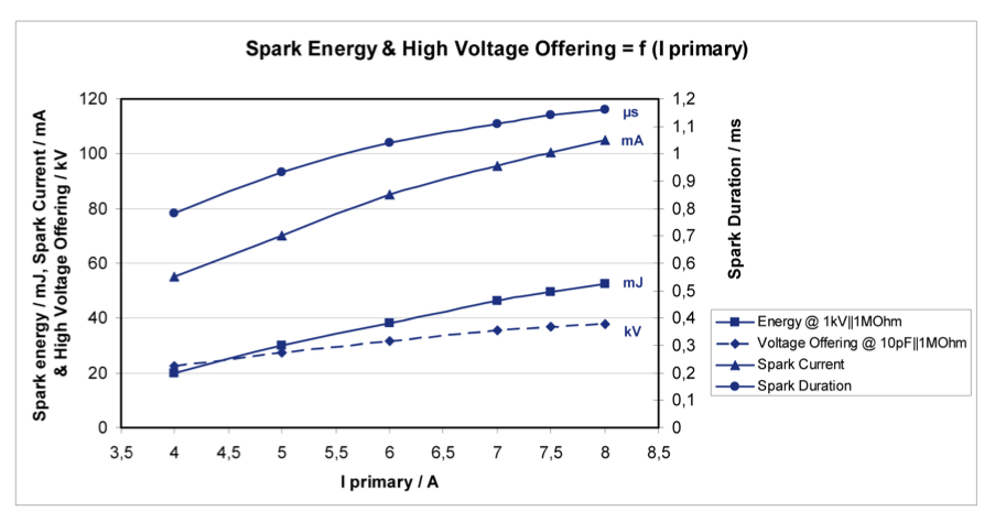
A further look at the dwell chart shows that it is possible to use the 15A limit of the 1A & 1B outputs of the Ignition TCI 6.1, as long as you limit the dwell time, and here’s the confirmation. Dwell and spark energy graphs below.
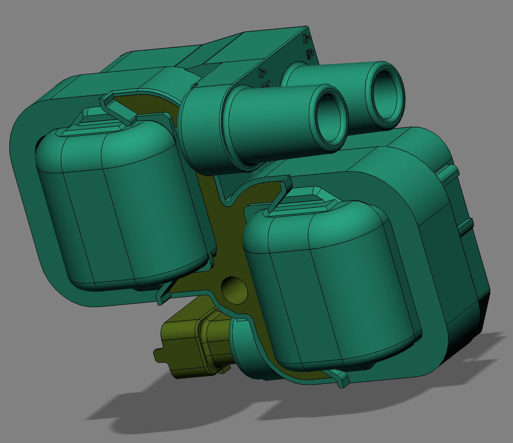
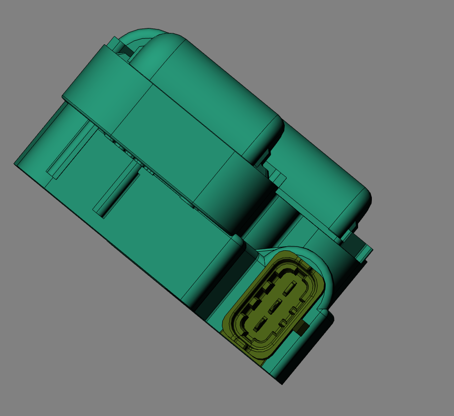
If you want a picture of the unit, here it is in CAD. The connector is a 3 way Bosch Kompakt or Compact type, and it uses Junior Timer or FASTON internals.
Hopefully the parcel in the post will drop in the door and I can test these units, and double check the current draw and spark quality. Thanks to Jean Paul Cesar for his collaboration on this project, because without it, I would have taken a wrong turn, especially trying to use the 2x2 coil pack, and taken longer to complete, when time is getting short to finish the engine for the 2013 International.
In an ideal world, it would be nice to use modern stick coils or pencil coils, but that’ll be for another day, because after trolling through the Bosch ignition catalogues, there is it seems a specially developed coil for twin spark engines.
All I needed was a price and here is the Bosch info.
A quick phone call to a local motor factors and it ends up being £93 each!
I don’t come from a garage or vehicle maintenance background, so I didn’t recognise this coil type at first, and I was trying to work out whose engine it was used in. Alfa Romeo do a twin spark, but it has a top hat coil and a pigtail HT lead for the second plug. Honda do a twin plug engine, which uses a SAAB like strip of interconnected stick coils, but then its probably a Denso component. A further search on the internet, soon told me it was a Mercedes Benz application, so now there was more leads.
More searching on the internet and these cross references come up, so by trolling some more I can reduce it down to £50 each for a new Mapco version, so the cost is coming down. I already have the Audi ignition module from my motorcycle ignition work, plus some other four channel ignition drivers, but maybe this coils inputs could be paired (combining 1a & 1b), and possibly need an additional ignition control module?
Further digging revealed it could, remember the limit is 15A, so another good result.
A further look at the dwell chart shows that it is possible to use the 15A limit of the 1A & 1B outputs of the Ignition TCI 6.1, as long as you limit the dwell time, and here’s the confirmation. Dwell and spark energy graphs below.
If you want a picture of the unit, here it is in CAD. The connector is a 3 way Bosch Kompakt or Compact type, and it uses Junior Timer or FASTON internals.
Hopefully the parcel in the post will drop in the door and I can test these units, and double check the current draw and spark quality. Thanks to Jean Paul Cesar for his collaboration on this project, because without it, I would have taken a wrong turn, especially trying to use the 2x2 coil pack, and taken longer to complete, when time is getting short to finish the engine for the 2013 International.
Panhard Twin Plugging & Ignition Options 1
06/04/13 11:35 Filed in: Panhard Ignition
It is one thing to twin plug a cylinder, it is a totally different thing to get the right quality sparks. There are two options, wasted or sequential twin plugging. I mistakenly thought I could achieve sequential twin plug sparking with double ended coils, when really it would have only been wasted, but it took a French friend to put me straight, thank you Jean Paul.
Originally, I was going to use stick coils, or pencil coils, but the Panhard heads and torsion bar castings do not lend themselves to a satisfactory fixing solution, plus time is running out, and the added complication of angling the spark plugs, using 10mm plugs and a bespoke adaptor seems like a lot of trouble for little gain.
Historically, Hampe did a wasted system over fifty years ago, using four standard coils, two times two wired in parallel, with an additional contact breaker placed inside the distributor, and an added cam to trigger this second set of points. Nowadays this wouldn’t be required, as you could use the OEM sequential points trigger and a modern ignition control module to switch on the additional coils, but this is digressing slightly.
What are the issues with twin plugging? Well it is nicely summed up here, in this article taken from the Vincent Owners Club if I remember correctly.
Now to sparks. Both Roger Haylett and Gordon Colquhoun want to know about double-ended coils and twin sparks - both having had problems. When fitting twin plugs into a head the concept of using a double-ended coil, fitted into the standard ignition system, may seem ideal, but it doesn't work out. Why? Well, examine where the double-ended coils come from. They are invariably from so-called idle-spark systems, where one cylinder is fired on its compression stroke, and the other end is feeding another cylinder, which will be on its induction stroke (though exactly where depends on whether it is a parallel twin, four, or vee-twin). What you need to know is that the voltage required to make a spark depends on the pressure of the gas it is trying to spark through. So, in an idle spark system, the voltage required is only slightly more than in a single-ended one, because one cylinder is under compression (say 150 psi), but the other isn't (ie, less than 15 psi). So almost all of the voltage appears on the firing cylinder, and a very weak, low voltage spark, occurs in the other one (usually not enough energy even to fire a mixture, which is why it works on vee-twins, which can be well on to the induction stroke, and filling with mixture). Try the same coil on a twin plug head and you need twice the voltage, which is way above the design criteria. So it may not fire reliably.
There are a variety of fixes. Best of the lot is to use a pair of coils in series, to drive the two plugs - preferably a pair of identical-type coils, but they don't need to be better matched than that. Of course, this requires half voltage coils- ok if you can find a pair of six volt ones to run on 12 volt (you might look at 12 volt ones with ballast resistors, and bypass the resistors which makes them six-eight volt types). A number of people have told me that, like Gordon, they have run coils in parallel, but theoretically, it isn't a good idea. Coils in parallel need to balance and so too does the sparking voltage of the plugs. If they don't go off together, then the single spark immediately loads one coil, which may suck power from the primary of the other, and the second spark may not occur. So it probably works better than the original double-ended coil, which misfires completely, but you may actually be running single spark some, or all, of the time, and not, necessarily, firing the same plug every time. Optimising the timing may be impossible, if single and twin optima are different, although the engine will not, necessarily, show ignition problems. However, if it works for you, I'm not going to say it doesn't - but I recommend the series arrangement.
If you are trying to do a Twin, then series or parallel, it makes for a lot of coils. Here, though, there is a further, attractive and sound, alternative, although it may mean altering your 'distributor', be it single-bump cam and one pair of points, or twin-bump cam and a single set of points. Instead, what you need is both the twin-bump cam and the twin points. Now fit a double-ended coil to each set of points, and wire each in conventional double-ended fashion, ie, one end to a plug on one cylinder and the other end to a plug on the other cylinder. Now you are not asking too much of either coil, but you will get twin sparks on each cylinder reliably. The idea extends to fours and sixes too, if you can find the appropriate multi-lobe cam and multi-points assembly - and work out exactly the right places to send the extra leads.
How am I going to do Brian’s engine?,
Well it looks like this
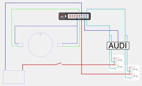
I n the above, I am using an Audi ignition control module, which has four inputs & outputs to trigger the GND signals from the programmable ignition module, which in turn feed two single fire coils per cylinder. This now gives a sequential ignition sequence to the firing order, and it should mean there is a good quality spark at all times. The last thing is I cannot use the standard coils I show in the schematic, as the Imfsoft ignition says “standard coils are not supported”, so I have to use modern single fire coils instead.
Incidentally you could do a wasted spark version, using two magnets, one sensor, and using a pair of say double fire coils (2CV, double ended motorcycle types) with one coil feeding the top plugs & the other the bottom plugs. This is essentially what Hampe did, but they were limited by using standard coils & a need to make a failsafe system, that could run of one set of points.
I have managed to get sequential twin spark working in theory using double fire motorcycle coils, but these won’t work because the coil voltage for the spark will be biased towards the cylinder under compression, but hopefully in the next few days a new set of compact twin single fire coils will arrive in the post, so I will find out whether the current draw is too much for the Imfsoft IgnitionTCI 6.1.
To be updated...
Originally, I was going to use stick coils, or pencil coils, but the Panhard heads and torsion bar castings do not lend themselves to a satisfactory fixing solution, plus time is running out, and the added complication of angling the spark plugs, using 10mm plugs and a bespoke adaptor seems like a lot of trouble for little gain.
Historically, Hampe did a wasted system over fifty years ago, using four standard coils, two times two wired in parallel, with an additional contact breaker placed inside the distributor, and an added cam to trigger this second set of points. Nowadays this wouldn’t be required, as you could use the OEM sequential points trigger and a modern ignition control module to switch on the additional coils, but this is digressing slightly.
What are the issues with twin plugging? Well it is nicely summed up here, in this article taken from the Vincent Owners Club if I remember correctly.
Now to sparks. Both Roger Haylett and Gordon Colquhoun want to know about double-ended coils and twin sparks - both having had problems. When fitting twin plugs into a head the concept of using a double-ended coil, fitted into the standard ignition system, may seem ideal, but it doesn't work out. Why? Well, examine where the double-ended coils come from. They are invariably from so-called idle-spark systems, where one cylinder is fired on its compression stroke, and the other end is feeding another cylinder, which will be on its induction stroke (though exactly where depends on whether it is a parallel twin, four, or vee-twin). What you need to know is that the voltage required to make a spark depends on the pressure of the gas it is trying to spark through. So, in an idle spark system, the voltage required is only slightly more than in a single-ended one, because one cylinder is under compression (say 150 psi), but the other isn't (ie, less than 15 psi). So almost all of the voltage appears on the firing cylinder, and a very weak, low voltage spark, occurs in the other one (usually not enough energy even to fire a mixture, which is why it works on vee-twins, which can be well on to the induction stroke, and filling with mixture). Try the same coil on a twin plug head and you need twice the voltage, which is way above the design criteria. So it may not fire reliably.
There are a variety of fixes. Best of the lot is to use a pair of coils in series, to drive the two plugs - preferably a pair of identical-type coils, but they don't need to be better matched than that. Of course, this requires half voltage coils- ok if you can find a pair of six volt ones to run on 12 volt (you might look at 12 volt ones with ballast resistors, and bypass the resistors which makes them six-eight volt types). A number of people have told me that, like Gordon, they have run coils in parallel, but theoretically, it isn't a good idea. Coils in parallel need to balance and so too does the sparking voltage of the plugs. If they don't go off together, then the single spark immediately loads one coil, which may suck power from the primary of the other, and the second spark may not occur. So it probably works better than the original double-ended coil, which misfires completely, but you may actually be running single spark some, or all, of the time, and not, necessarily, firing the same plug every time. Optimising the timing may be impossible, if single and twin optima are different, although the engine will not, necessarily, show ignition problems. However, if it works for you, I'm not going to say it doesn't - but I recommend the series arrangement.
If you are trying to do a Twin, then series or parallel, it makes for a lot of coils. Here, though, there is a further, attractive and sound, alternative, although it may mean altering your 'distributor', be it single-bump cam and one pair of points, or twin-bump cam and a single set of points. Instead, what you need is both the twin-bump cam and the twin points. Now fit a double-ended coil to each set of points, and wire each in conventional double-ended fashion, ie, one end to a plug on one cylinder and the other end to a plug on the other cylinder. Now you are not asking too much of either coil, but you will get twin sparks on each cylinder reliably. The idea extends to fours and sixes too, if you can find the appropriate multi-lobe cam and multi-points assembly - and work out exactly the right places to send the extra leads.
How am I going to do Brian’s engine?,
Well it looks like this
I n the above, I am using an Audi ignition control module, which has four inputs & outputs to trigger the GND signals from the programmable ignition module, which in turn feed two single fire coils per cylinder. This now gives a sequential ignition sequence to the firing order, and it should mean there is a good quality spark at all times. The last thing is I cannot use the standard coils I show in the schematic, as the Imfsoft ignition says “standard coils are not supported”, so I have to use modern single fire coils instead.
Incidentally you could do a wasted spark version, using two magnets, one sensor, and using a pair of say double fire coils (2CV, double ended motorcycle types) with one coil feeding the top plugs & the other the bottom plugs. This is essentially what Hampe did, but they were limited by using standard coils & a need to make a failsafe system, that could run of one set of points.
I have managed to get sequential twin spark working in theory using double fire motorcycle coils, but these won’t work because the coil voltage for the spark will be biased towards the cylinder under compression, but hopefully in the next few days a new set of compact twin single fire coils will arrive in the post, so I will find out whether the current draw is too much for the Imfsoft IgnitionTCI 6.1.
To be updated...
Panhard Front Timing Cover Modifications 3
03/04/13 22:27 Filed in: Panhard Engine | Panhard Ignition
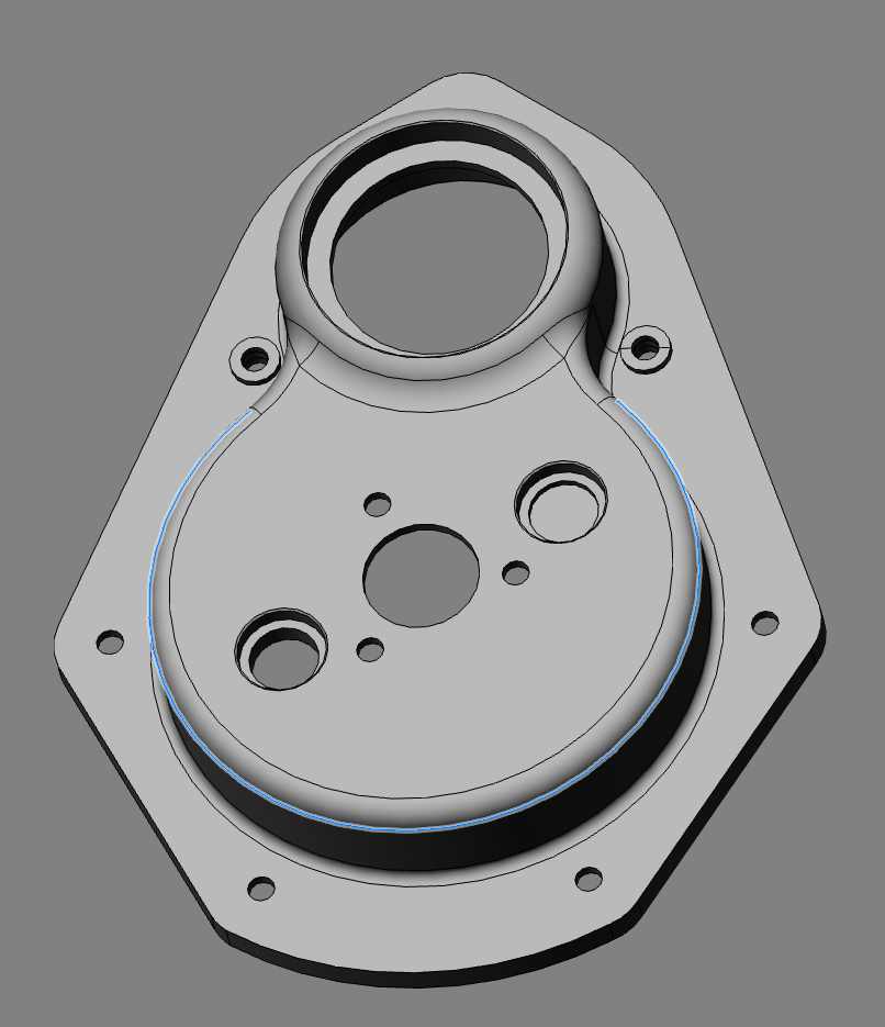
I instructed the 3D modeller to go ahead and make four of these front covers, I have orders for two, and I have decided to make two to suit the Peugeot sensors and make two more plain variants, without sensor locations. I will rework these to suit later, as it gives me a platform to try other sensor options later.
The new covers will both have single sensor locations, with the ability to machine out the other location, which does not have a through hole, so it is essentially an integrated blanking plug. I need this other sensor location for twin plugging when using the Ignition TCI6.1 from Imfsoft, but if I revert to a toothed wheel configuration, the single sensor will be enough to satisfy the plentiful options that exist for standalone programmable engine management systems.
Single sensor version with Peugeot 405/406 crankshaft sensor, and below this, the twin sensor version.
I shall order a few 45x68x10 Viton R23 seals for the front pulley aperture in the next few days, and possibly book these in at the anodisers for a coating of OEM black, when they are completed.
Panhard Ignition Imfsoft Software 1
03/04/13 22:02 Filed in: Panhard Ignition
A little update on my observations so far on using the Imfsoft software that comes with the IgnitionTCI 6.1
I have noticed I can get a buffer error, and the program locks out, and as a result I have to close Windows XP and restart. I’ll get in touch with the folks at Imfsoft and see if it’s a MAc emulation thing or Windows related.
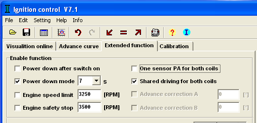
I have been reading and writing files to the unit, and I noticed that I managed to alter the ignition settings by checking the these boxes. It’s covered in the manual what they mean, but in my case they were unchecked and I stumbled upon the right behaviour.
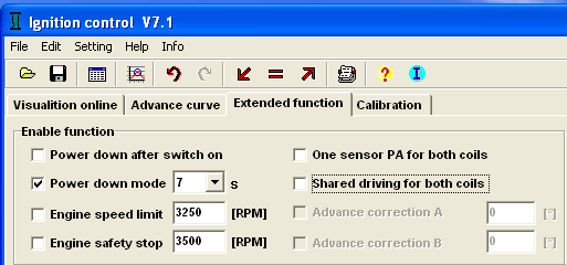
This gives sequential spark from two sensors, and two coils. This is what is required for sequential twin plugging on a Panhard twin.
This gives shared sparks on both coil outputs, and a spark every time it passes a sensor, so in a sense it’s converts the above sequential into wasted spark for twin plugged heads, or wasted spark from two sensors.
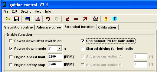
This is the typical wasted spark set up for a twin, if you are using a twin ended coil, but the coil and sensor have to be in the PA inputs and outputs. You would use this setting for a standard single plug cylinders on a Panhard with a twin ended coil.
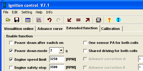
Another thing, if you check the Engine safety stop box, the sparks stop at this threshold and if you slow down, they DO NOT restart, so this is a KILL switch upper limit. I assume that when the engine stops, you can restart as per normal. The Engine speed limit IS the rev limiter, and it does work OK, when you slow the rig down , the spark is restored.
I have noticed I can get a buffer error, and the program locks out, and as a result I have to close Windows XP and restart. I’ll get in touch with the folks at Imfsoft and see if it’s a MAc emulation thing or Windows related.
I have been reading and writing files to the unit, and I noticed that I managed to alter the ignition settings by checking the these boxes. It’s covered in the manual what they mean, but in my case they were unchecked and I stumbled upon the right behaviour.
This gives sequential spark from two sensors, and two coils. This is what is required for sequential twin plugging on a Panhard twin.
This gives shared sparks on both coil outputs, and a spark every time it passes a sensor, so in a sense it’s converts the above sequential into wasted spark for twin plugged heads, or wasted spark from two sensors.
This is the typical wasted spark set up for a twin, if you are using a twin ended coil, but the coil and sensor have to be in the PA inputs and outputs. You would use this setting for a standard single plug cylinders on a Panhard with a twin ended coil.
Another thing, if you check the Engine safety stop box, the sparks stop at this threshold and if you slow down, they DO NOT restart, so this is a KILL switch upper limit. I assume that when the engine stops, you can restart as per normal. The Engine speed limit IS the rev limiter, and it does work OK, when you slow the rig down , the spark is restored.
Panhard Ignition Trigger Testing 2
03/04/13 18:17 Filed in: Panhard Ignition
I had a request from a fellow Panhardista to look at the ignition units performance at 8V dc, so after work today I started to have a play, and I hooked up a zener diode, and a resistor to pull the 12V battery down to 6V.
I connected up this 6V to the IgnitionTCI 6.1 and used a cordless drill to rotate the trigger wheel on the rig, and it performed exactly as yesterday!
This is too good, so I thought I’d drop the voltage some more, so I added a LED, and pulled it down to just over 4V, whilst the screen video was running (edited out), which to be fair is 1V over the rated minimum for the ignition, and yet again the programmable ignition performed admirably. Good result.
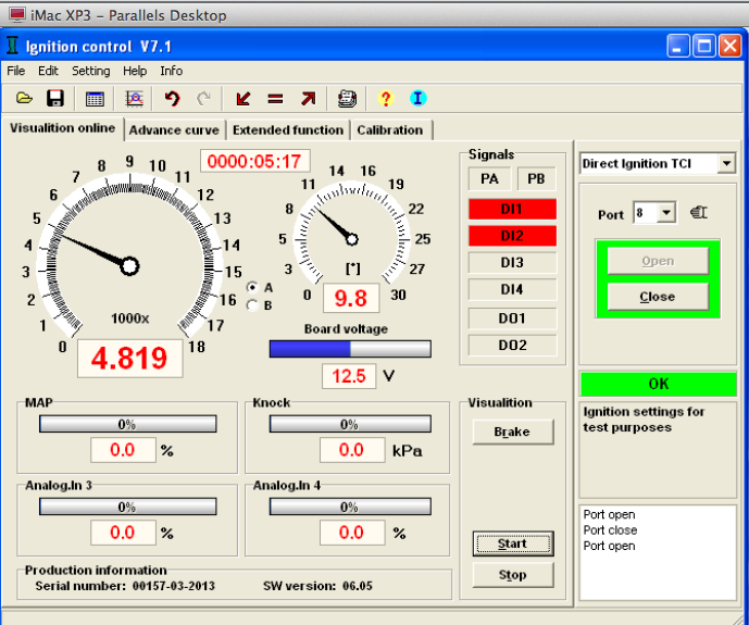
Here’s a video clip, a little bit too long, but you get some idea. I used the drill slowly at first, then held it steady (around 65 rpm), and then went a little faster. The smaller dial is the advance curve, and it is jumping up to reach it’s lowest value. The lowest speed it can calculate advance is 180 rpm, so most of time it is below this.
Afterwards, I added a second sensor, but used the first sensors wiring that fed the Imfsoft ignition unit, to check the sensor. i also increased the air gap to 4mm from 2.5mm, to see how this would affect slow speed cranking performance, and there was no change.
I then wired up the first sensor again, so I had two sensors 180º apart at the cam, therefore 360º apart at the crankshaft, and checked I was getting sequential ignition, AND I was.
Better still I was able to flick start a spark, by rotating the wheel magnet past the sensor. This is a bit like using a starting handle, which is even more impressive.
I am still using the inductive sensors from a Peugeot 405/406, and to be honest I am not thinking of changing this set up. I know a Hall effect sensor has greater tolerance to interference, but these sensors do have a separate ground pin, and they work well enough for me. Plus the air gap was at 4mm by the time I had finished testing, so that gives plenty of tolerance to concerns about the magnetic tips collecting ferrous particles.
The only thing I am likely to change is the size & quality of the magnet, because the new one will be a smaller diameter & made of SmCo26, a high temperature samarium cobalt variant.
I connected up this 6V to the IgnitionTCI 6.1 and used a cordless drill to rotate the trigger wheel on the rig, and it performed exactly as yesterday!
This is too good, so I thought I’d drop the voltage some more, so I added a LED, and pulled it down to just over 4V, whilst the screen video was running (edited out), which to be fair is 1V over the rated minimum for the ignition, and yet again the programmable ignition performed admirably. Good result.
Here’s a video clip, a little bit too long, but you get some idea. I used the drill slowly at first, then held it steady (around 65 rpm), and then went a little faster. The smaller dial is the advance curve, and it is jumping up to reach it’s lowest value. The lowest speed it can calculate advance is 180 rpm, so most of time it is below this.
Afterwards, I added a second sensor, but used the first sensors wiring that fed the Imfsoft ignition unit, to check the sensor. i also increased the air gap to 4mm from 2.5mm, to see how this would affect slow speed cranking performance, and there was no change.
I then wired up the first sensor again, so I had two sensors 180º apart at the cam, therefore 360º apart at the crankshaft, and checked I was getting sequential ignition, AND I was.
Better still I was able to flick start a spark, by rotating the wheel magnet past the sensor. This is a bit like using a starting handle, which is even more impressive.
I am still using the inductive sensors from a Peugeot 405/406, and to be honest I am not thinking of changing this set up. I know a Hall effect sensor has greater tolerance to interference, but these sensors do have a separate ground pin, and they work well enough for me. Plus the air gap was at 4mm by the time I had finished testing, so that gives plenty of tolerance to concerns about the magnetic tips collecting ferrous particles.
The only thing I am likely to change is the size & quality of the magnet, because the new one will be a smaller diameter & made of SmCo26, a high temperature samarium cobalt variant.
Panhard Ignition Trigger Testing 1
01/04/13 11:03 Filed in: Panhard Ignition
Easter Monday Bank Holiday, and April 1st too, interesting mix, almost escaped the usual pranks, 55 minutes to go!
I thought I’d do something less taxing today, and tinker with the ignition and double check the Peugeot sensors work OK.
I have the Imfsoft ignition unit, and the software up and running on the desktop, so I just need to make a test loom, so I can try different ignition wheels. I also have a MicroSquirt v2 & v3, so over the next few weeks, when I am waiting for parts, I will play with these too.
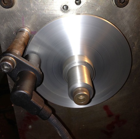
Here’s the rig, the old trusty washing machine motor & variable speed drive, complete with Peugeot sensor and simple magnetic trigger. I’ll be using a smaller Samarium Cobalt magnet in Brian’s engine (SmCo26 to be precise) which is safe up to 250-300ºC, which is more than enough!
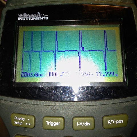
Here’s a typical low grade pocket oscilloscope trace, with the disc turning at around 600 rpm.
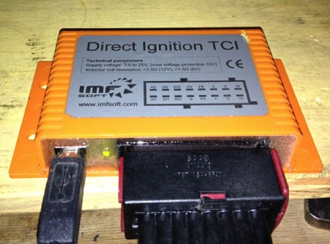
Very clean & strong spikes, which should mean good recognition at the ignition unit, and sure enough it does…with the wheel spinning at 677 t/min (the slowest my motor will go), the Imfsoft Ignition TCI glows green...
…and the display starts to register the RPMs.
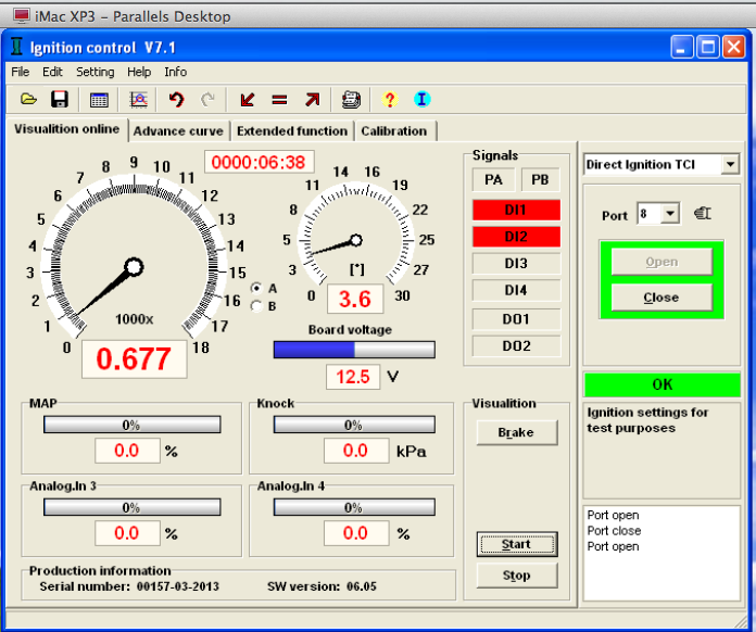
As the revs rise, obviously things get better. I went above my anticipated speeds, to check there was no over voltage faults, but the reading was steady in the software window.
This screen grab is actually displaying camshaft speed, which is half the actual engine revs of 9638 t/min.
The ultimate test is how slow can the engine turn and still be recognised by the ignition controller. I have had the MicroSquirt B&G code trigger at 50 rpm, and the MSExtra code trigger at 24 rpm, but I was surprised to see the Imfsoft unit go this low as well. Here’s a screen grab in a movie format, this time using a cordless drill to rotate the trigger wheel.
I thought I’d do something less taxing today, and tinker with the ignition and double check the Peugeot sensors work OK.
I have the Imfsoft ignition unit, and the software up and running on the desktop, so I just need to make a test loom, so I can try different ignition wheels. I also have a MicroSquirt v2 & v3, so over the next few weeks, when I am waiting for parts, I will play with these too.
Here’s the rig, the old trusty washing machine motor & variable speed drive, complete with Peugeot sensor and simple magnetic trigger. I’ll be using a smaller Samarium Cobalt magnet in Brian’s engine (SmCo26 to be precise) which is safe up to 250-300ºC, which is more than enough!
Here’s a typical low grade pocket oscilloscope trace, with the disc turning at around 600 rpm.
Very clean & strong spikes, which should mean good recognition at the ignition unit, and sure enough it does…with the wheel spinning at 677 t/min (the slowest my motor will go), the Imfsoft Ignition TCI glows green...
…and the display starts to register the RPMs.
As the revs rise, obviously things get better. I went above my anticipated speeds, to check there was no over voltage faults, but the reading was steady in the software window.
This screen grab is actually displaying camshaft speed, which is half the actual engine revs of 9638 t/min.
The ultimate test is how slow can the engine turn and still be recognised by the ignition controller. I have had the MicroSquirt B&G code trigger at 50 rpm, and the MSExtra code trigger at 24 rpm, but I was surprised to see the Imfsoft unit go this low as well. Here’s a screen grab in a movie format, this time using a cordless drill to rotate the trigger wheel.
Panhard Exhaust Valve Insert & Guide Replacement
31/03/13 20:02 Filed in: Panhard Engine
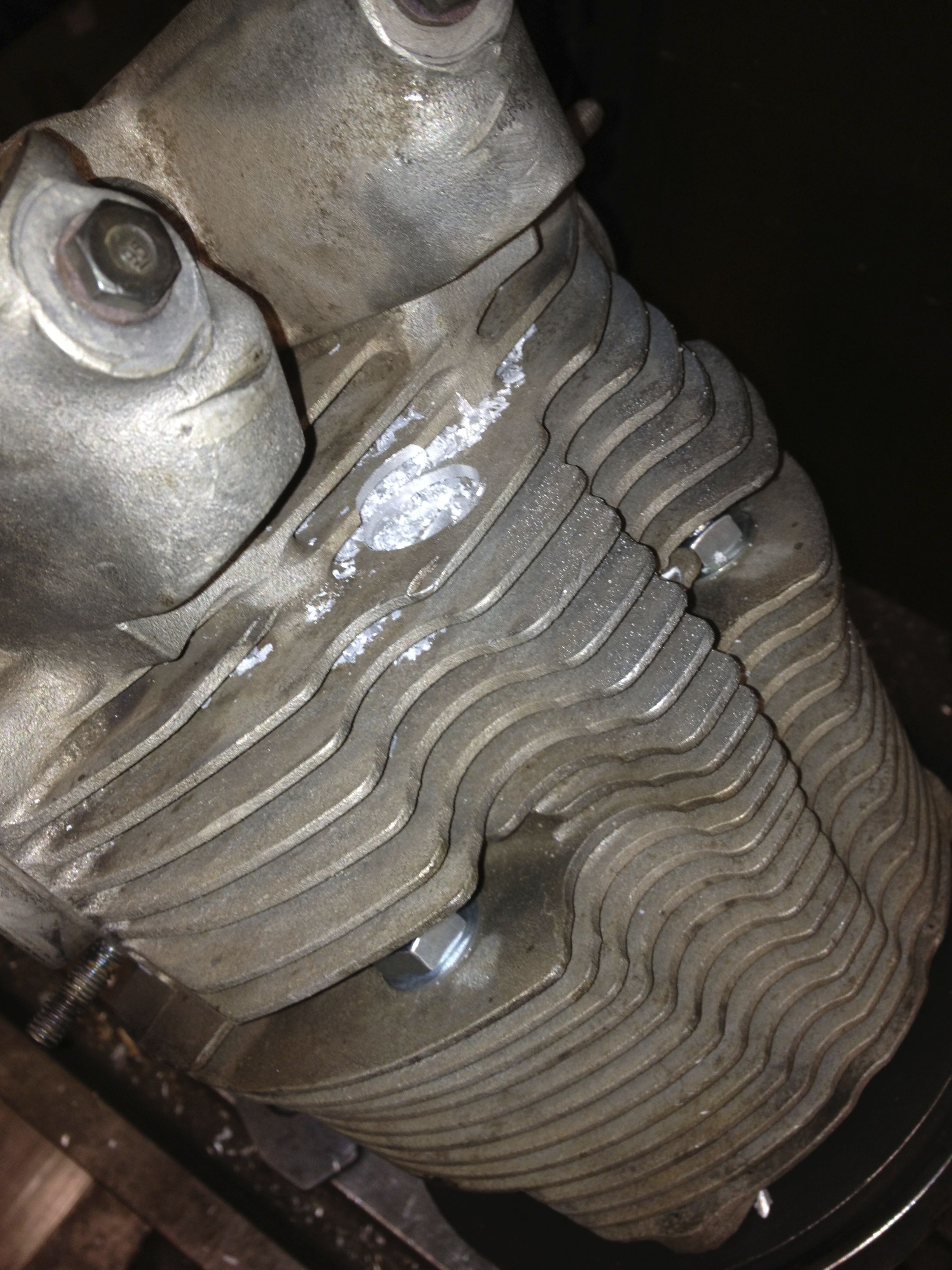
I have to say without doubt, this is the single most awkward task I have tackled on a Panhard engine. Valve guide removal on a 50 year old engine is not for the fainthearted, and even though copious amounts of heat were used, the whole process requires levels of force that make you wince.
After making a suitable drift and warming the cylinder up, (spit just beads off), I inverted it onto my anvil!
After a dozen blows, it started to move, by which time it was cooling, so I decided to drill the inner out some more and lose some of the interference fit. I then heated the cylinder up some more and inverted it quickly on the anvil ( the cotton towelling rag caught alight!), and hit the guide some more. Finally it eased out and the cylinder looked like this.
The seat had been removed previously.
Now the task of refitting the guide, I decide this was first up as the smaller diameter required more heat to open up, so my thinking was do this first, then top up the heat and tackle the insert.I successfully managed this, but it was a two stage process, because even though the guide was -17ºC, it soon warmed when in contact with the cylinder head and it needed a reheat to ease it into the head. I also made a specially turned up brass drift, so as not to damage the new guide.
Anyway, I next did the insert and here it is just installed, blueing on the heat transfer from the cylinder! You can see the new guide too.
All this was possible by modifying my seat installation tool, shown below, complete with burnt paper! This is the interference fit, so you can extract the installation tool, as the seat insert shrinks. It was wonderful to watch as the cold insert heated up from outside to middle as it absorbed the heat, proof that there is a heat transfer path at this point.
Here is the cooler result about half an hour later, so I just need to recut the valve seat, to finish, but that’s for another day.
Definitely not for the faint hearted, and as a result I am going to make some new valve guides next time and re-machine the cylinders each time I do this in the future.
Panhard Twin Plugging Cylinders 2
30/03/13 19:31 Filed in: Panhard Engine
Another day, another dollar, and as Jean Paul Cesar suggested, putting the milling head horizontal was the easiest solution to my limited vertical height, but if the jig had been shorter, it wouldn’t have worked because the locking bar would have fouled the milling table.
Here’s the mill is centred on the OEM spark plug horizontally now. The Elliott Sturdimill is a really flexible piece of kit, and I didn’t realise the mill table could go so high, but to be honest I have never used it like this, and it turned out to be a master stroke, as I didn’t have to modify my jig.
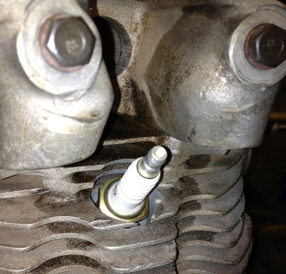
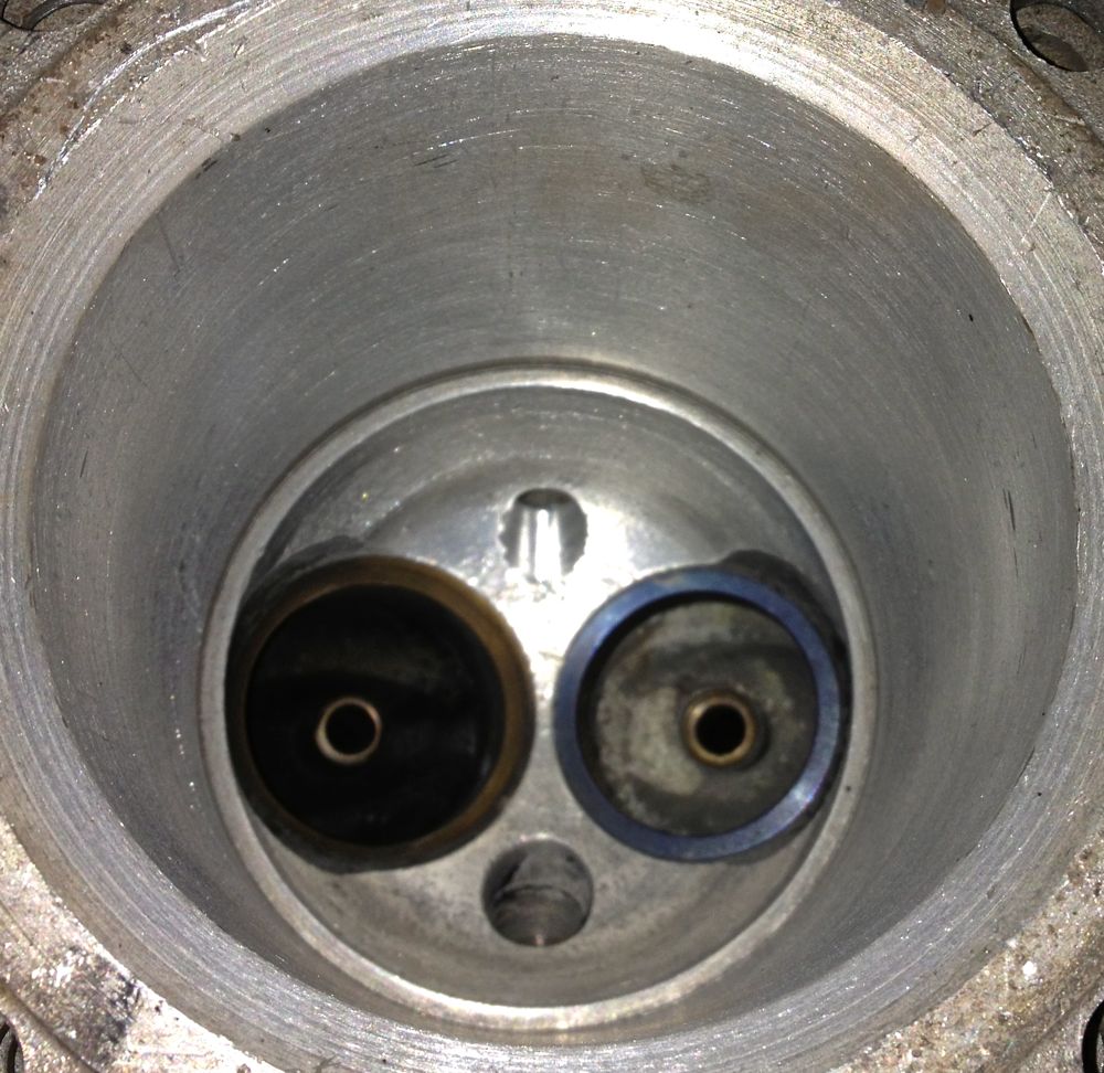
and the chamber side is impressively central too, but just need to rework the exposed threaded area to match the OEM detail
The depth of machining compares well with the OEM plug location.
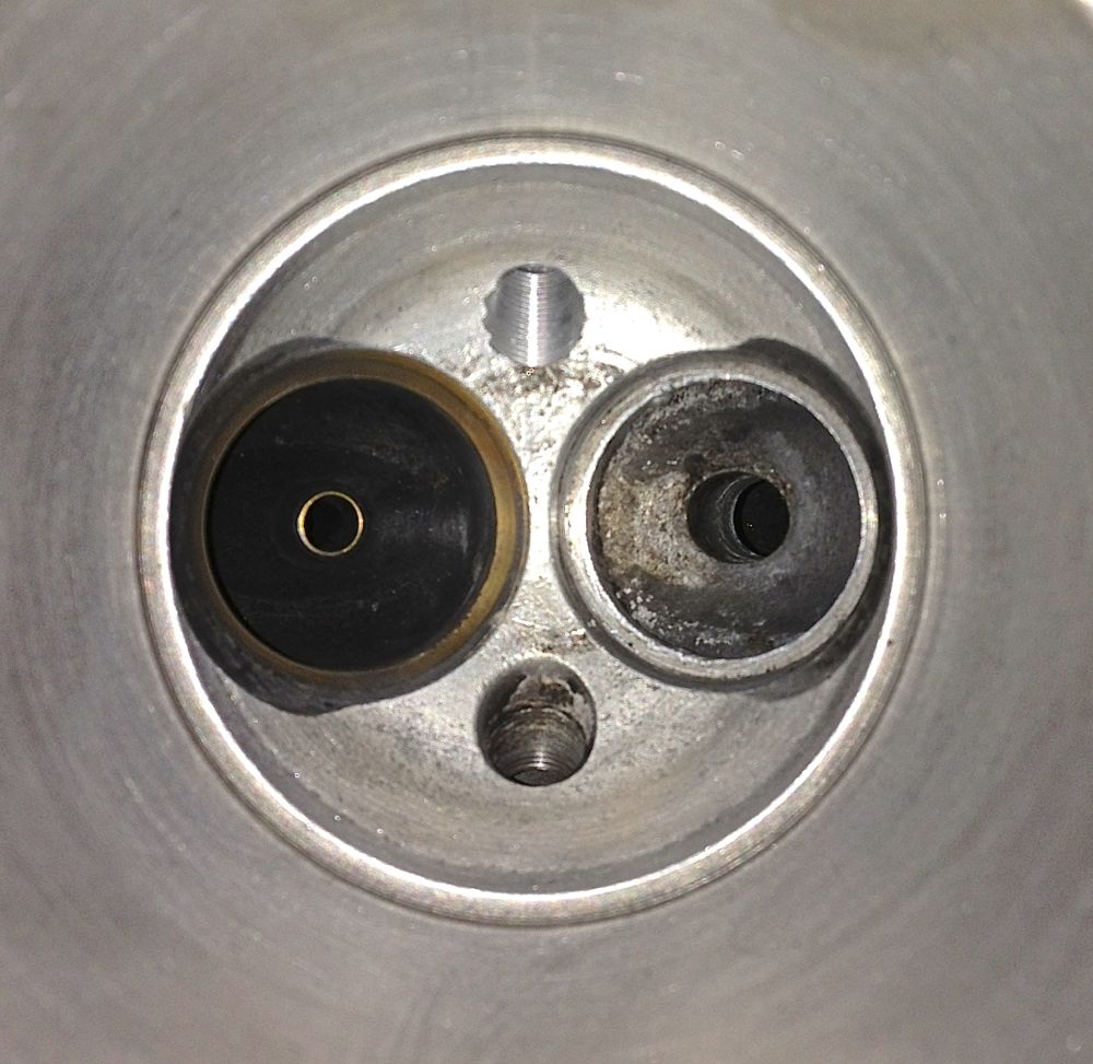
Brian’s other cylinder machined with two plugs in situ, a little more work to clean up the exposed threads and the job is finished.
Here’s the mill is centred on the OEM spark plug horizontally now. The Elliott Sturdimill is a really flexible piece of kit, and I didn’t realise the mill table could go so high, but to be honest I have never used it like this, and it turned out to be a master stroke, as I didn’t have to modify my jig.
and the chamber side is impressively central too, but just need to rework the exposed threaded area to match the OEM detail
The depth of machining compares well with the OEM plug location.
Brian’s other cylinder machined with two plugs in situ, a little more work to clean up the exposed threads and the job is finished.
Panhard Twin Plugging Cylinders 1
29/03/13 21:32 Filed in: Panhard Engine
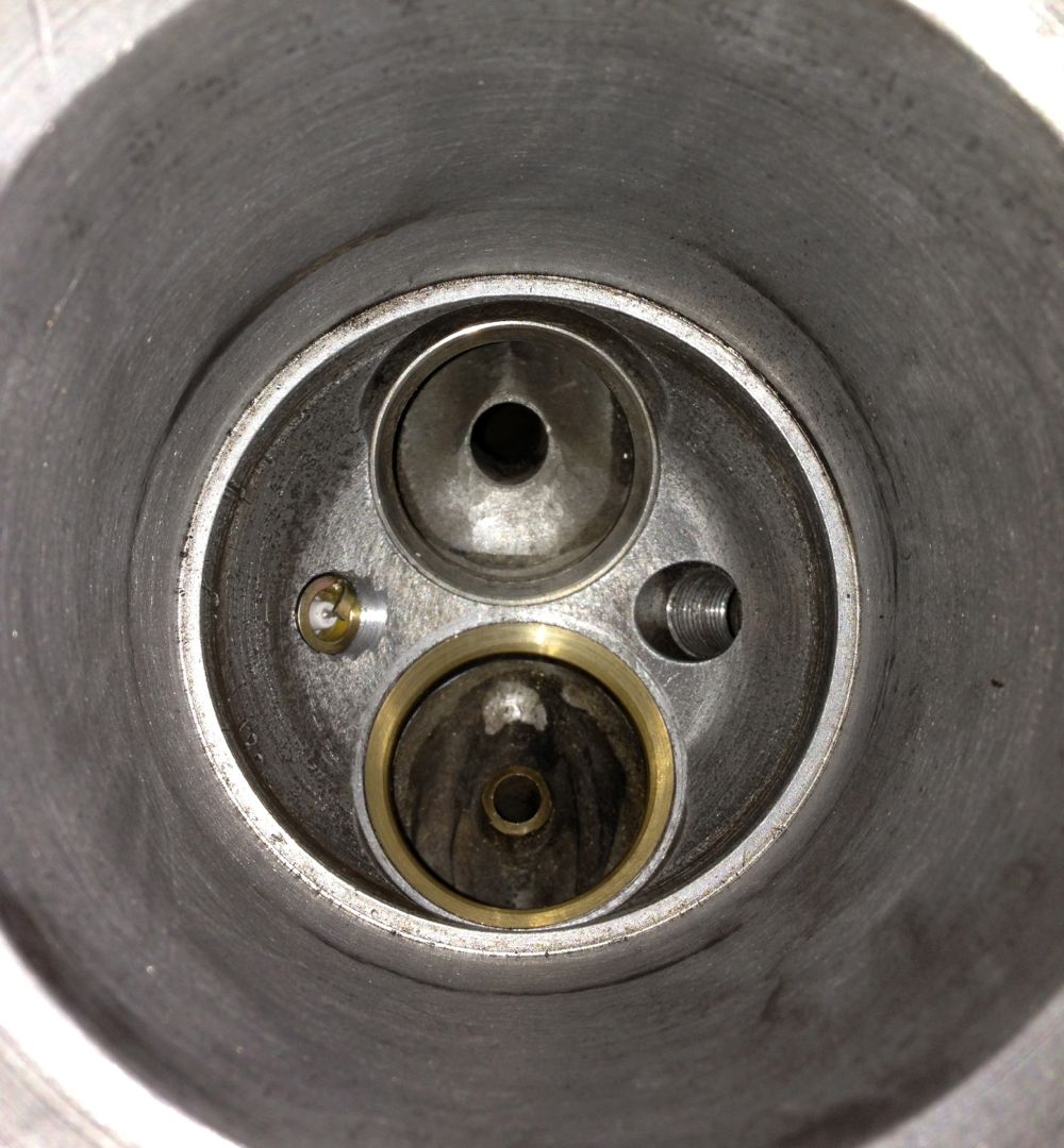
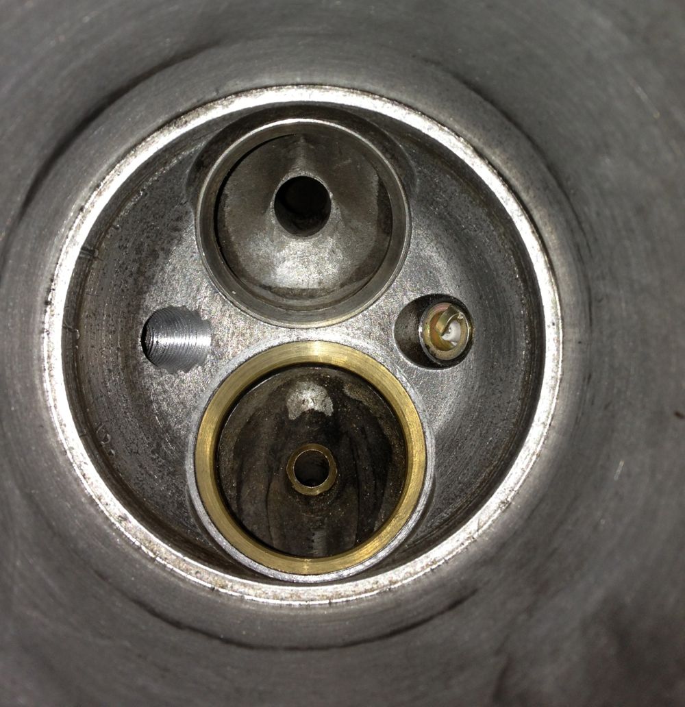
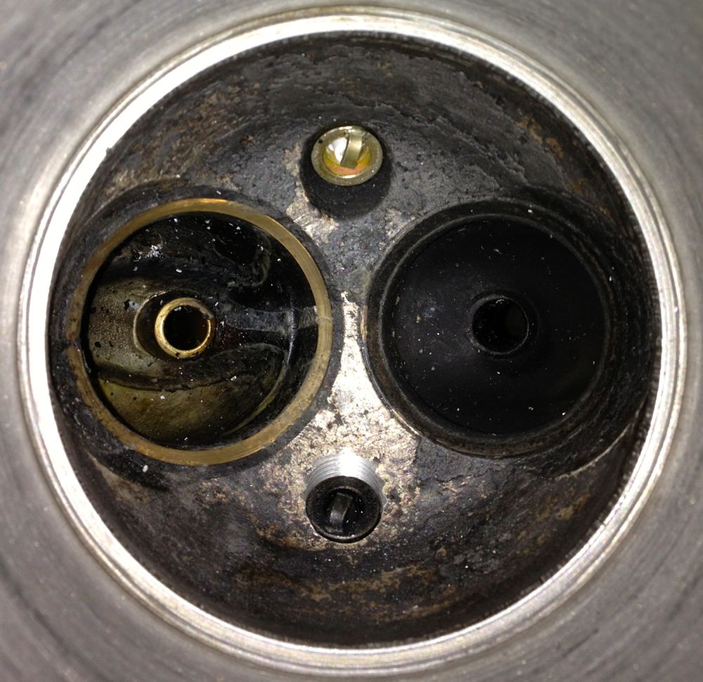
Twin plugging is adding another spark plug to each cylinder, so that each cylinder has two plugs. This is beneficial in a domed piston , domed combustion chamber environment, because the flame front can be chopped short by the lopsided combustion processes. To make sure this non ideal combustion is completed, it’s usual to run plenty of ignition advance, and as the rpm goes up this advance figure rises. High advance exposes the cylinder components to a longer heat exposure, so the engine runs hotter too.
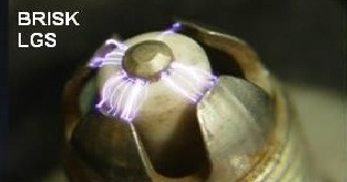
If you look at the Panhard combustion chambers you can see the spark plug angle is less than ideal, and there is evidence of electrode shielding too, so Brian’s engine will have surface
discharge spark plugs, which are at a disadvantage at low speed, & lean mixtures, so fitting an extra spark plug will negate some of this.
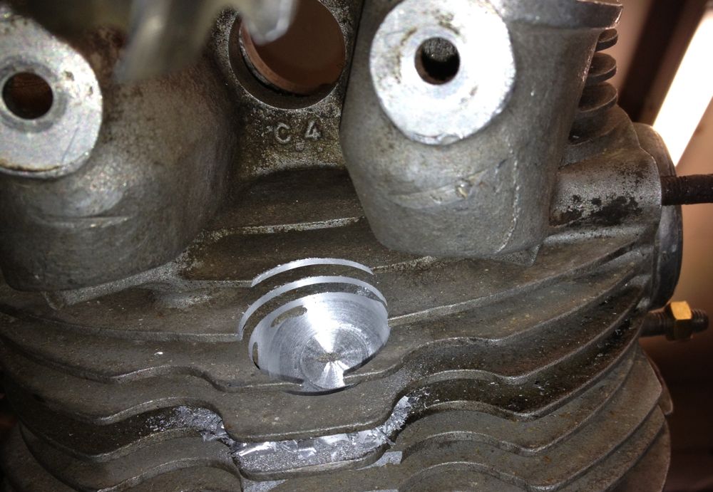
How do you twin plug a cylinder?
You’ll need access to a milling machine ideally, worst case a pillar drill and a Dremel. Sequence of events are,
1. Establish existing spark plug position.
2. rotate cylinder 180º.
3. Drill, tap & mill the spark plug recess.
4. Mill the fins to allow for spanner access.
Here is the start of my jig, which was some reused components from the crankshaft rig, and the honing clamp parts.
Checking everything is vertical and aligned
The cylinder is slid onto a turned down liner, and clamped in situ. Then we locate the centre of the original spark plug.
You have to watch you have enough clearance, and in my case I didn’t have enough height to use the larger milling cutters and associated collets. This mill uses Clarkson screwed shank milling tools, so I needed some long series ones for this kind of work. Unfortunately the first operation is to drill the spark plug hole, actually it isn’t, because i used a 20mm diameter slot drill to remove the fins and create a flat surface for a stock 118º HSS twist drill. When I wound the mill table fully down I couldn’t fit the larger INT 40 collet chuck, so I am looking at shortening the jig, angling the head at 45º, or better still, as fellow Panhardista Jean Paul Cesar suggested ”put the milling head horizontal”.
The latter idea is quite appealing, but that’s assuming the mill table can go high enough, and I’ll have to remove the boring bar from the other end of the mill table. I will know for sure tomorrow, and as I don’t have a surface block to place the jig on and hold it down, I might end up cutting the jig down yet, as I thought previously.
I still managed to do a little bit, here is the cylinder after the 20mm slot drill has cut through the fins, whilst the cylinder awaits the Ø12.5 tapping drill (for the M14 x 1.50 spark plug thread).
If you look at the Panhard combustion chambers you can see the spark plug angle is less than ideal, and there is evidence of electrode shielding too, so Brian’s engine will have surface
discharge spark plugs, which are at a disadvantage at low speed, & lean mixtures, so fitting an extra spark plug will negate some of this.
How do you twin plug a cylinder?
You’ll need access to a milling machine ideally, worst case a pillar drill and a Dremel. Sequence of events are,
1. Establish existing spark plug position.
2. rotate cylinder 180º.
3. Drill, tap & mill the spark plug recess.
4. Mill the fins to allow for spanner access.
Here is the start of my jig, which was some reused components from the crankshaft rig, and the honing clamp parts.
Checking everything is vertical and aligned
The cylinder is slid onto a turned down liner, and clamped in situ. Then we locate the centre of the original spark plug.
You have to watch you have enough clearance, and in my case I didn’t have enough height to use the larger milling cutters and associated collets. This mill uses Clarkson screwed shank milling tools, so I needed some long series ones for this kind of work. Unfortunately the first operation is to drill the spark plug hole, actually it isn’t, because i used a 20mm diameter slot drill to remove the fins and create a flat surface for a stock 118º HSS twist drill. When I wound the mill table fully down I couldn’t fit the larger INT 40 collet chuck, so I am looking at shortening the jig, angling the head at 45º, or better still, as fellow Panhardista Jean Paul Cesar suggested ”put the milling head horizontal”.
The latter idea is quite appealing, but that’s assuming the mill table can go high enough, and I’ll have to remove the boring bar from the other end of the mill table. I will know for sure tomorrow, and as I don’t have a surface block to place the jig on and hold it down, I might end up cutting the jig down yet, as I thought previously.
I still managed to do a little bit, here is the cylinder after the 20mm slot drill has cut through the fins, whilst the cylinder awaits the Ø12.5 tapping drill (for the M14 x 1.50 spark plug thread).
Panhard Front Timing Cover Modifications 2
19/03/13 16:45 Filed in: Panhard Engine
I just got word today the ignition has been despatched from the supplier, so in a few days it should arrive. I have decided to update the 3D model to incorporate the BMW camshaft sensors, so I could explore different possible locations, and this is the result so far. Looks like I might be making a tweak to the cover again, but this would only be if others were interested. The first batch will be as is shown below, as it will delay the item for Brian’s engine too much.
Internal space model, to check how much room is available. This is the sequential ignition variant with a fibre camshaft gear wheel.
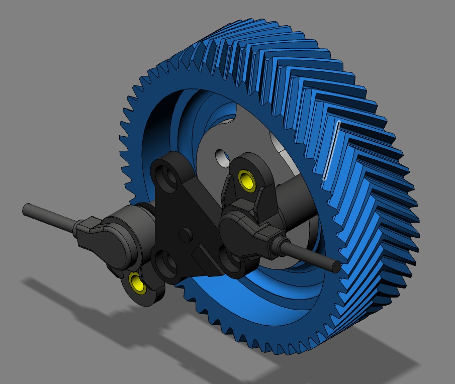
Internal space model, to check how much room is available. This is the sequential ignition variant with a fibre camshaft gear wheel.
Panhard Front Timing Cover Modification 1
18/03/13 18:27 Filed in: Panhard Engine
I have decided to fit electronic ignition to Brian’s engine, and although I can do it a few ways, and have done so in the past, I thought I’d raise the bar a little for Brian’s lump. As I don’t know where the advance curve will want to be, and I didn’t fancy a manual advance & retard system, that could get out of range with disastrous results inadvertently by persons unnamed, it was decided to fit programmable ignition that could cater for twin spark, as well as wasted spark aka Citröen 2CV.
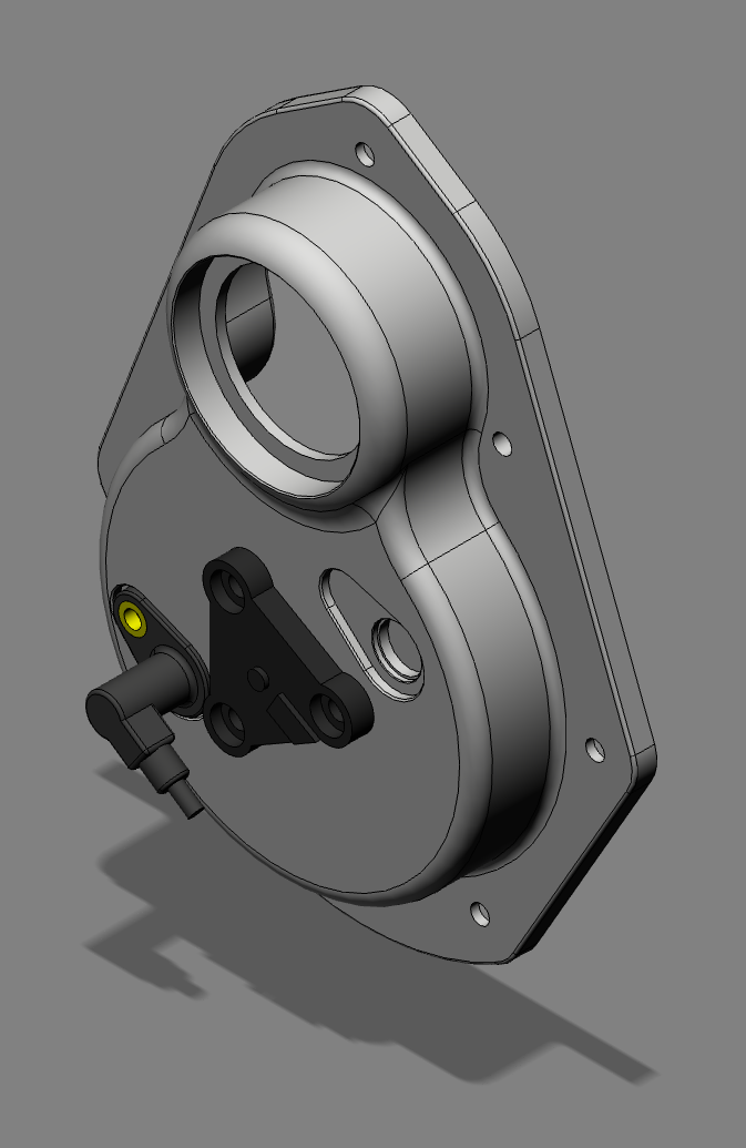
I have identified an ignition system that I could use, that allowed adjustments via a laptop on the fly, which means as you are driving along, unlike TuneECU & my brother’s KTM, but that’s another story. Anyway, after looking at the ignition system some more and exploring how I could build it in neatly to the existing engine, I decided that the front cover was the best choice for my future plans. I need a cam sensor, and I have looked at using the pushrods, the rocker arms and a proximity sensor, but it was all too complicated. I modified Brian’s front cover to take a modern oil seal, and was going to start making a pulley based trigger wheel like I drew some time ago. However the cost of these parts outweighed their usefulness, so I decided Ito revisit the cover again. A couple of hours later, I had a 3D model, based on the dimensions of the original pressed cover,, that had the flexibility to accept any manner of different tooth triggering systems, and a front crankshaft seal that could cater for all ranges of front pulley mods others have done.
A few hiccups, later, one revision to cope with the planned programmable ignition unit, another because of the cost of the sensor loom, meant I’m on the third & hopefully final iteration of the new front cover. It should be more affordable, especially as I have got rid of those over priced Renault connectors. At the moment it is machined from billet, but there is a possibility I can use a casting, however this depends on numbers and whether it is economic to go this type of production process. because you still have to machine the casting, although you do save on roughing out the billet.
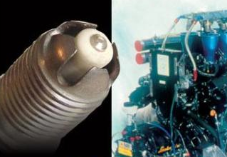
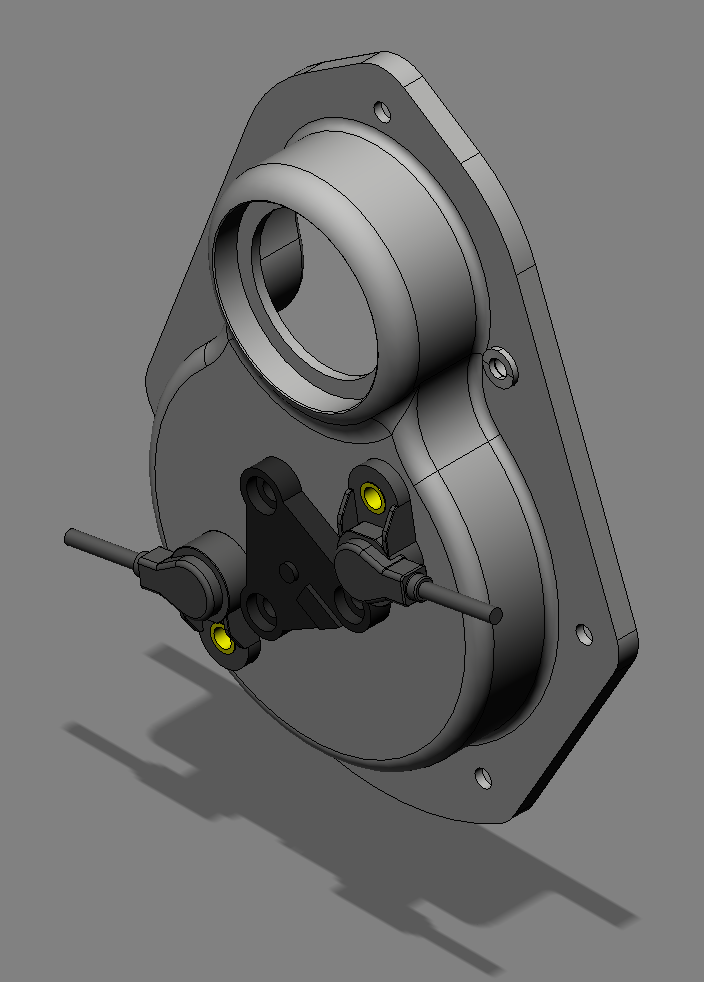
This is the sensor I will be using, which conveniently takes a readily available connector, that doesn’t require exotic crimpers. I have ordered another one for Brian’s engine, as this needs two.
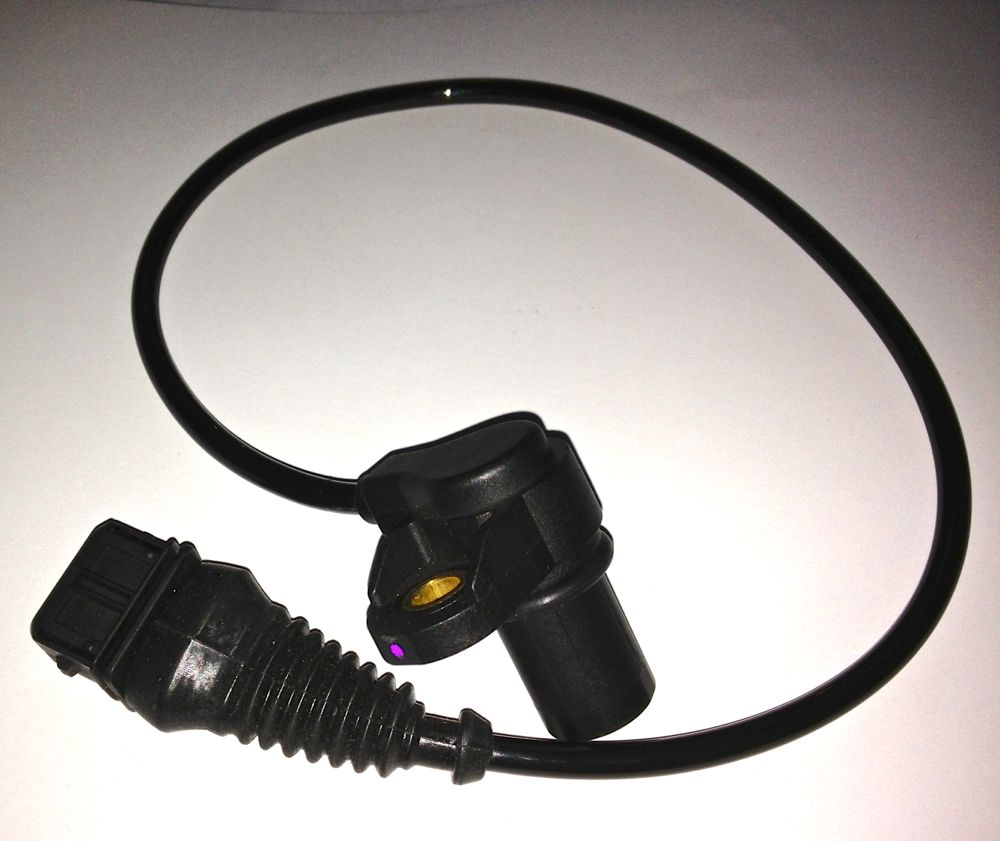
I have identified an ignition system that I could use, that allowed adjustments via a laptop on the fly, which means as you are driving along, unlike TuneECU & my brother’s KTM, but that’s another story. Anyway, after looking at the ignition system some more and exploring how I could build it in neatly to the existing engine, I decided that the front cover was the best choice for my future plans. I need a cam sensor, and I have looked at using the pushrods, the rocker arms and a proximity sensor, but it was all too complicated. I modified Brian’s front cover to take a modern oil seal, and was going to start making a pulley based trigger wheel like I drew some time ago. However the cost of these parts outweighed their usefulness, so I decided Ito revisit the cover again. A couple of hours later, I had a 3D model, based on the dimensions of the original pressed cover,, that had the flexibility to accept any manner of different tooth triggering systems, and a front crankshaft seal that could cater for all ranges of front pulley mods others have done.
A few hiccups, later, one revision to cope with the planned programmable ignition unit, another because of the cost of the sensor loom, meant I’m on the third & hopefully final iteration of the new front cover. It should be more affordable, especially as I have got rid of those over priced Renault connectors. At the moment it is machined from billet, but there is a possibility I can use a casting, however this depends on numbers and whether it is economic to go this type of production process. because you still have to machine the casting, although you do save on roughing out the billet.
This is the sensor I will be using, which conveniently takes a readily available connector, that doesn’t require exotic crimpers. I have ordered another one for Brian’s engine, as this needs two.
Panhard Exhaust Valve Seat Musings
15/03/13 20:15 Filed in: Panhard Engine
This is the third time I have seen exhaust valve issues on Panhard engines. The first one was intermittent loose, the second one dropped out, and now this one in Brian’s engine which was damaged by valve seat recession.
Many years ago, I looked at a loose valve seat and wondered how if these things that were put in using cryogenics they could come loose, because it is rare in modern engines. I used a spreadsheet calculation to plot the relative sizes of the machined seat recess and the insert outside diameter as the temperature rose. Ultimately as the aluminium head gets hotter the dissimilar materials will expand, and loose their interference fit. It happened at around 320ºC, and the percussive action of the valve would almost certainly be moving the seat by then.
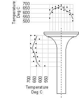
I have been told the expected temperature of the piston will be around 280ºC, but longer advance values from say, a tired distributor will mean the average head temperatures will almost certainly be higher. If you throw in a weak mixture to one cylinder being driven by a good one down the motorway on a hot day for example, and you’ll could easily meet this high temperature condition, but the valve runs much hotter at certain parts of the combustion cycle anyway.
When combustion is initiated the exhaust valve head is heated on the face closest to the piston, and when it opens, the hot combustion products wrap around the valve head, heating the back of the valve head, the seat insert, and the stem. Whereas the inlet valve gets a cooling effect from the fresh charge, the exhaust relies on loosing this heat through the seat insert primarily, which can be as high as 75%. Typically the stem to guide takes the other 25%. These values can vary, depending on what you read, but the primary heat path is the valve seat insert to cylinder head interface. If this has poor conductivity, then the valve seat will not lose its heat, and run hot.
The other side of the coin is other air cooled engines and do they drop valve seats? I don’t know of a problem with Citröen 2CVs, but it was an occasional occurrence with 412 VWs, so perhaps it is the way of things to be. However, cooler oil, non weak mixtures, better ignition control and within specification valve guide clearances should all help reduce the temperatures that the valve seat is exposed to, but is there anything else that could be done.
A quick look into the history books, might reveal a few answers, and they do with exotic materials being used, valve gear exposed to airflow, excessive finning to lose heat, rich mixtures to create a cooling effect, and even reducing head diameter to reduce the surface area exposed to the combustion process. Anything else?
Here’s a Panhard valve seat insert, and below that is the same Panhard exhaust seat insert & a modern equivalent from a Harley Davidson…spot the difference? The clue is in the sides.
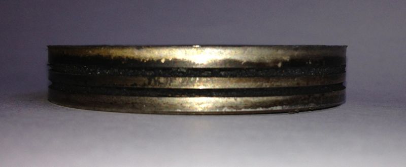
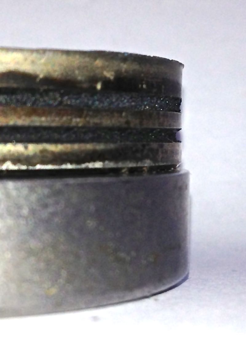
Notice the carbon deposits from the combustion products caking up the sides of the seat.
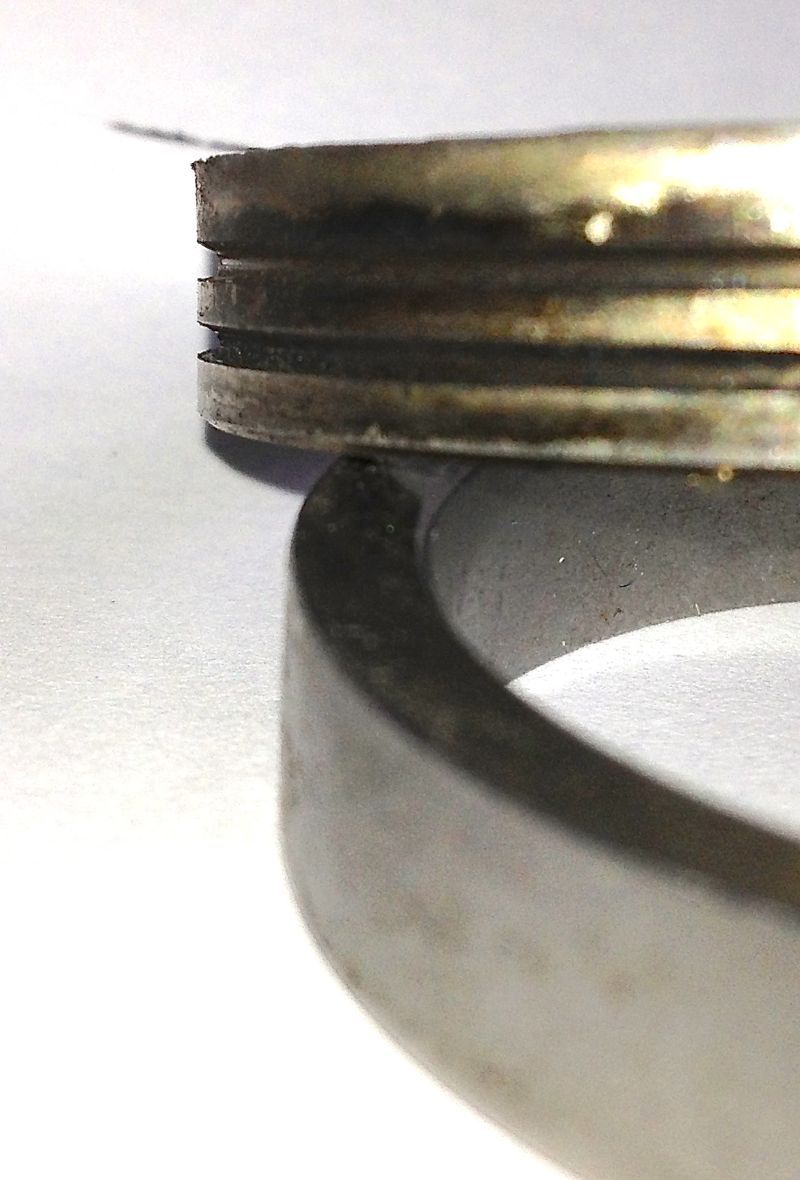
Panhard valve seat inserts, have peripheral grooves in them, nearly every other seat has smooth sides to maximise the contact area, so perhaps this explains the issue more than anything else. Panhard valve seats should be replaced with smooth bore equivalents, and possible have slightly more interference fit.
Brian’s engine will have this fitted to his affected cylinder.
Many years ago, I looked at a loose valve seat and wondered how if these things that were put in using cryogenics they could come loose, because it is rare in modern engines. I used a spreadsheet calculation to plot the relative sizes of the machined seat recess and the insert outside diameter as the temperature rose. Ultimately as the aluminium head gets hotter the dissimilar materials will expand, and loose their interference fit. It happened at around 320ºC, and the percussive action of the valve would almost certainly be moving the seat by then.
I have been told the expected temperature of the piston will be around 280ºC, but longer advance values from say, a tired distributor will mean the average head temperatures will almost certainly be higher. If you throw in a weak mixture to one cylinder being driven by a good one down the motorway on a hot day for example, and you’ll could easily meet this high temperature condition, but the valve runs much hotter at certain parts of the combustion cycle anyway.
When combustion is initiated the exhaust valve head is heated on the face closest to the piston, and when it opens, the hot combustion products wrap around the valve head, heating the back of the valve head, the seat insert, and the stem. Whereas the inlet valve gets a cooling effect from the fresh charge, the exhaust relies on loosing this heat through the seat insert primarily, which can be as high as 75%. Typically the stem to guide takes the other 25%. These values can vary, depending on what you read, but the primary heat path is the valve seat insert to cylinder head interface. If this has poor conductivity, then the valve seat will not lose its heat, and run hot.
The other side of the coin is other air cooled engines and do they drop valve seats? I don’t know of a problem with Citröen 2CVs, but it was an occasional occurrence with 412 VWs, so perhaps it is the way of things to be. However, cooler oil, non weak mixtures, better ignition control and within specification valve guide clearances should all help reduce the temperatures that the valve seat is exposed to, but is there anything else that could be done.
A quick look into the history books, might reveal a few answers, and they do with exotic materials being used, valve gear exposed to airflow, excessive finning to lose heat, rich mixtures to create a cooling effect, and even reducing head diameter to reduce the surface area exposed to the combustion process. Anything else?
Here’s a Panhard valve seat insert, and below that is the same Panhard exhaust seat insert & a modern equivalent from a Harley Davidson…spot the difference? The clue is in the sides.
Notice the carbon deposits from the combustion products caking up the sides of the seat.
Panhard valve seat inserts, have peripheral grooves in them, nearly every other seat has smooth sides to maximise the contact area, so perhaps this explains the issue more than anything else. Panhard valve seats should be replaced with smooth bore equivalents, and possible have slightly more interference fit.
Brian’s engine will have this fitted to his affected cylinder.
Panhard Front Oil Seal Modification
13/03/13 18:55 Filed in: Panhard Engine
I always intended to fit a modern oil seal to Brian’s engine, but I was going to make a new pulley arrangement, however the ignition has taken another direction lately, so I don’t need the crankshaft triggering I was going to use, but more about that one later.
The original solution is to use a piston ring type seal
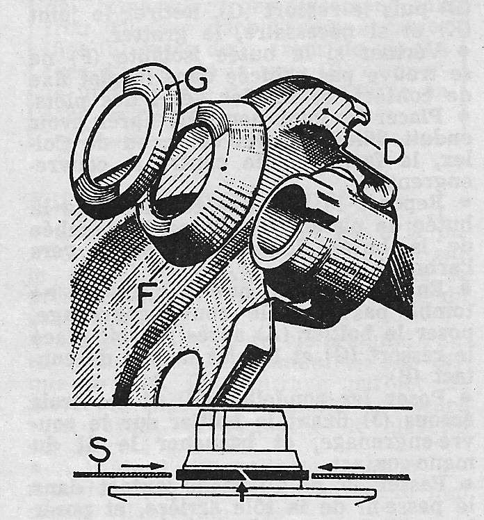
There is a groove in the front pulley (arrowed) to accept a piston ring type seal, with a hardened surface in the cover for it to rotate in.
There are a few ways to create a seal here, the easiest at the moment is to do this. Place the front pulley in a lathe, aka damp Colchester
i
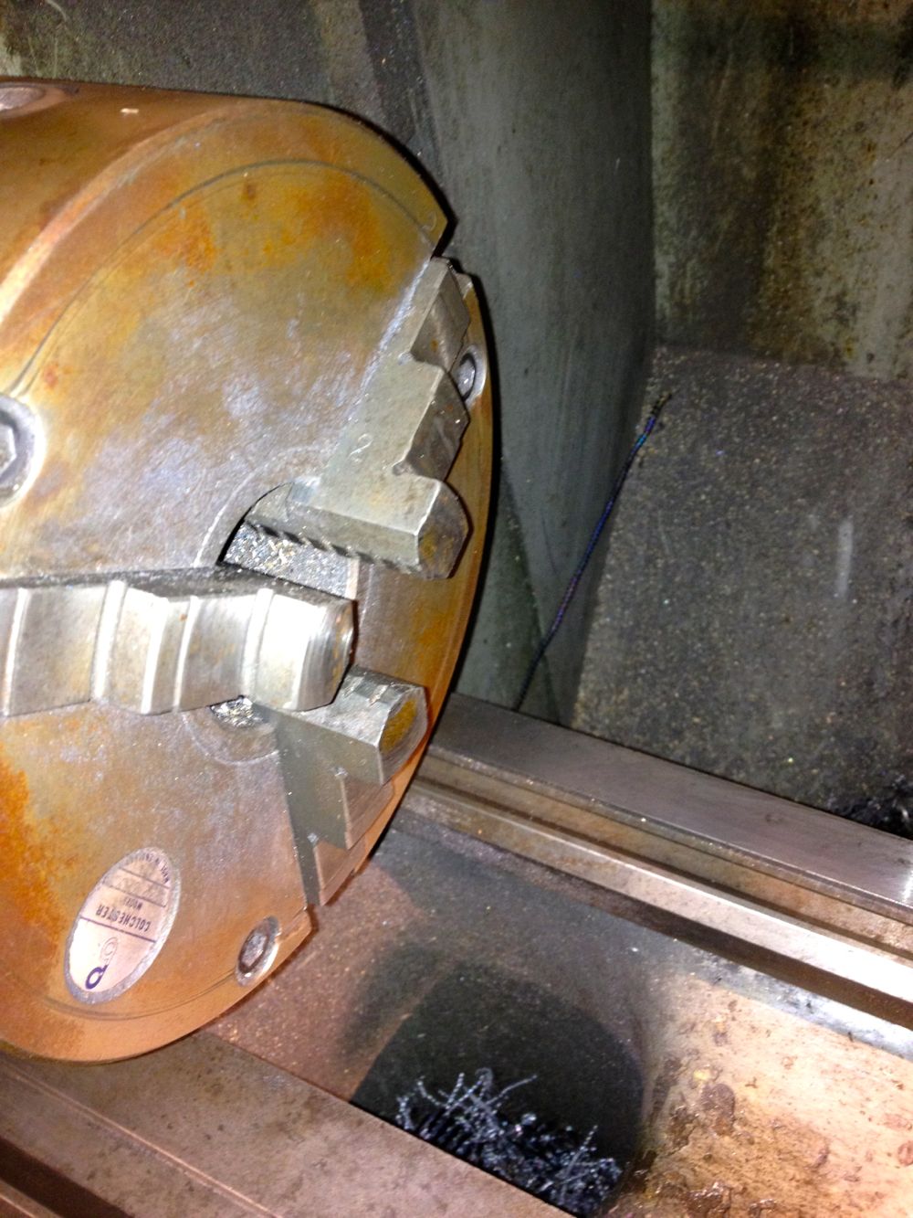
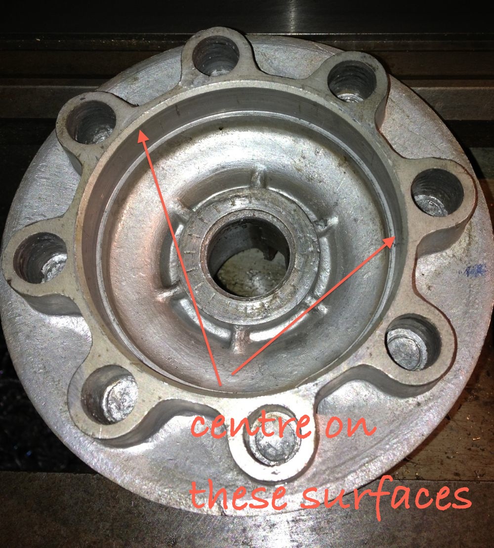
Check it’s running true, and machine to 40.02 mm, but don’t worry if you go too small as bearing retainer will save your bacon.
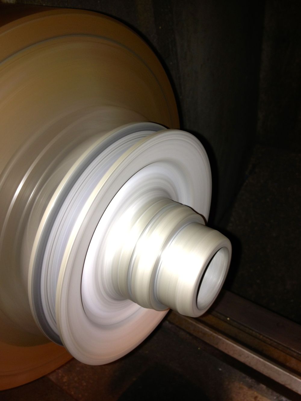
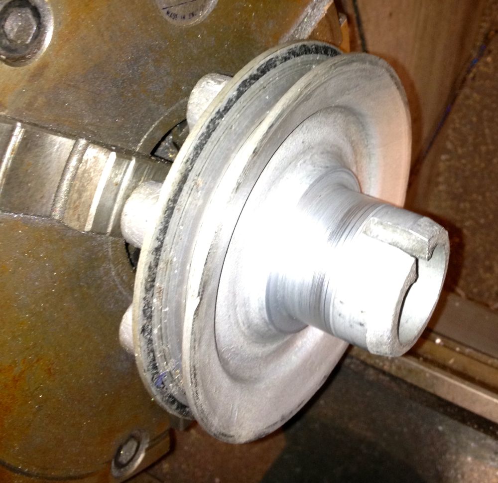
Install the 40 x 45 x 17 inner ring
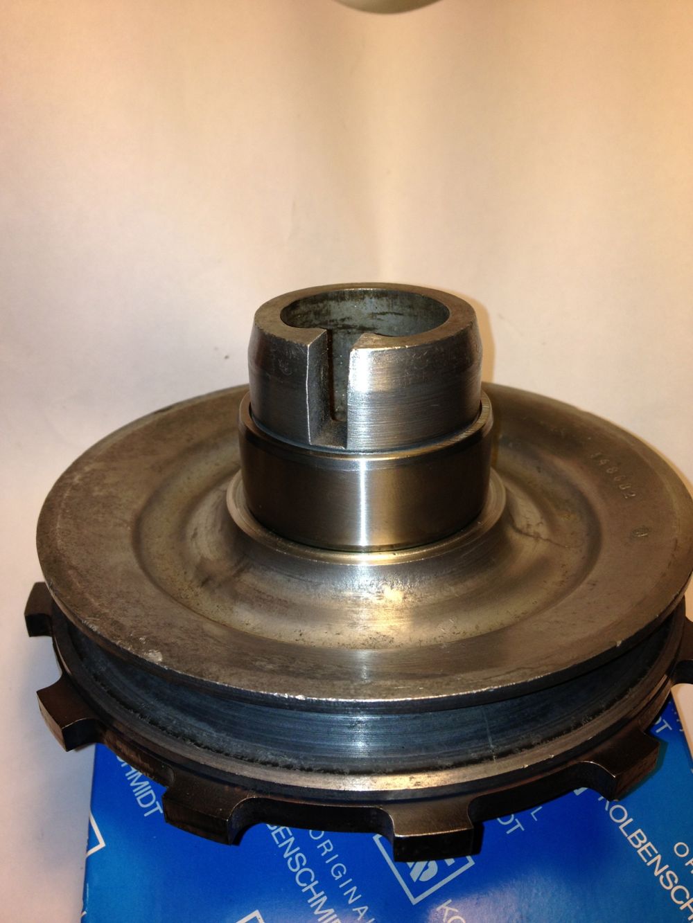
Next up modify the timing cover, I used a local engineering company to open up the hole to Ø52mm, the idea being I could use a 42 x 52 x 4, 5, 7 or 8 mm deep R23 oil seal. These are available in Viton in the smaller widths, but Nitrile or NBR is adequate for this diameter. The 5mm is shown, but I am changing this to the 8mm version when it arrives.
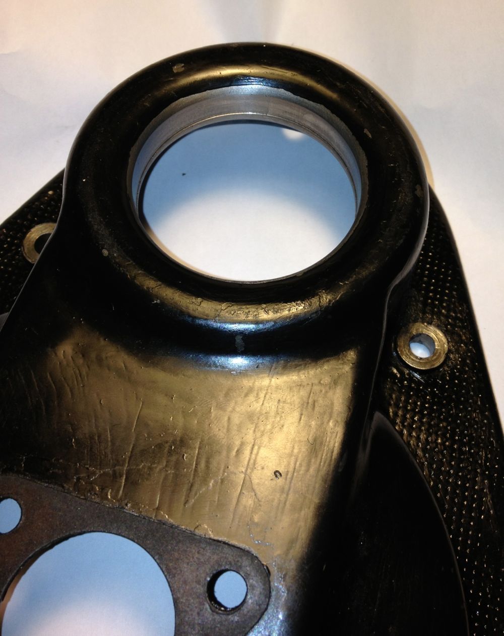
There is a slight step, which acts a s a seal stop when fitting, which you can see in the close up.
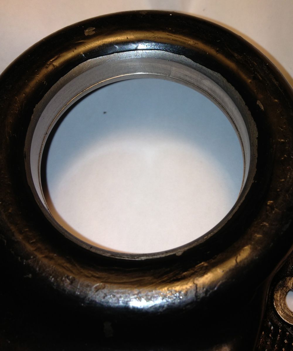
To make it easier to fit the seal square and not push it in so far I made a stepped mandrel out of some scrap ABS.
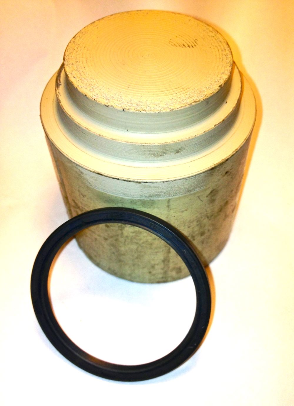
To fit the seal, place on the tool, and then push into place.
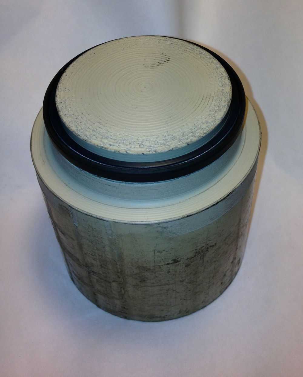
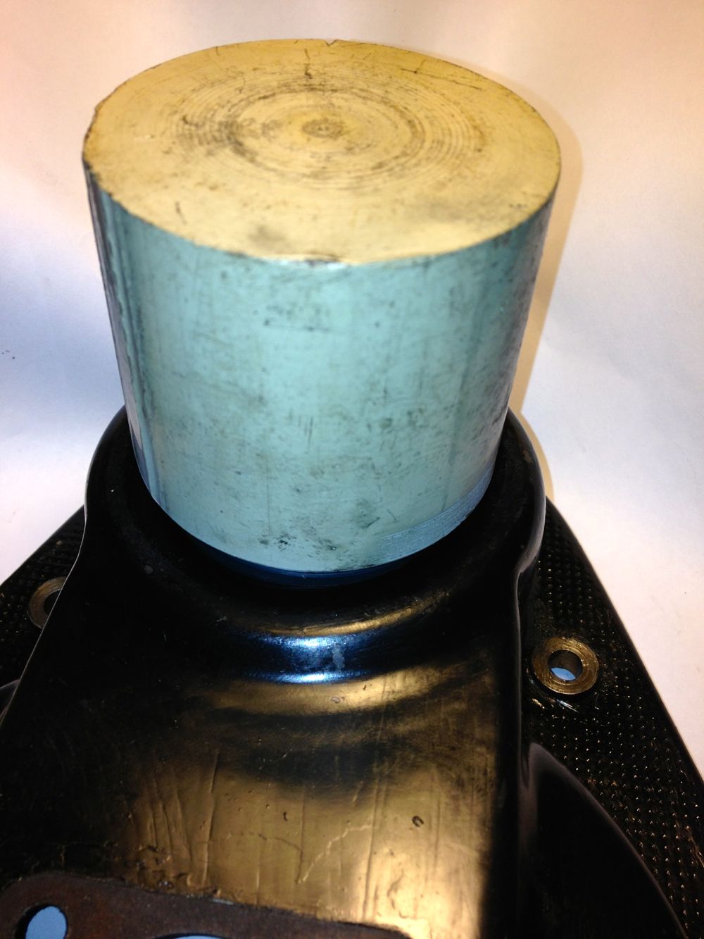
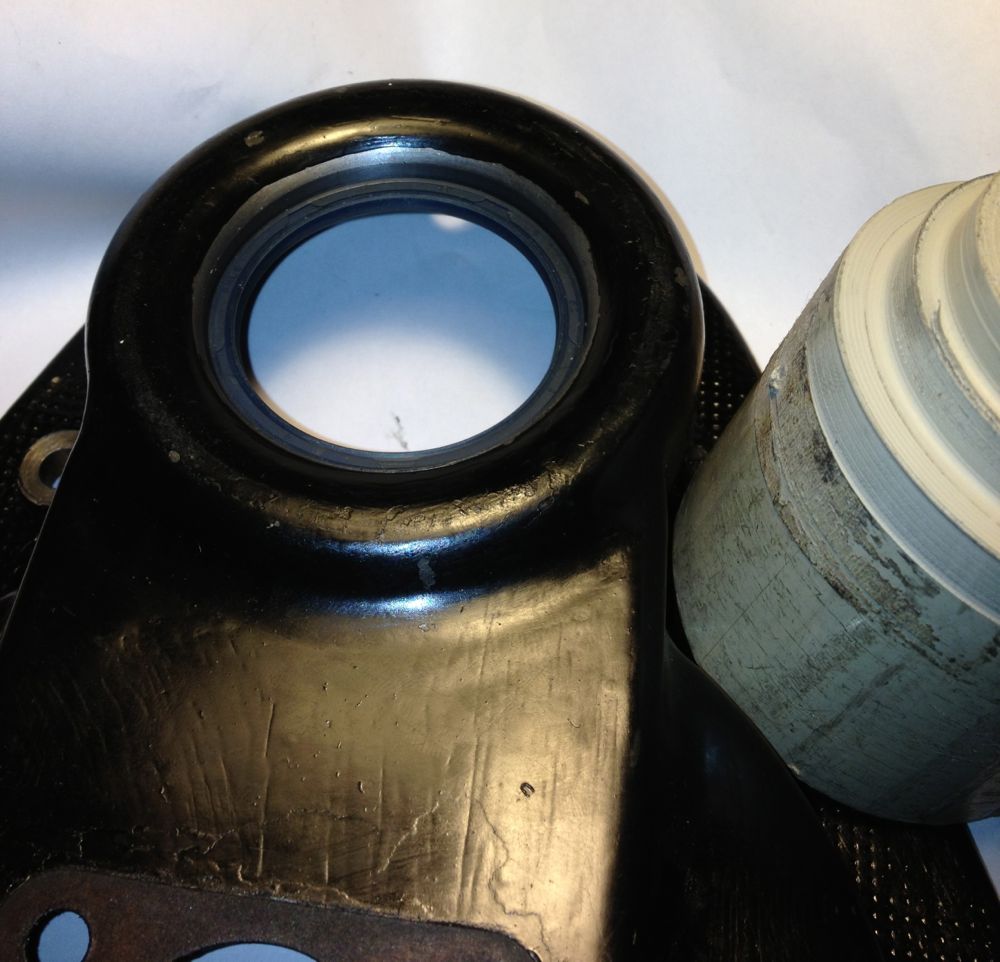
Job done.
Note I will not be fitting the slingers (G & F in the diagram at the start of the blog) inside the timing cover, as the oil mist and splash lubrication to the gears will lubricate the seal, and stop it sticking or drying out.
The original solution is to use a piston ring type seal
There is a groove in the front pulley (arrowed) to accept a piston ring type seal, with a hardened surface in the cover for it to rotate in.
There are a few ways to create a seal here, the easiest at the moment is to do this. Place the front pulley in a lathe, aka damp Colchester
i
Check it’s running true, and machine to 40.02 mm, but don’t worry if you go too small as bearing retainer will save your bacon.
Install the 40 x 45 x 17 inner ring
Next up modify the timing cover, I used a local engineering company to open up the hole to Ø52mm, the idea being I could use a 42 x 52 x 4, 5, 7 or 8 mm deep R23 oil seal. These are available in Viton in the smaller widths, but Nitrile or NBR is adequate for this diameter. The 5mm is shown, but I am changing this to the 8mm version when it arrives.
There is a slight step, which acts a s a seal stop when fitting, which you can see in the close up.
To make it easier to fit the seal square and not push it in so far I made a stepped mandrel out of some scrap ABS.
To fit the seal, place on the tool, and then push into place.
Job done.
Note I will not be fitting the slingers (G & F in the diagram at the start of the blog) inside the timing cover, as the oil mist and splash lubrication to the gears will lubricate the seal, and stop it sticking or drying out.
Panhard Exhaust Valve Seat Recession
23/02/13 14:20 Filed in: Panhard Engine
I always thought that Panhard valve seats were immune to valve seat recession. I was just stripping down Brian’s rear cylinder, when I noticed the exhaust valve sticking when I removed the collets. This is the reason why.
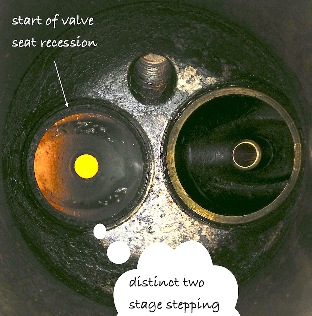
The exhaust valve had receded into the head by about 1mm in places, and the seat now looks like it has two 45 degree faces cut in it, so it looks like a new valve seat is in order, or it might be quicker to swap out the cylinder. I have a valve seat, but it means heating the cylinder to about 380ºC, which is when the differential expansion rates should loose their interference fit, but it looks like I will have to do the valve guide too, as it’s rocking once the valve is off its seat.
Looks like the engine liked it oil, but it did have a broken piston ring, so that won’t have helped. Time for some barbecue cleaner
Panhard Cylinder Liner Rebore Update 10
02/02/13 19:42 Filed in: Panhard Engine
I am finally getting there with the cylinder liner reconditioning. Just experimenting with a few test liners before committing myself to doing Brian’s, and this is the result so far, but without being plateau honed as yet. I am using the liner clamp rig I made last weekend to hold the liner and the bores are honing up nicely.
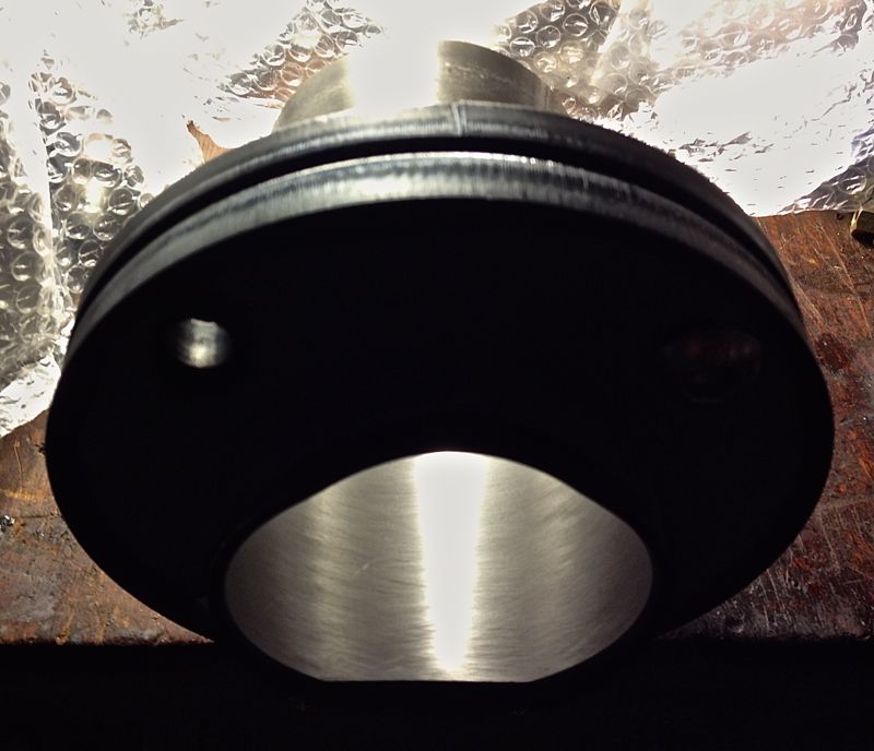
Next weekend, I should be able to drop `Brian’s liners out of his cylinders, and get started on them. I need to wait for the other honing stones to come from the USA, as the first set are too big. Never looked at the small print, and although Sunnen AN111 stones can fit in a Delapena M2 head, there are variations in the rack lengths of the stones, and the minimum size of the last batch I got are just too big at 3.5”, especially when I should have got the 2.7-4.1” versions :doh
Next weekend, I should be able to drop `Brian’s liners out of his cylinders, and get started on them. I need to wait for the other honing stones to come from the USA, as the first set are too big. Never looked at the small print, and although Sunnen AN111 stones can fit in a Delapena M2 head, there are variations in the rack lengths of the stones, and the minimum size of the last batch I got are just too big at 3.5”, especially when I should have got the 2.7-4.1” versions :doh
Panhard Cylinder Liner Rebore Update 9
26/01/13 19:54 Filed in: Panhard Engine
Now that I can bore the cylinder liners, I need to make a jig to hold the liners whilst they are being honed. If you use an annular ring clamp, a dummy cylinder, this will always squeeze the liner, and cause distortion,which is exactly want you don’t want.
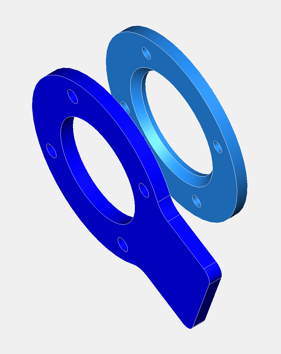
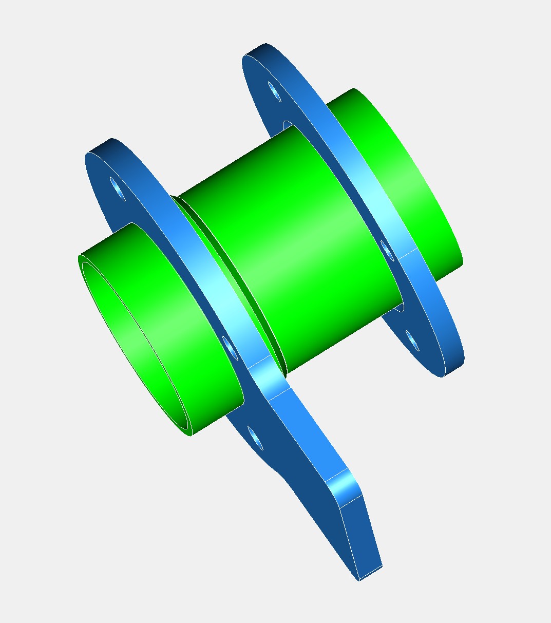
To get around this problem I have made an axial clamping system that uses the original abutments on the external faces of the liner. I drew the parts on the computer, and then had them laser cut from mild steel plate. After a few moments on the lathe, they looked like the sketch above, and a quick test with a previously machined liner and some oversize M12 screws, proved the clamping was secure and didn’t affect the internal bore diameter.
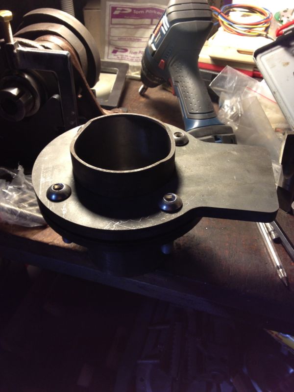
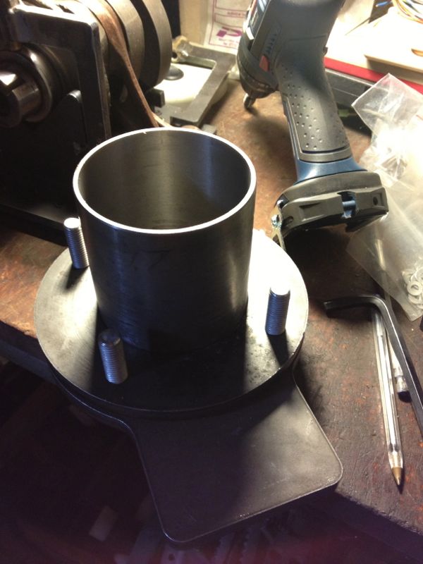
Hopefully, I should get the honing stones from the USA this week, and then I can transform the old worn cylinders in Brian’s engine, into perfectly machined and honed oversized replacements, that match the new pistons.
To get around this problem I have made an axial clamping system that uses the original abutments on the external faces of the liner. I drew the parts on the computer, and then had them laser cut from mild steel plate. After a few moments on the lathe, they looked like the sketch above, and a quick test with a previously machined liner and some oversize M12 screws, proved the clamping was secure and didn’t affect the internal bore diameter.
Hopefully, I should get the honing stones from the USA this week, and then I can transform the old worn cylinders in Brian’s engine, into perfectly machined and honed oversized replacements, that match the new pistons.
Panhard Crankshaft Truing
04/11/12 17:30 Filed in: Panhard Engine
As I said in my blog, it was a little too cold to work in the attic today, so I spent a few hours at the workshop. I had some bespoke round bar stock lying around, that I was planning on making a crankshaft truing tool, but I wasn’t ready to mess with crankshafts whilst I was doing all the liner related work. Anyway that is virtually done now, bar a phone call to the piston company, so it was time to jump on the Elliot mill, and make a new tool.
This is what I had in mind, but I was limited by what bullnose endmills I had, so I used a smaller radius than I would have liked.
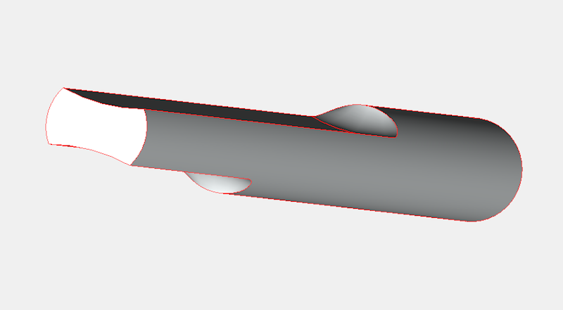
After a couple of hours, it was done. It took longer because I needed to keep checking by placing it in a crankshaft making sure I wasn’t taking too much metal away.
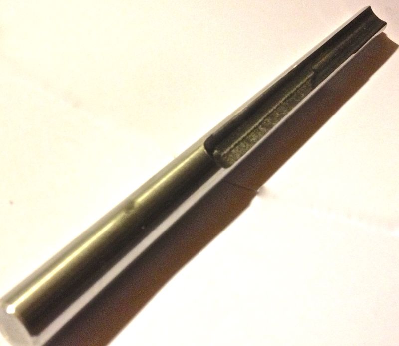
As I was making it I was testing it in Martin McClarence’s crankshaft that had turned. Fortunately it was the rear web that had moved, so I could refine the size of the tool to fit it.
Imagine my surprise when i got home and tested Brian’s crankshaft, and I discovered this had moved ever so slightly on the front web. I knew the rear web had moved, but interestingly it had been pulled outwards, because the crankshaft was too long between the main bearings. I can only put this down to rear bearing movement, due to a shimming error in the rear bearing backplate, but this was assisted by the oscillating crank due to the misalignment.
Anyway, the front web of the crankshaft is true now, after giving it a very hefty whack with the #4 Thor copper hammer, but the rear web is ever so slightly out. Next up on the crank is to press it together again, so the rear web has the correct connecting rod clearance, and then I’ll true the crankshaft up finally.
This is what I had in mind, but I was limited by what bullnose endmills I had, so I used a smaller radius than I would have liked.
After a couple of hours, it was done. It took longer because I needed to keep checking by placing it in a crankshaft making sure I wasn’t taking too much metal away.
As I was making it I was testing it in Martin McClarence’s crankshaft that had turned. Fortunately it was the rear web that had moved, so I could refine the size of the tool to fit it.
Imagine my surprise when i got home and tested Brian’s crankshaft, and I discovered this had moved ever so slightly on the front web. I knew the rear web had moved, but interestingly it had been pulled outwards, because the crankshaft was too long between the main bearings. I can only put this down to rear bearing movement, due to a shimming error in the rear bearing backplate, but this was assisted by the oscillating crank due to the misalignment.
Anyway, the front web of the crankshaft is true now, after giving it a very hefty whack with the #4 Thor copper hammer, but the rear web is ever so slightly out. Next up on the crank is to press it together again, so the rear web has the correct connecting rod clearance, and then I’ll true the crankshaft up finally.
Panhard Cylinder Liner Rebore Update 8
03/11/12 15:39 Filed in: Panhard Piston | Whatton
I was dropping something off at the workshop, and so I thought I’d look at the cylinder bore sizing with respect to temperature.
I wanted a rough idea, as too how much the cylinder would grow, and at what temperature could I expect the tapered bore to become parallel. I devised a really simple experiment, using a soft flame large propane torch ( no time for an oil bath etc), an infra red thermometer, and a three point micrometer, I quickly took snapshots of the sizes I was seeing on the micrometer, as I increased the temperature.
The idea was I’d measure the liner cold (today 5ºC), then about 50ºC, 100ºC and finally about 120ºC. These were just ball park figures, and the blow torch would be aimed around the cylinder finning roughly at the combustion chamber position. The temperatures were taken on the same spot, a nice black area, and the twin laser beams were focussed on this consistently. The cylinder was warmed past the temperature required and then allowed to drop to reach the desired test temperature. This way the heat would be soaking into the components more consistently.
As it was a little warmer, than yesterday, the cold bore at the top of the liner measured
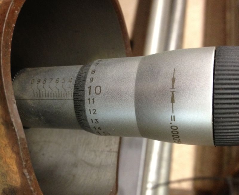
Next the cylinder was warmed up to just over 50ºC, and new readings taken, but each time I rested the micrometer in the setting ring to dissipate any heat build up caused by taking the reading. the reading shows the new top bore size, around 0.0025” larger on just 50ºC.
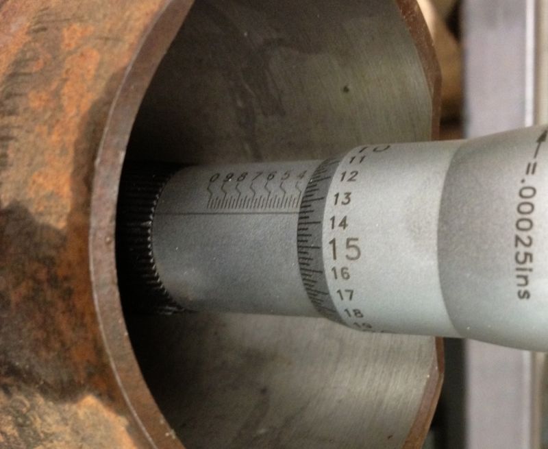
The bit just a bit further down was measured at about 0.0035” larger.
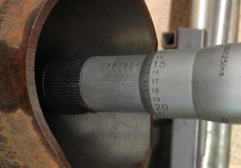
So then the cylinder was heated to just over 100ºC, and more measurements taken, and the top of the liner was reading about “16” now( another 2.5 thou larger). The middle of the liner had opened up further too, and even more lower down, as shown below
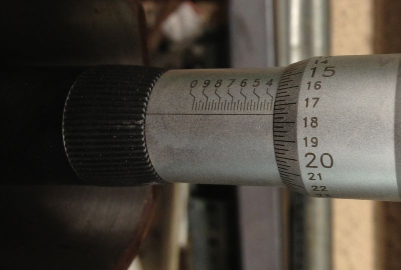
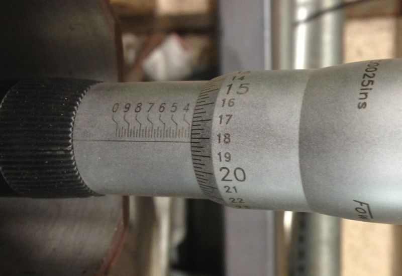
Picture below showing the setting ring and temperature at the moment of measuring.
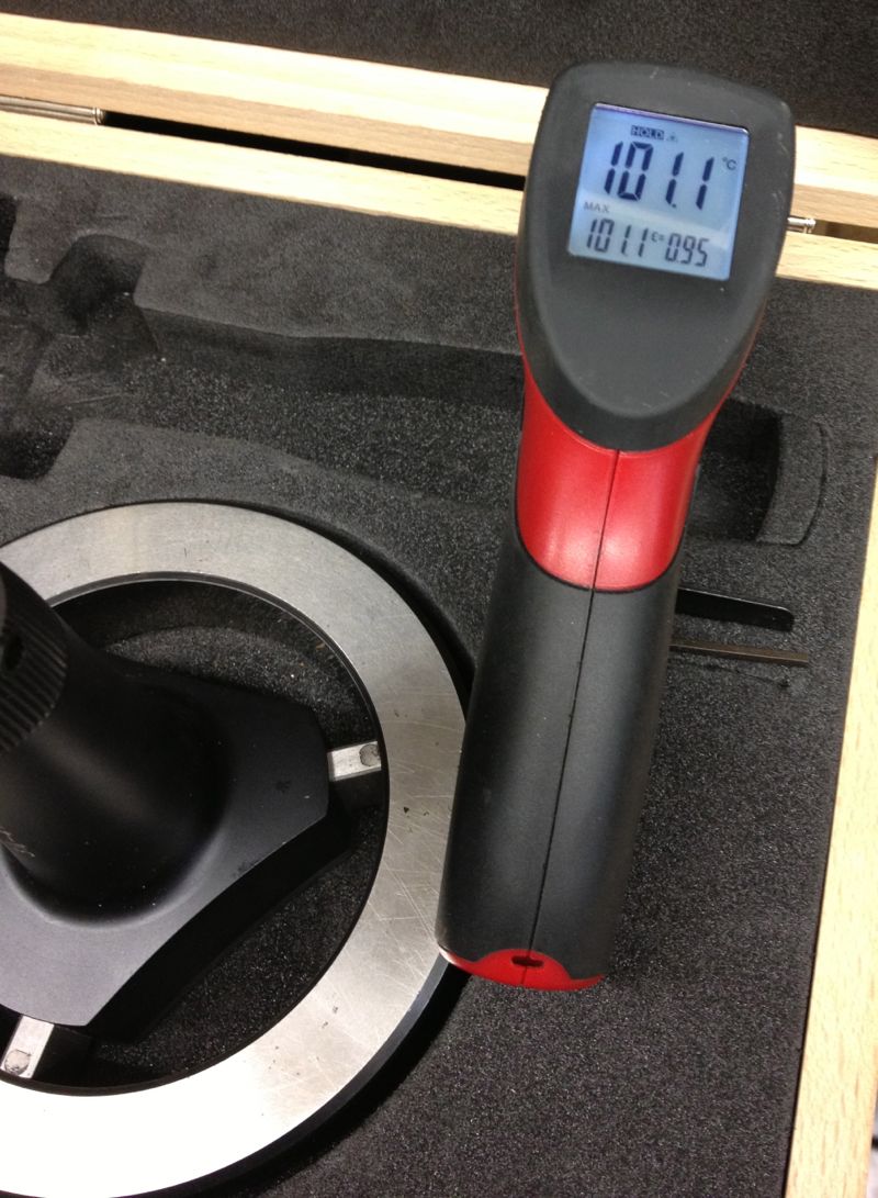
Then I heated the cylinder to about 130ºC, and let it cool slightly, and also took more measurements at the following temperature (116ºC) and then I noticed this!
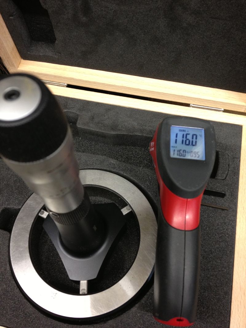
Top of liner closest to the combustion chamber measured “18” the same as the middle of the liner and the base of the liner was nearly the same, as the two images show.
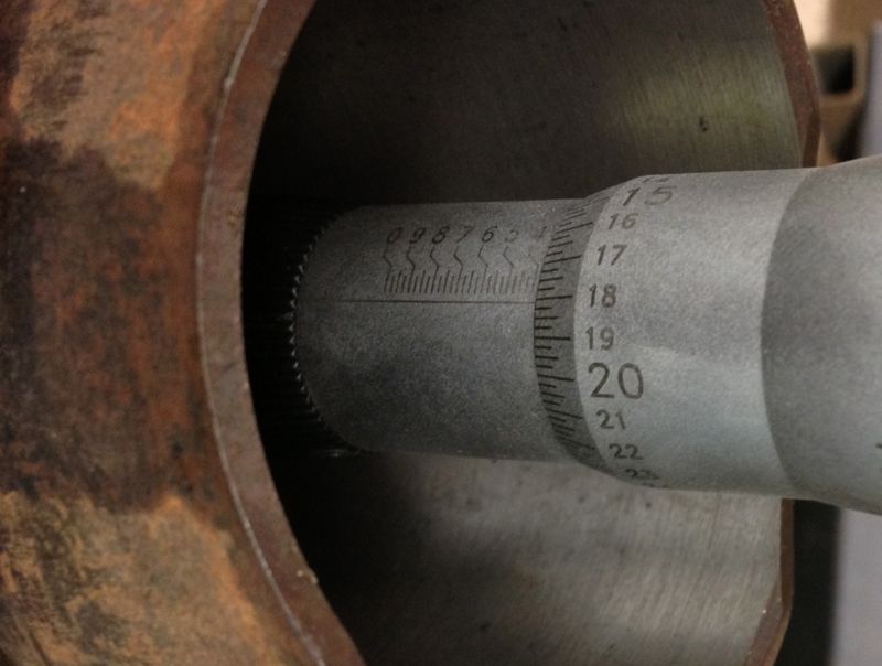
Middle measurement was blurred, but you can see it is on the “18” mark
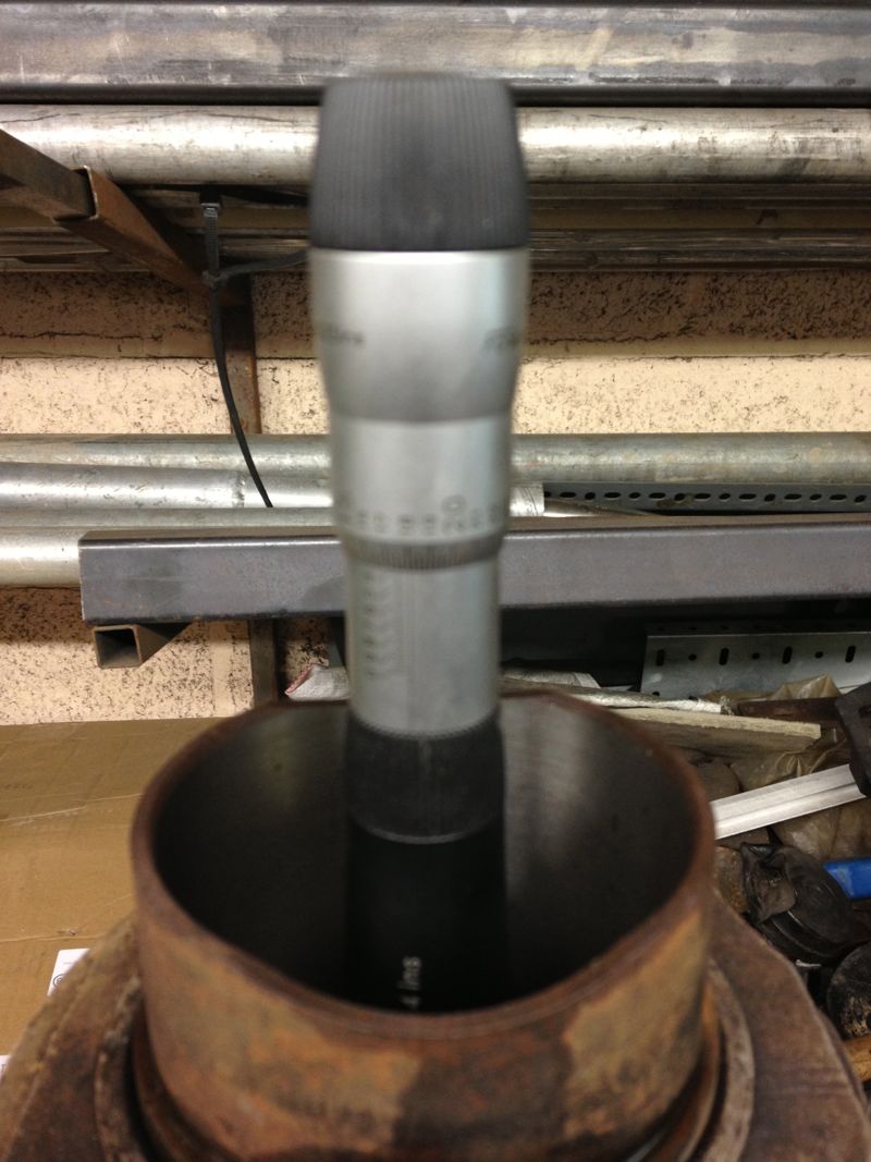
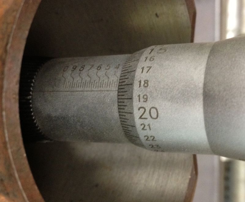
Conclusion, at around 120ºC the cylinder casting expands enough to become parallel, so now I have a figure I can work from to set my piston clearances too.
I wanted a rough idea, as too how much the cylinder would grow, and at what temperature could I expect the tapered bore to become parallel. I devised a really simple experiment, using a soft flame large propane torch ( no time for an oil bath etc), an infra red thermometer, and a three point micrometer, I quickly took snapshots of the sizes I was seeing on the micrometer, as I increased the temperature.
The idea was I’d measure the liner cold (today 5ºC), then about 50ºC, 100ºC and finally about 120ºC. These were just ball park figures, and the blow torch would be aimed around the cylinder finning roughly at the combustion chamber position. The temperatures were taken on the same spot, a nice black area, and the twin laser beams were focussed on this consistently. The cylinder was warmed past the temperature required and then allowed to drop to reach the desired test temperature. This way the heat would be soaking into the components more consistently.
As it was a little warmer, than yesterday, the cold bore at the top of the liner measured
Next the cylinder was warmed up to just over 50ºC, and new readings taken, but each time I rested the micrometer in the setting ring to dissipate any heat build up caused by taking the reading. the reading shows the new top bore size, around 0.0025” larger on just 50ºC.
The bit just a bit further down was measured at about 0.0035” larger.
So then the cylinder was heated to just over 100ºC, and more measurements taken, and the top of the liner was reading about “16” now( another 2.5 thou larger). The middle of the liner had opened up further too, and even more lower down, as shown below
Picture below showing the setting ring and temperature at the moment of measuring.
Then I heated the cylinder to about 130ºC, and let it cool slightly, and also took more measurements at the following temperature (116ºC) and then I noticed this!
Top of liner closest to the combustion chamber measured “18” the same as the middle of the liner and the base of the liner was nearly the same, as the two images show.
Middle measurement was blurred, but you can see it is on the “18” mark
Conclusion, at around 120ºC the cylinder casting expands enough to become parallel, so now I have a figure I can work from to set my piston clearances too.
Panhard Cylinder Liner Rebore Update 7
02/11/12 20:27 Filed in: Panhard Piston
HOW A PANHARD CYLINDER IS TAPERED
A Panhard air cooled twin has tapered bores, but the cylinder casting internal bore is parallel, the liner or sleeve is parallel externally, and all the new old stock liners have been as near as damn it parallel internally. So what is causing the taper?
Here’s the answer
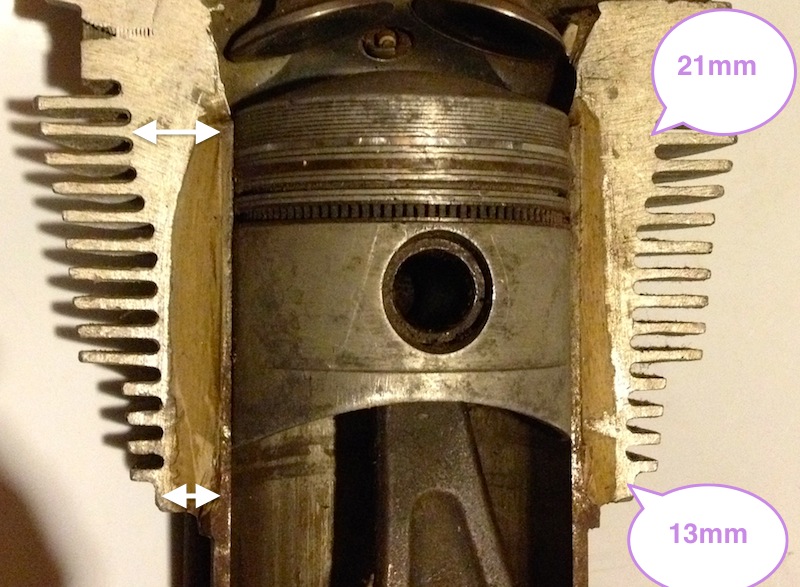
The cylinder casting has variable wall thicknesses, and is much thicker at the top of the liner than it is at the base of the casting, which means for any given interference fit, the base of the casting will give more than the top, so the liner is squeezed prorate more at the top than the bottom.
Really simple and it’s just physics. By varying the wall thickness to suit the likely temperature gradient, you can achieve tighter running clearances by tapering the bore inwards when cold. If this is combined with modern piston technology & manufacturing a quieter, more powerful air cooled engine will be the result.
A Panhard air cooled twin has tapered bores, but the cylinder casting internal bore is parallel, the liner or sleeve is parallel externally, and all the new old stock liners have been as near as damn it parallel internally. So what is causing the taper?
Here’s the answer
The cylinder casting has variable wall thicknesses, and is much thicker at the top of the liner than it is at the base of the casting, which means for any given interference fit, the base of the casting will give more than the top, so the liner is squeezed prorate more at the top than the bottom.
Really simple and it’s just physics. By varying the wall thickness to suit the likely temperature gradient, you can achieve tighter running clearances by tapering the bore inwards when cold. If this is combined with modern piston technology & manufacturing a quieter, more powerful air cooled engine will be the result.
Panhard Cylinder Liner Rebore Update 6
28/10/12 15:08 Filed in: Panhard Piston | Whatton
Yesterday, I machined a couple of test liners from an early Dyna engine, and after inspecting them, I decided I would do a test fit in the aluminium cylinder to see what difference there was in the bore diameter due to the interference fit.
After warming up the bare cylinder with the big propane torch, I placed the cylinder in, and rotated it into the correct position (these liners have cut outs for the crankshaft webs).
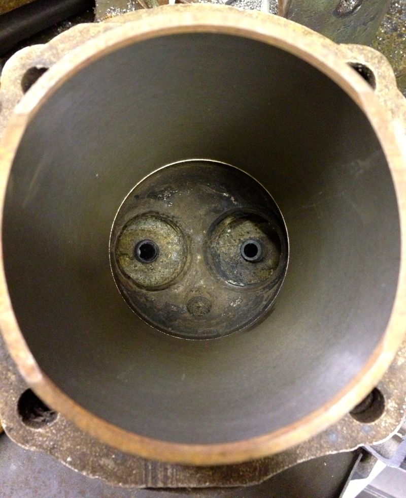
Once it was cool, I decided to take a remeasure, and see how the dimensions compared.
I started off with this measurement from yesterday, but when the sleeve or liner was placed in the cylinder I got the measurement in the second picture below.
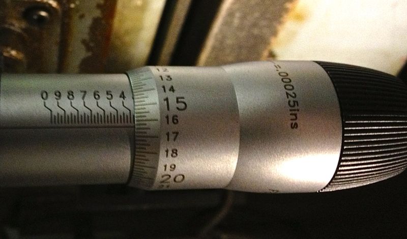
To be honest, I thought the cylinder was larger than this picture above when I measured it this morning at around the “17.25” mark, which represents 3.36725”, but for some reason I have mislaid the picture.
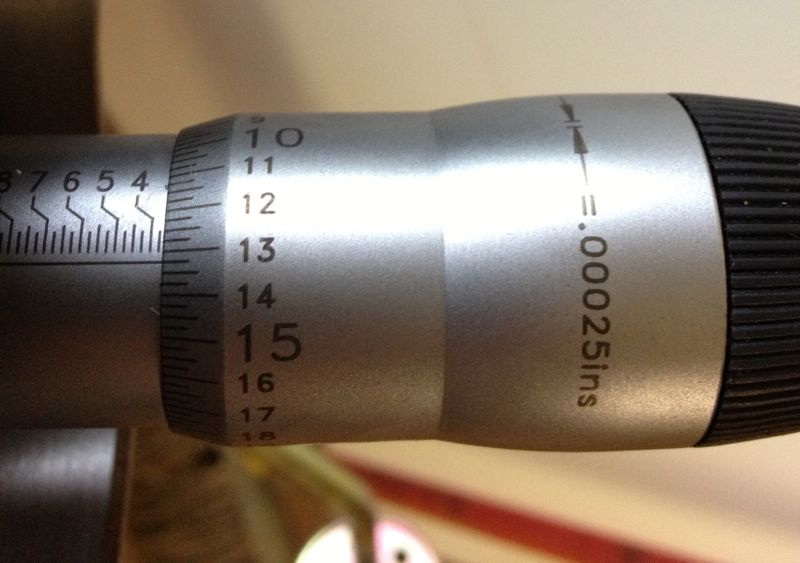
Either way this represents a 0.003”-0,004” squeeze depending what picture I look at, and as I moved the micrometer out of the cylinder and took further measurements along the way, I got the following…
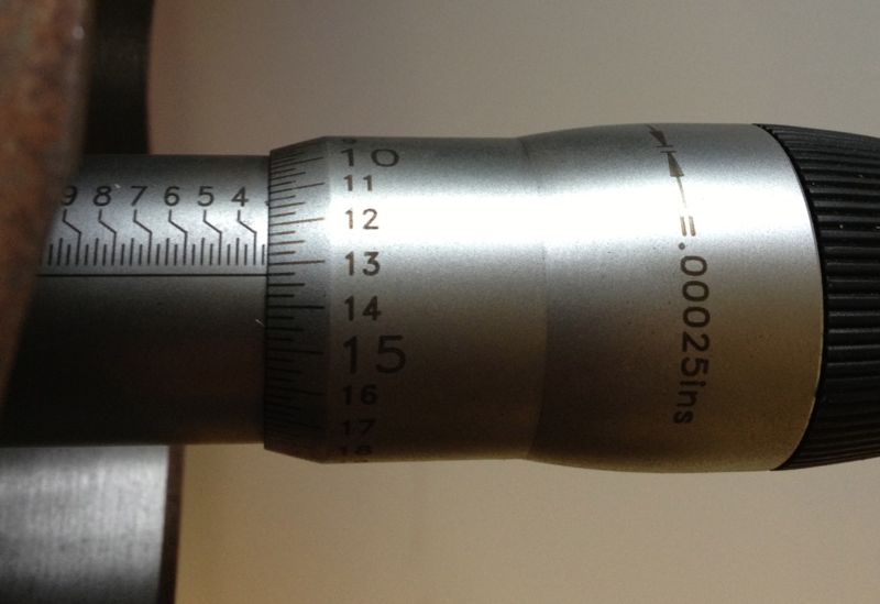
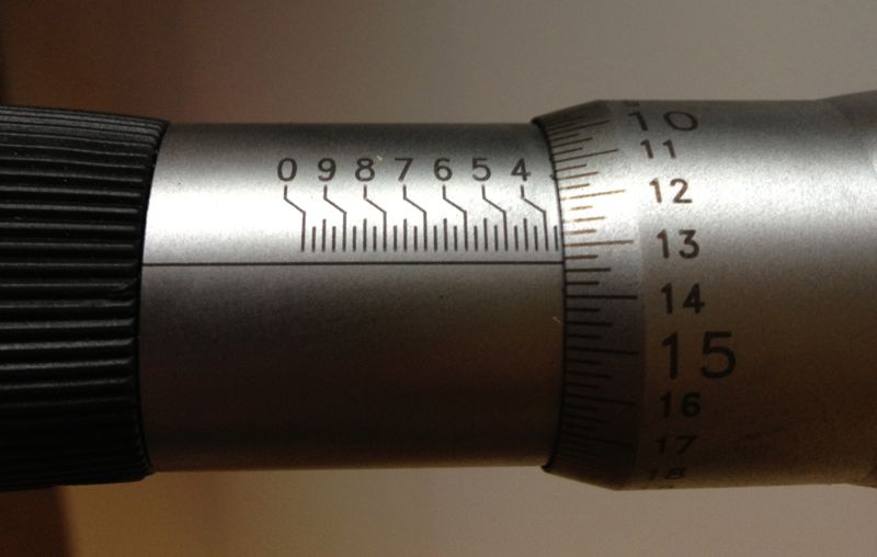
As the liner left the grip of the cylinder the sleeve opened up, as shown below.
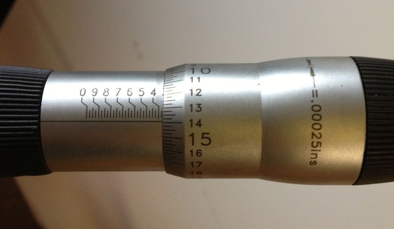
At the skirt perimeter it measured even bigger still at 3.36775”, but this isn’t a huge deal, but it is interesting that a parallel bored liner deflects this much.
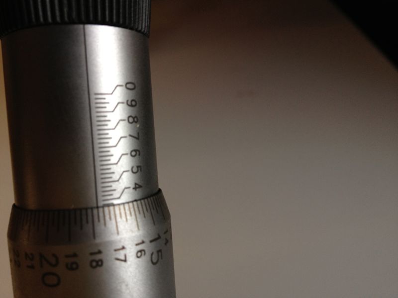
So yet again, we have the issue of an interference fit and the folklore surrounding a tapered bore. The last liner I machined using the Whatton actually produced a tapered bore, and the taper runs in the right direction too, because it is smallest at the hottest end.
I now know how to achieve this, and after playing with the Whatton some more, i have ascertained why it is happening. Anyway, it is an accidental product of my curiosity, and what relevance it has on real world engines is unproven. I will explore this option when the engine dyno test facility is up and running, to see if it is beneficial.
On the subject of taper, here are two pictures of a bare piston in the cylinder liner, but turned through 90º. Notice the difference in the resting height, this is due to the ovality of the piston, and the bore being smaller than the pistons nominal diameter of 85.4mm or 3.3622”
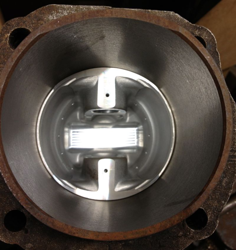
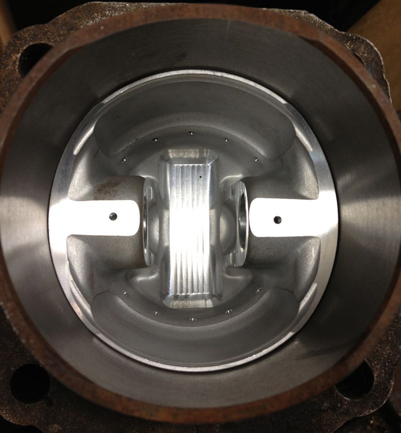
Obviously with the interference fit, the liner is slightly smaller than the expected size, as it reads 3.36320” diameter over it’s running surface, and it’s recommended value of 85.5mm equates to 3.36614”, so it’s 0.003“ undersize, or operating on a 0.001” piston to bore clearance. Actually, in modern 2 valve race engines, with very light pistons and a better spec liner material, I have seen 0.0015” clearance on an air-cooled V twin.
It did seize, because of a fuelling error, which caused it to run too hot and the piston grabbed in the bore. It was a real nice engine, but I cannot say how many horses it had at the wheel, but it was over 10% of its capacity in cubic centimetres measured in DIN RWHP, and all from a two valve head.
After warming up the bare cylinder with the big propane torch, I placed the cylinder in, and rotated it into the correct position (these liners have cut outs for the crankshaft webs).
Once it was cool, I decided to take a remeasure, and see how the dimensions compared.
I started off with this measurement from yesterday, but when the sleeve or liner was placed in the cylinder I got the measurement in the second picture below.
To be honest, I thought the cylinder was larger than this picture above when I measured it this morning at around the “17.25” mark, which represents 3.36725”, but for some reason I have mislaid the picture.
Either way this represents a 0.003”-0,004” squeeze depending what picture I look at, and as I moved the micrometer out of the cylinder and took further measurements along the way, I got the following…
As the liner left the grip of the cylinder the sleeve opened up, as shown below.
At the skirt perimeter it measured even bigger still at 3.36775”, but this isn’t a huge deal, but it is interesting that a parallel bored liner deflects this much.
So yet again, we have the issue of an interference fit and the folklore surrounding a tapered bore. The last liner I machined using the Whatton actually produced a tapered bore, and the taper runs in the right direction too, because it is smallest at the hottest end.
I now know how to achieve this, and after playing with the Whatton some more, i have ascertained why it is happening. Anyway, it is an accidental product of my curiosity, and what relevance it has on real world engines is unproven. I will explore this option when the engine dyno test facility is up and running, to see if it is beneficial.
On the subject of taper, here are two pictures of a bare piston in the cylinder liner, but turned through 90º. Notice the difference in the resting height, this is due to the ovality of the piston, and the bore being smaller than the pistons nominal diameter of 85.4mm or 3.3622”
Obviously with the interference fit, the liner is slightly smaller than the expected size, as it reads 3.36320” diameter over it’s running surface, and it’s recommended value of 85.5mm equates to 3.36614”, so it’s 0.003“ undersize, or operating on a 0.001” piston to bore clearance. Actually, in modern 2 valve race engines, with very light pistons and a better spec liner material, I have seen 0.0015” clearance on an air-cooled V twin.
It did seize, because of a fuelling error, which caused it to run too hot and the piston grabbed in the bore. It was a real nice engine, but I cannot say how many horses it had at the wheel, but it was over 10% of its capacity in cubic centimetres measured in DIN RWHP, and all from a two valve head.
Panhard Cylinder Liner Rebore Update 5
27/10/12 18:47 Filed in: Panhard Piston | Whatton
Using the freshly extracted & cooled cylinder liners from today, I loaded one into the Whatton boring machine jig, and started to centralise the Whatton to the liner. I usually drop the bar into the liner, centralise the machine using the three point cats paws, and tighten the base onto the mill bed.
I decided on an arbitrary test bore of 3.353” for the first cut, which is approximately 85.1mm, and just a bit oversize on the original liners.
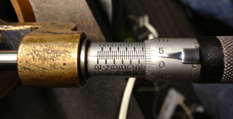
I then started to machine the liner, but I noticed that the cut was greater on one side and not removing material from the opposite side, so I decided to recenter the Whatton at the top of the liner held in the rig. This is actually the bottom of the liner in reality...
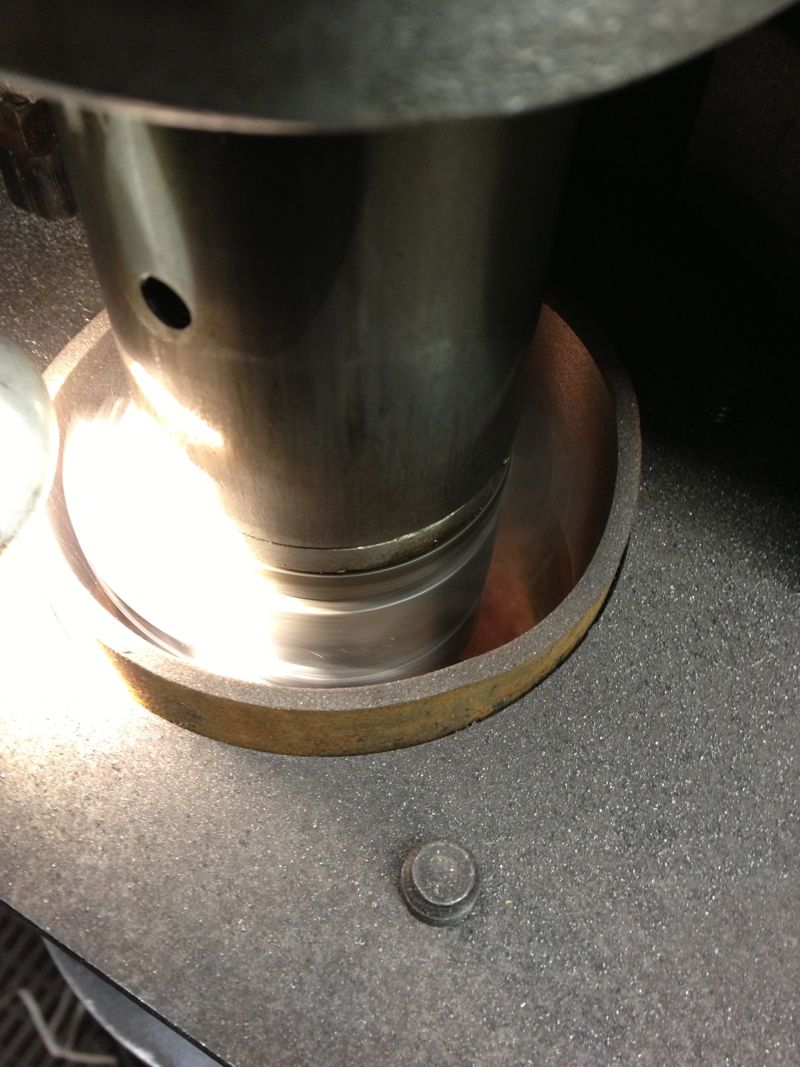
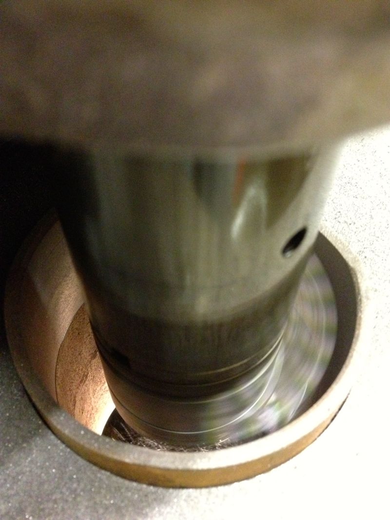
You can see the slight ring at the top in this picture above, when I centred the liner at the top of rig, and in the picture below, the area missed in the machining.
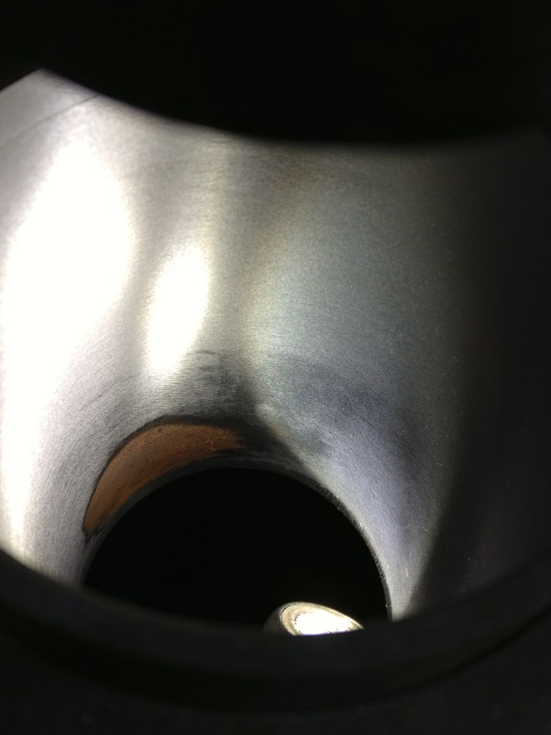
Obviously, further machining is required, but whether it will remove this blemish inside the liner is not known until you try, so it’s time to reset the cutting tip and see if cutting a slightly larger diameter will do it. New diameter is set at 3.3665”, as shown below, by sliding the tooltip out towards the micrometer.
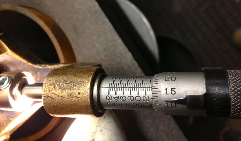
and then after tightening the tooltip locking screw, a quick recheck, but there’s not much difference here, about a thou, so it’s now reading 3.3655” as shown below.
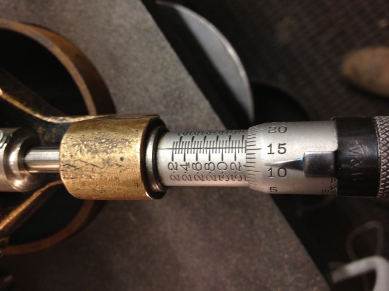
Notice how the top step is taken out by machining a larger diameter, but what will happen later on?
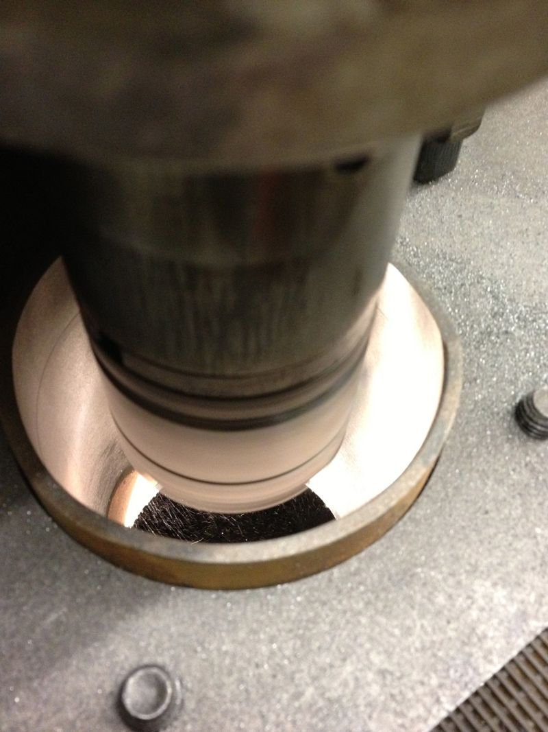
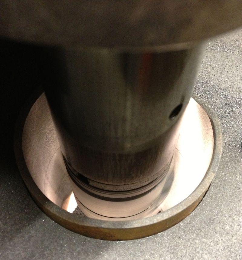
So when the second cut is finished, I let the tooltip pass through the liner & bottom mounting plate, and recheck the tooltip bore diameter, which hasn’t changed and reads 3.3655”. All is looking good.
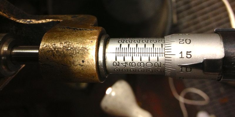
However a quick check with the Bowers imperial three point micrometer reveals the actual bore measurement is 3.3614”, so the Whatton is reading about 0.004” oversize.
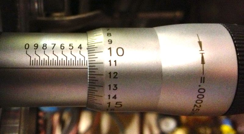
It’s still a good result, as I can now calibrate the Whatton micrometer to the actual bore size by resetting the detent. Incidentally the wear wasn’t quite machined out of the bottom part of the liner, (top in the picture below), but as it was less than 0.0005” on diameter when measured, the final cross hatch & prior honing process will remove this comfortably.
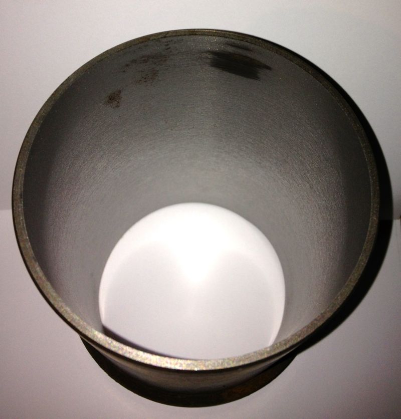
I decided to test the calibration by machining the other liner, but this time centre the Whatton with the bottom of the rig, as I originally started to do with the above liner. This left a very slight un-machined area at the top of the liner, which is really the bottom. No rings operate in this area, so it’s not critical, but either way it will be removed by the final honing process too.
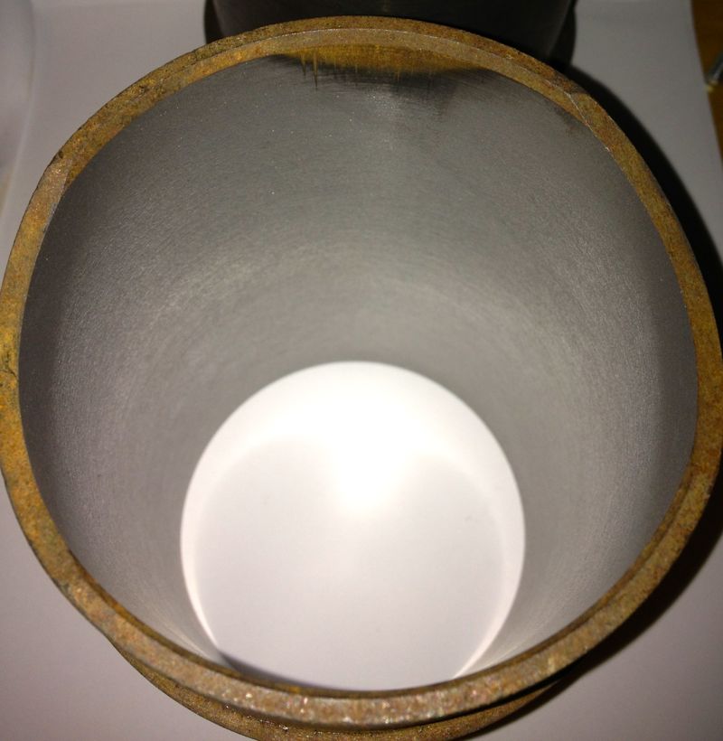
This second liner was machined at just under 3.366” using the Whatton direct reading micrometer, but after boring it measured 85.500mm with the three point Mitutoyo, and 3.3663” using the Bowers, so it’s well within my operating parameters.
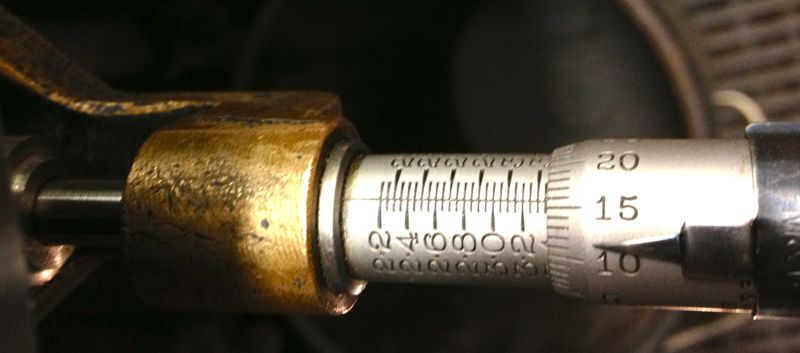
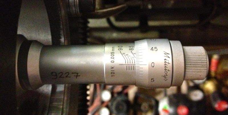
A good days work, next up, reinstall the liners, and check the finished diameters, so the true clearance can be established or continue to test hone the cylinder liners using the Delapena hone. For the latter, I will have to CAD up a drawing, as I need to make a rig to hold the liners, before I can hone them properly. It’s not worth using the Whatton set up, as it’ll be too much disruption.
I decided on an arbitrary test bore of 3.353” for the first cut, which is approximately 85.1mm, and just a bit oversize on the original liners.
I then started to machine the liner, but I noticed that the cut was greater on one side and not removing material from the opposite side, so I decided to recenter the Whatton at the top of the liner held in the rig. This is actually the bottom of the liner in reality...
You can see the slight ring at the top in this picture above, when I centred the liner at the top of rig, and in the picture below, the area missed in the machining.
Obviously, further machining is required, but whether it will remove this blemish inside the liner is not known until you try, so it’s time to reset the cutting tip and see if cutting a slightly larger diameter will do it. New diameter is set at 3.3665”, as shown below, by sliding the tooltip out towards the micrometer.
and then after tightening the tooltip locking screw, a quick recheck, but there’s not much difference here, about a thou, so it’s now reading 3.3655” as shown below.
Notice how the top step is taken out by machining a larger diameter, but what will happen later on?
So when the second cut is finished, I let the tooltip pass through the liner & bottom mounting plate, and recheck the tooltip bore diameter, which hasn’t changed and reads 3.3655”. All is looking good.
However a quick check with the Bowers imperial three point micrometer reveals the actual bore measurement is 3.3614”, so the Whatton is reading about 0.004” oversize.
It’s still a good result, as I can now calibrate the Whatton micrometer to the actual bore size by resetting the detent. Incidentally the wear wasn’t quite machined out of the bottom part of the liner, (top in the picture below), but as it was less than 0.0005” on diameter when measured, the final cross hatch & prior honing process will remove this comfortably.
I decided to test the calibration by machining the other liner, but this time centre the Whatton with the bottom of the rig, as I originally started to do with the above liner. This left a very slight un-machined area at the top of the liner, which is really the bottom. No rings operate in this area, so it’s not critical, but either way it will be removed by the final honing process too.
This second liner was machined at just under 3.366” using the Whatton direct reading micrometer, but after boring it measured 85.500mm with the three point Mitutoyo, and 3.3663” using the Bowers, so it’s well within my operating parameters.
A good days work, next up, reinstall the liners, and check the finished diameters, so the true clearance can be established or continue to test hone the cylinder liners using the Delapena hone. For the latter, I will have to CAD up a drawing, as I need to make a rig to hold the liners, before I can hone them properly. It’s not worth using the Whatton set up, as it’ll be too much disruption.
Panhard Cylinder Liner Removal
27/10/12 13:07 Filed in: Panhard Piston | Panhard Engine
As usual I have been working away, and work has been taking all my time, but today I collected some test cylinders from John Passfield. These were early Dyna ones, and I just needed the liners to machine.
First you have to get them out of the cylinders, Panhard suggests using a U shaped gas torch, but to be honest any large roofing torch, or an electric fan oven will do it. The latter is a no no if it is in the house, as the old oils etc leave a nice odour that Febreze won’t shift!
So after placing the cylinder on a lump of wood, clamped to a vice, using a large soft flame aim for the area around the finning where the nuts go onto the crankcase studs ( the metal is thickest around here), and keep moving the flame around the cylinder to spread the heat evenly.
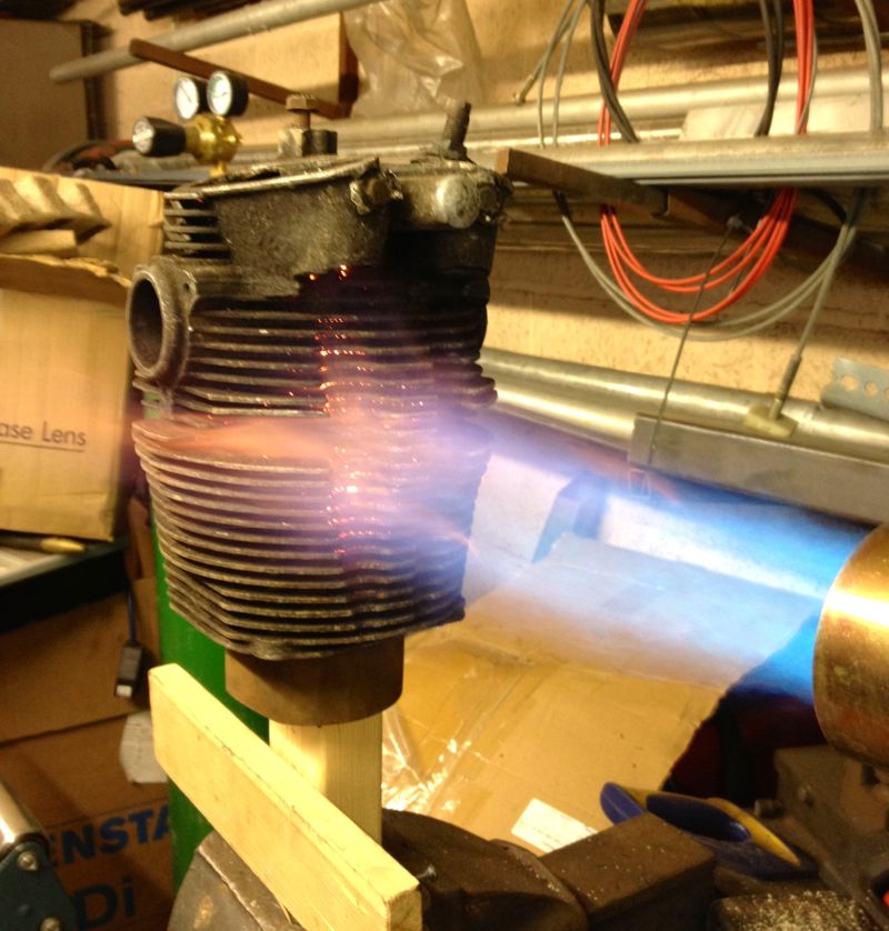
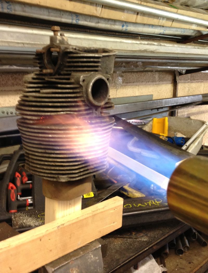
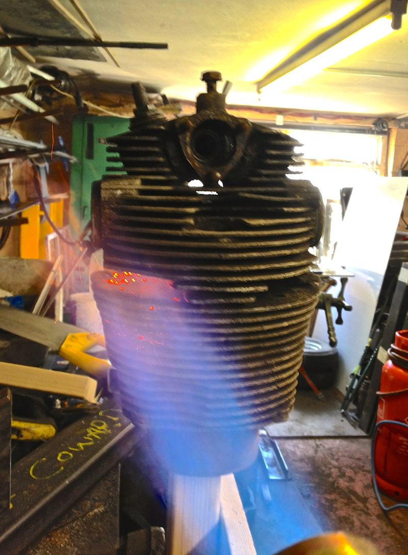
After a minute or so, the liner will drop partially and that’s why I have a piece of wood below, for it to land on. In realty it doesn’t drop to far, as the liner tends to stick to the wood, but if you tap the cylinder, it will drop clear of the aluminium cylinder.
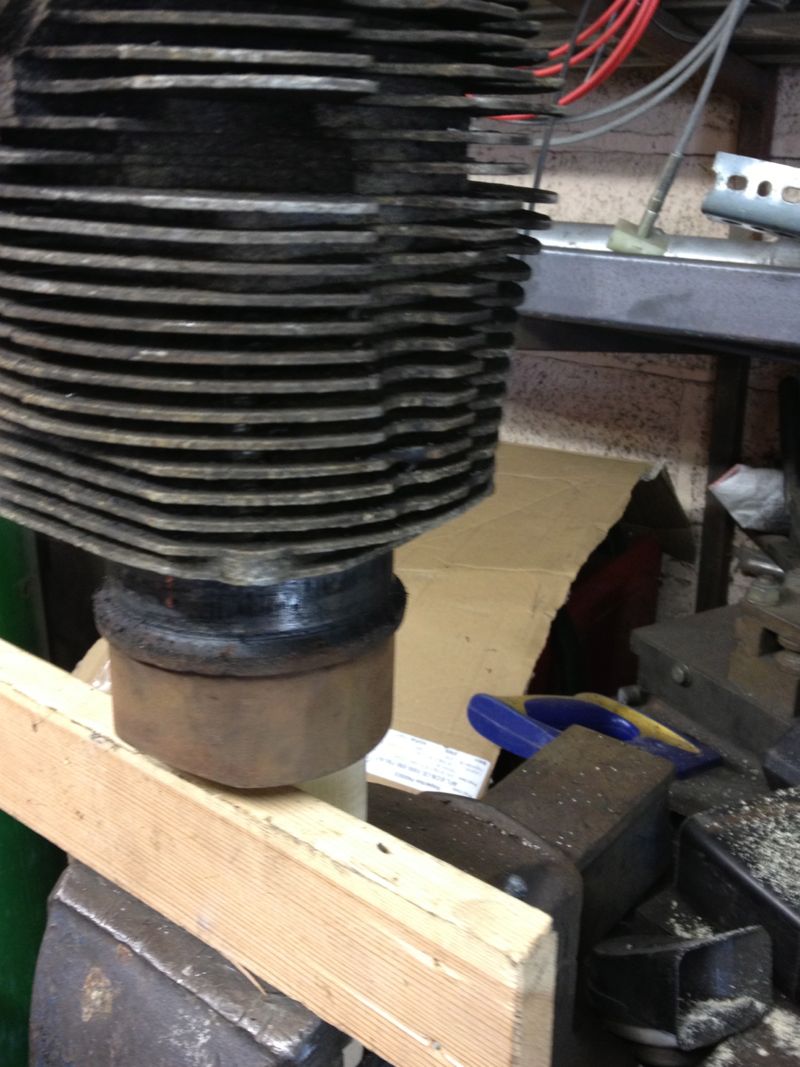
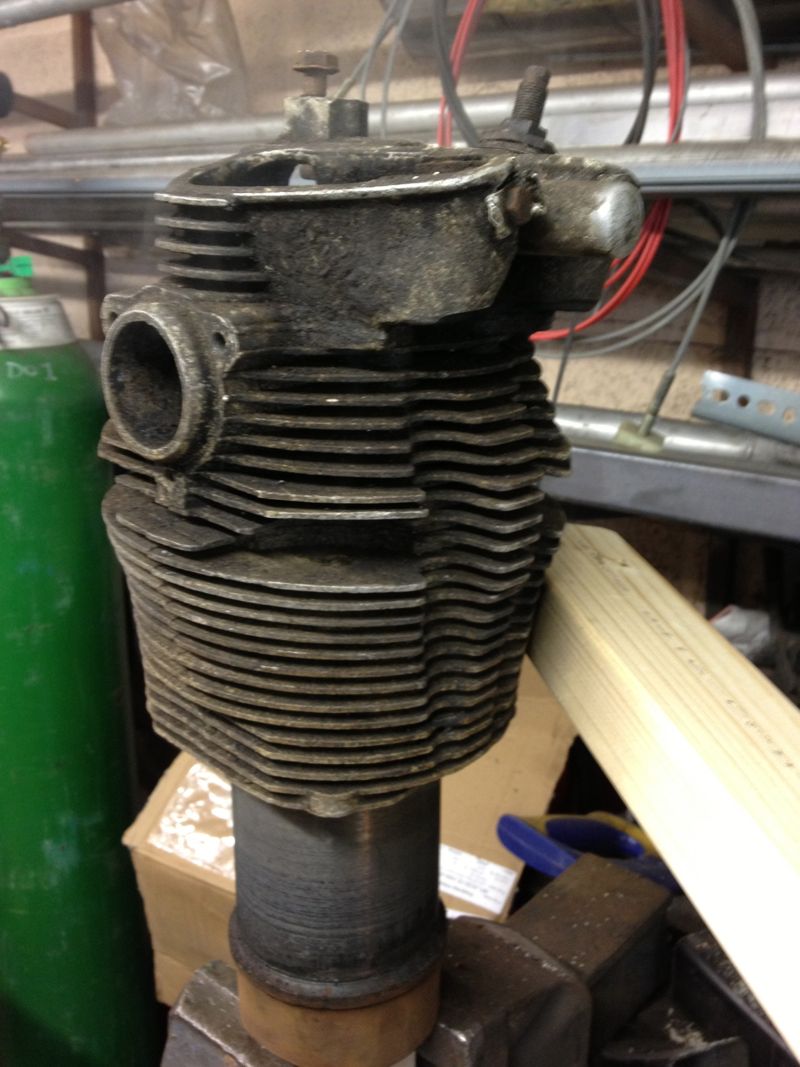
Easy really, but they will be VERY hot, so be careful and wear a heatproof glove, and let them cool naturally, which was easy today, as it was 2ºC outside.
First you have to get them out of the cylinders, Panhard suggests using a U shaped gas torch, but to be honest any large roofing torch, or an electric fan oven will do it. The latter is a no no if it is in the house, as the old oils etc leave a nice odour that Febreze won’t shift!
So after placing the cylinder on a lump of wood, clamped to a vice, using a large soft flame aim for the area around the finning where the nuts go onto the crankcase studs ( the metal is thickest around here), and keep moving the flame around the cylinder to spread the heat evenly.
After a minute or so, the liner will drop partially and that’s why I have a piece of wood below, for it to land on. In realty it doesn’t drop to far, as the liner tends to stick to the wood, but if you tap the cylinder, it will drop clear of the aluminium cylinder.
Easy really, but they will be VERY hot, so be careful and wear a heatproof glove, and let them cool naturally, which was easy today, as it was 2ºC outside.
Panhard Cylinder Liner Rebore Update 4
13/10/12 19:00 Filed in: Panhard Piston | Whatton
One of the areas I had to improve was the direct reading of the Whatton Boring Bar now that I have converted it to some readily available indexable tooltips.
The dedicated micrometer was not touching the tooltip, because the tooltip was lower than the anvil. A few moments on the lathe to test the idea, and bingo.
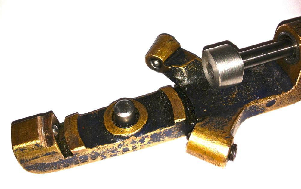
Here it is in situ, that’s attached to the anvil, with the micrometer fixed to the boring bar.
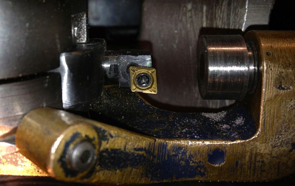
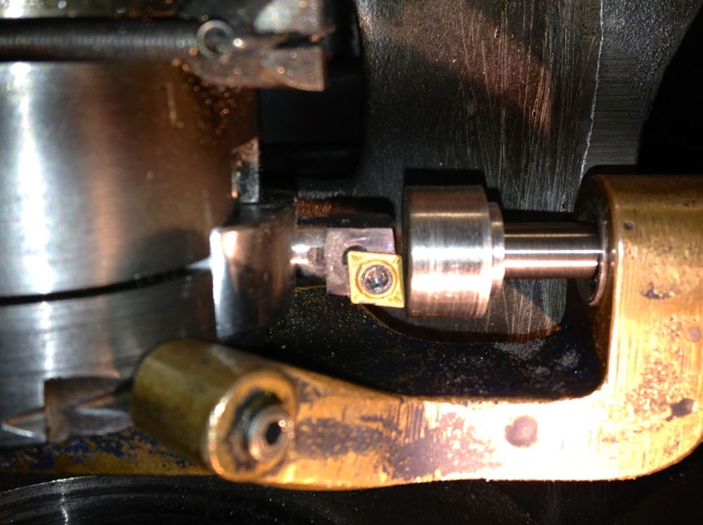
I just have to set the tip position and to do another test bore to establish the actual bore size measured by the three point bore micrometer versus the indicated reading of the Whatton micrometer.
The dedicated micrometer was not touching the tooltip, because the tooltip was lower than the anvil. A few moments on the lathe to test the idea, and bingo.
Here it is in situ, that’s attached to the anvil, with the micrometer fixed to the boring bar.
I just have to set the tip position and to do another test bore to establish the actual bore size measured by the three point bore micrometer versus the indicated reading of the Whatton micrometer.
Panhard Cylinder Liner Rebore Update 3
07/10/12 17:02 Filed in: Panhard Piston | Whatton
Yet again, I could only manage a few hours on the Panhard stuff, but I have finally cured the machining issues I had reboring the liners.
This is the set up as it stands now, long tooltip holder, modified LH boring bar with indexable CCMT insert, but unfortunately the longer tooltip holder fouls the boring bar micrometer body, so I cannot take a direct measurement using it at the moment. A little tweak with a Dremel should solve this, but I’ll do it another day, when I make a sleeve for the anvil, so it contacts the lower cutting surface of the new indexable insert.
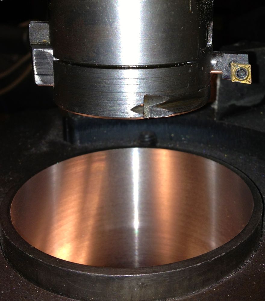
On examination the bore was truly round, had a good consistent surface finish and measured 86.03 mm at the top, middle and bottom. I have eliminated the chatter that caused the rippling to the bore last weekend, by using the larger tooltip holder, but I got a slight scoring at three points afterwards. However, a slower feed speed, as well as tightening the spring loaded gibs, and increasing the pressure on the boring bar sleeves to eliminate the sliding play stopped any further occurrences.
Interestingly the original induction motor runs lot cooler with the vacuum pump motor coupling, which has a rubber cush drive rather than a leather or felt pad, and even with the increased loadings and therefore additional effort required to move the boring bar ,through the slides, there is no increase in temperature.
The ripple to the bores was caused by me inadvertently using the shorter tooltip holder, which is really made for the smaller bores sizes. The grub screw which is designed to lock the tooltip holder in position, was in fact gripping the adjusting plate, and so the tooltip holder was vibrating and moving on the screw adjuster.
Considering I didn’t have a manual, or know of any other person with one of these, losing just one liner to teething issues is a good result.
Here is the test cylinder after honing, but not washed yet though.
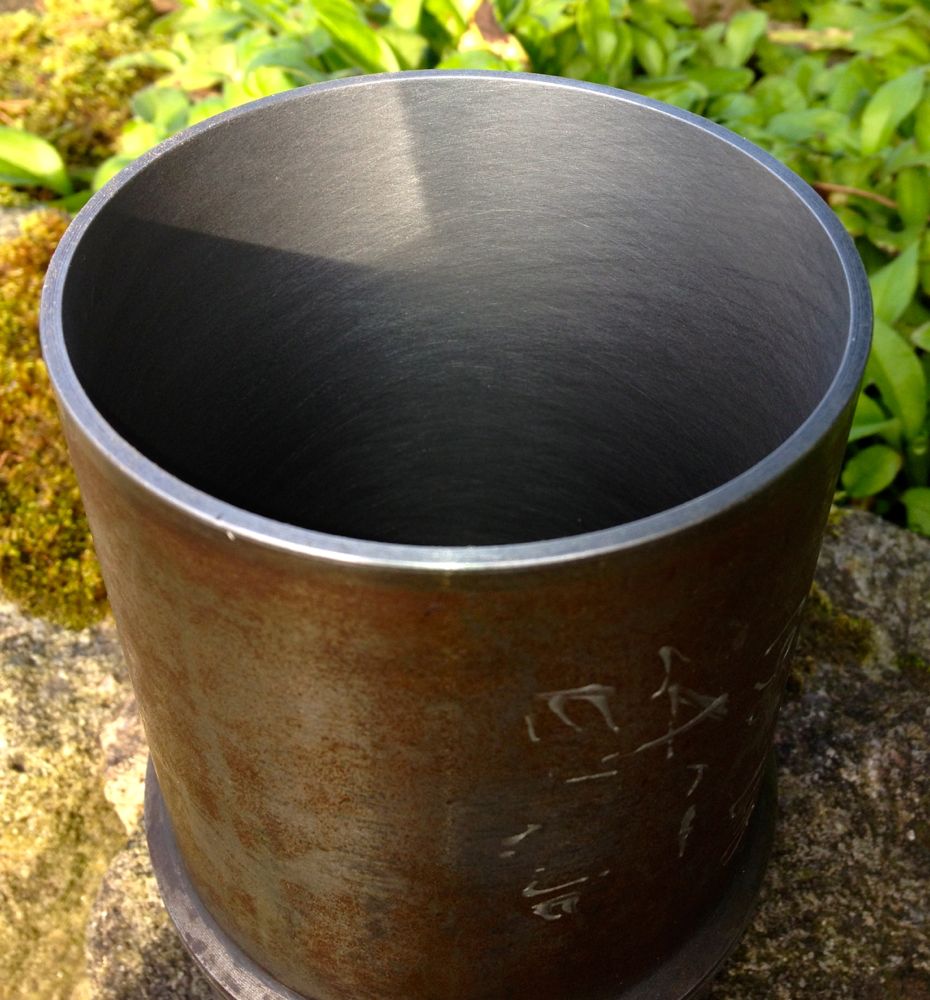
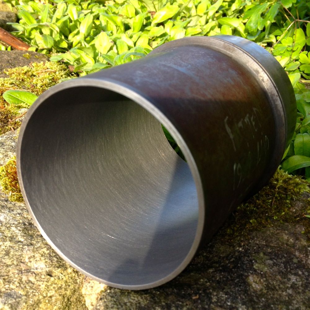
This is the set up as it stands now, long tooltip holder, modified LH boring bar with indexable CCMT insert, but unfortunately the longer tooltip holder fouls the boring bar micrometer body, so I cannot take a direct measurement using it at the moment. A little tweak with a Dremel should solve this, but I’ll do it another day, when I make a sleeve for the anvil, so it contacts the lower cutting surface of the new indexable insert.
On examination the bore was truly round, had a good consistent surface finish and measured 86.03 mm at the top, middle and bottom. I have eliminated the chatter that caused the rippling to the bore last weekend, by using the larger tooltip holder, but I got a slight scoring at three points afterwards. However, a slower feed speed, as well as tightening the spring loaded gibs, and increasing the pressure on the boring bar sleeves to eliminate the sliding play stopped any further occurrences.
Interestingly the original induction motor runs lot cooler with the vacuum pump motor coupling, which has a rubber cush drive rather than a leather or felt pad, and even with the increased loadings and therefore additional effort required to move the boring bar ,through the slides, there is no increase in temperature.
The ripple to the bores was caused by me inadvertently using the shorter tooltip holder, which is really made for the smaller bores sizes. The grub screw which is designed to lock the tooltip holder in position, was in fact gripping the adjusting plate, and so the tooltip holder was vibrating and moving on the screw adjuster.
Considering I didn’t have a manual, or know of any other person with one of these, losing just one liner to teething issues is a good result.
Here is the test cylinder after honing, but not washed yet though.
Panhard Cylinder Liner Rebore Update 2
29/09/12 20:09 Filed in: Panhard Piston | Whatton
Today I collected the tooltips that I had modified, and also fitted the vee belts, that had arrived in the post earlier in the week, to the Whatton Boring Bar. After struggling to get them onto the pulleys, and replacing the top cover, I fitted a new indexable tips to the short tool tip holder.
I centralised the bar over the liner and went to adjust the tip using the micrometer, and discovered the tooltip was not catching the micrometer anvil, because it cuts slightly lower now it misses the anvil tip. I will have to make a larger diameter adaptor to sleeve & cap over the anvil of the micrometer, which might add say 0.1” thick overall externally, to make reading the actual size easier. A bit of machined silvered steel to the rescue, aided by a helpful chap on a tool grinder down the road.
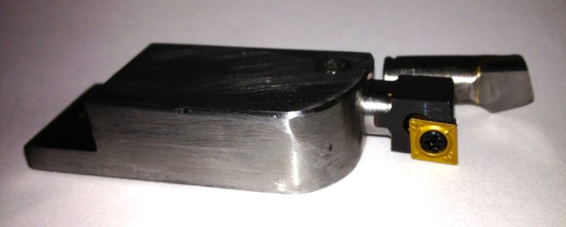
If you look at the picture above you can see the cutting edge is much lower than the centre line of the old carbide tip.
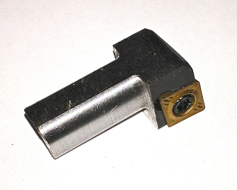
This is the 12mm square shank tool converted in the long holder with a 8mm square shanked version in the background. The original tip is in the foreground.
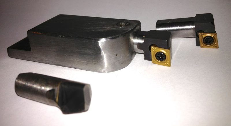
I started to machine the liner, and the motor never stalled at all, so finally a little success, and the first shallow cut was of a very good surface finish. Next I tried a slower roughing cut, and after about halfway down the liner, some strange swishing/grating noises started to reverberate from the bar. I couldn’t see what was happening, as the heavier cut was creating a fair amount of dust, (note to me, need a vacuum source to remove cutting dust). When I looked at the bore after the cutting process had finished, I had a perfect bore for about half the length of the liner, then a series of ridges or ringed undulations. :eek
I had to leave off at that point and sort out a few other jobs, but it would appear the back edge of the tooltip was catching the bore, which is easily remedied by grinding an increased taper behind the tooltip face, but more importantly & slightly worrying is the only way it could ring the bore was if the tooltip was moving. I am going to try with the longer tooltip holder to see if the short tool holder was rocking slightly, and therefore pushing into the liner. I will also double check the gigs that take up the play on the bar as it travels downwards. The latter wasn’t an issue before, but I have to check.
Anyway I am pleased that the motor/tooltip stall with the original carbide tipped tools isn’t repeating itself, just got to work on this new problem.
I centralised the bar over the liner and went to adjust the tip using the micrometer, and discovered the tooltip was not catching the micrometer anvil, because it cuts slightly lower now it misses the anvil tip. I will have to make a larger diameter adaptor to sleeve & cap over the anvil of the micrometer, which might add say 0.1” thick overall externally, to make reading the actual size easier. A bit of machined silvered steel to the rescue, aided by a helpful chap on a tool grinder down the road.
If you look at the picture above you can see the cutting edge is much lower than the centre line of the old carbide tip.
This is the 12mm square shank tool converted in the long holder with a 8mm square shanked version in the background. The original tip is in the foreground.
I started to machine the liner, and the motor never stalled at all, so finally a little success, and the first shallow cut was of a very good surface finish. Next I tried a slower roughing cut, and after about halfway down the liner, some strange swishing/grating noises started to reverberate from the bar. I couldn’t see what was happening, as the heavier cut was creating a fair amount of dust, (note to me, need a vacuum source to remove cutting dust). When I looked at the bore after the cutting process had finished, I had a perfect bore for about half the length of the liner, then a series of ridges or ringed undulations. :eek
I had to leave off at that point and sort out a few other jobs, but it would appear the back edge of the tooltip was catching the bore, which is easily remedied by grinding an increased taper behind the tooltip face, but more importantly & slightly worrying is the only way it could ring the bore was if the tooltip was moving. I am going to try with the longer tooltip holder to see if the short tool holder was rocking slightly, and therefore pushing into the liner. I will also double check the gigs that take up the play on the bar as it travels downwards. The latter wasn’t an issue before, but I have to check.
Anyway I am pleased that the motor/tooltip stall with the original carbide tipped tools isn’t repeating itself, just got to work on this new problem.
Panhard Cylinder Liner Rebore Update 1
23/09/12 14:18 Filed in: Panhard Piston | Whatton
I recently bought an upgraded version of the original motor off eBay, a 370W or 1/2 horsepower with the correct baseplate. However when I tried to swap the motor over today, I discovered the increased height or length didn’t allow it to clear the main casting. I had to revert back to the old motor, but I did use the cush drive off the vacuum pump, which was more concentric than the old part, and the boring machine is much quieter, with less vibration.
I have been doing all the attempted cuts so far with a single belt, and really struggled to fit one belt let alone the two that are required. Today I managed to fit the sister belt, a Z16 428 Ld, 410 Li onto the double fee pulley. It was at this point I notice the other belt was slightly stretched and greasy. The frayed edges are a result of a woodruff key being fitted incorrectly by the previous owner, it should never had one, as it had a hardened circular pin, that located in a vertical keyway. The woodruff key grabbed and wore itself out, and caused the belt to run at an angle, so cutting the edges.
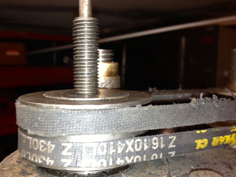
I cannot guarantee I will get the same, so I have ordered two new belts to replace the stretched one. I also have a novel way (new to me) of getting the vee belt onto the pulleys, which doesn’t involve taking the pulleys off and sliding them down the shafts, however I cannot tell you how, as it might mean a silly person could lose a finger. Suffice to say, I cannot turn the pulleys by hand to get the belt to fall into its respective groove without it needing some electrical assistance.
The tooltips were scheduled to be done today, but I am pleased they haven’t been done yet as I have bought another LH boring tool to convert, and so I don’t have to pay for another set up charge.
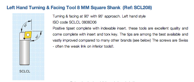
It’s 8mm square shanked, indexable and takes CCMT inserts, but I am having it shortened and made 5/16” round with a flat put on it to lock it off square in the boring head tooltip carrier.
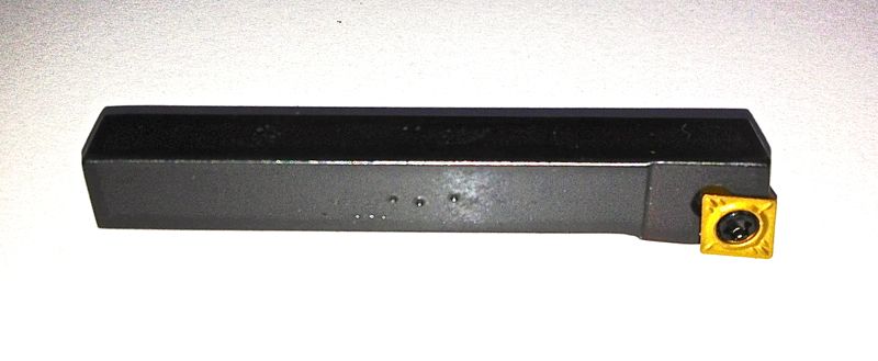
Hopefully, I will be able to use them soon, within the first week of October, in the boring machine, and then get the test liner analysed for surface finish, squareness etc at the local engineering works. If all works out, I will be able to rebore Panhard liners in the future to very precise standards.
I have been doing all the attempted cuts so far with a single belt, and really struggled to fit one belt let alone the two that are required. Today I managed to fit the sister belt, a Z16 428 Ld, 410 Li onto the double fee pulley. It was at this point I notice the other belt was slightly stretched and greasy. The frayed edges are a result of a woodruff key being fitted incorrectly by the previous owner, it should never had one, as it had a hardened circular pin, that located in a vertical keyway. The woodruff key grabbed and wore itself out, and caused the belt to run at an angle, so cutting the edges.
I cannot guarantee I will get the same, so I have ordered two new belts to replace the stretched one. I also have a novel way (new to me) of getting the vee belt onto the pulleys, which doesn’t involve taking the pulleys off and sliding them down the shafts, however I cannot tell you how, as it might mean a silly person could lose a finger. Suffice to say, I cannot turn the pulleys by hand to get the belt to fall into its respective groove without it needing some electrical assistance.
The tooltips were scheduled to be done today, but I am pleased they haven’t been done yet as I have bought another LH boring tool to convert, and so I don’t have to pay for another set up charge.
It’s 8mm square shanked, indexable and takes CCMT inserts, but I am having it shortened and made 5/16” round with a flat put on it to lock it off square in the boring head tooltip carrier.
Hopefully, I will be able to use them soon, within the first week of October, in the boring machine, and then get the test liner analysed for surface finish, squareness etc at the local engineering works. If all works out, I will be able to rebore Panhard liners in the future to very precise standards.
Panhard Cylinder Liner Rebore Test
06/08/12 23:00 Filed in: Panhard Piston | Whatton
Finally managed to machine the support plate for the cylinder liner to the right size. The lathe wasn’t able to do it, so I used the Whatton boring machine. Unfortunately, the Whatton really struggled with the work hardened laser cut plate, and the tooltips got hammered, but finally it was done.
The cylinder liner can now be held in situ, whilst it’s being rebored.
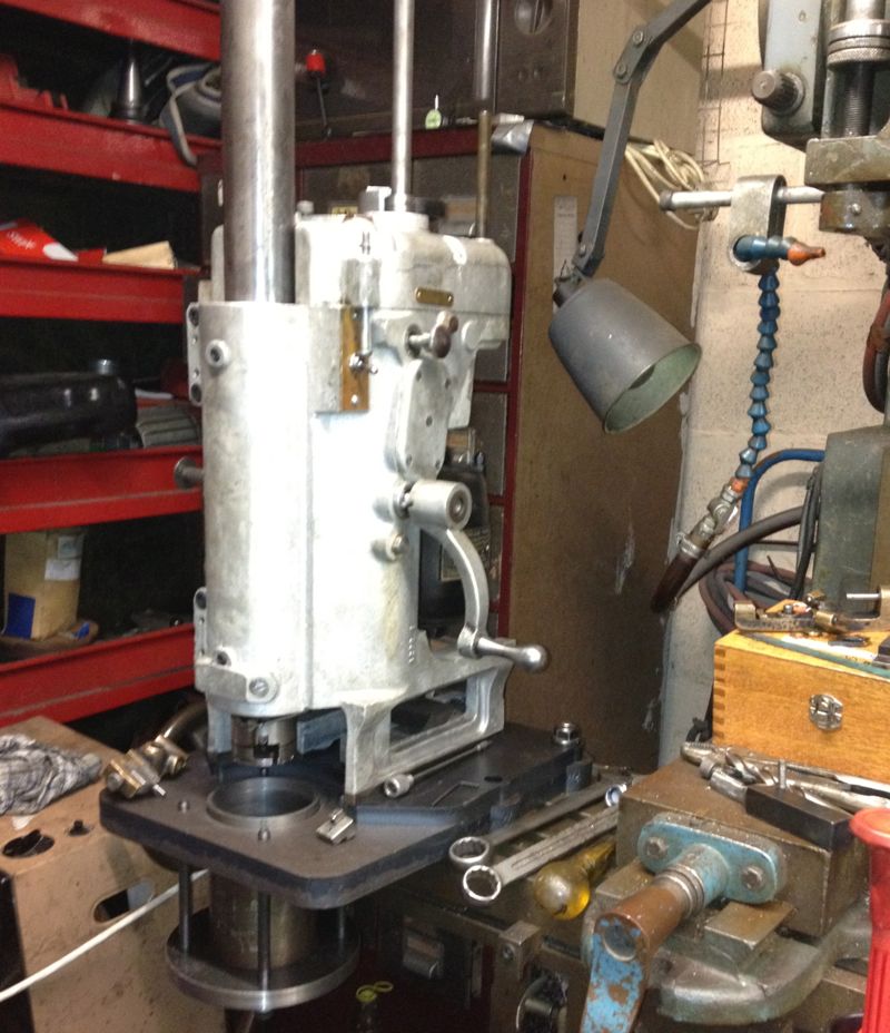
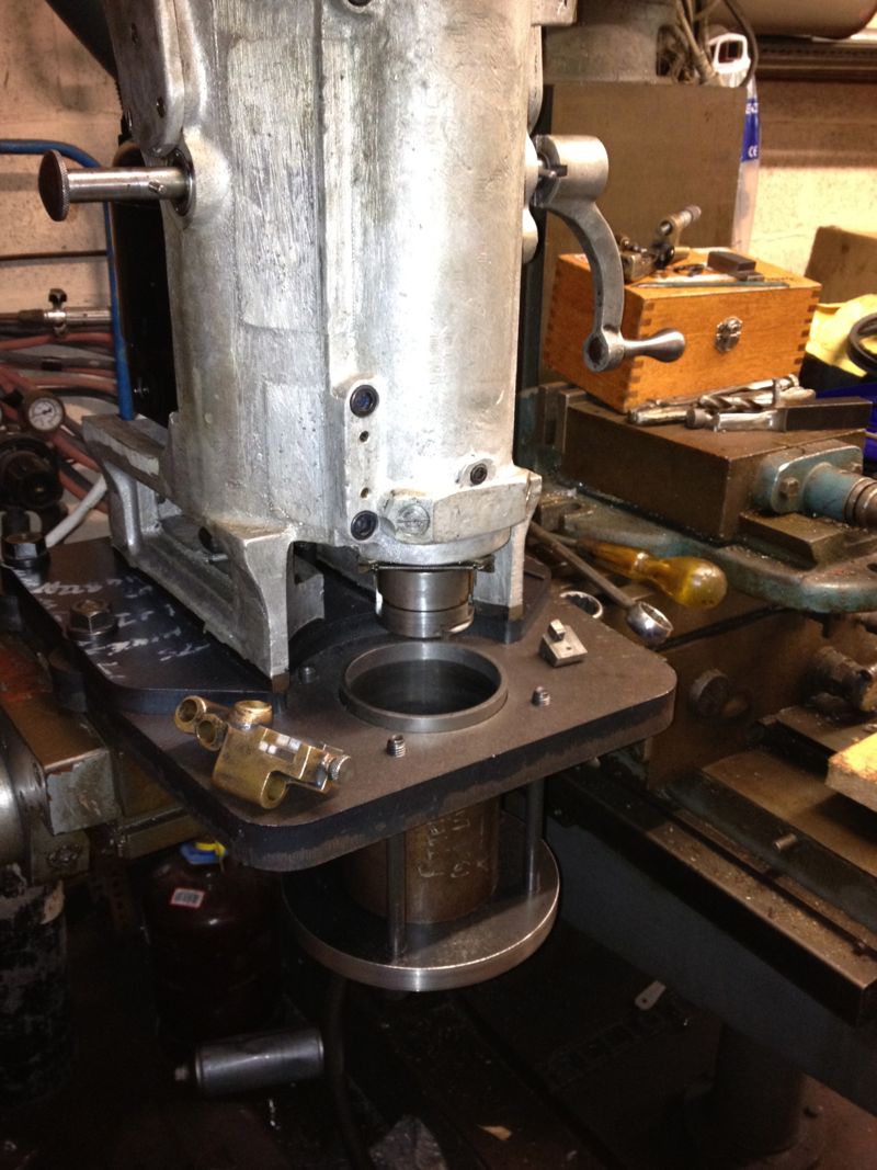
Everything is almost working OK, but I need to refine the belt tension, and the tooltip selection. I think I need to convert the Whatton to indexable tooling, as well as look at the pulley & V belt some more, as the tooltip can stall in the bore with a heavier cut.
The cylinder liner can now be held in situ, whilst it’s being rebored.
Everything is almost working OK, but I need to refine the belt tension, and the tooltip selection. I think I need to convert the Whatton to indexable tooling, as well as look at the pulley & V belt some more, as the tooltip can stall in the bore with a heavier cut.
