Panhard Piston
Panhard Cylinder Liner Rebore Update 8
03/11/12 15:39
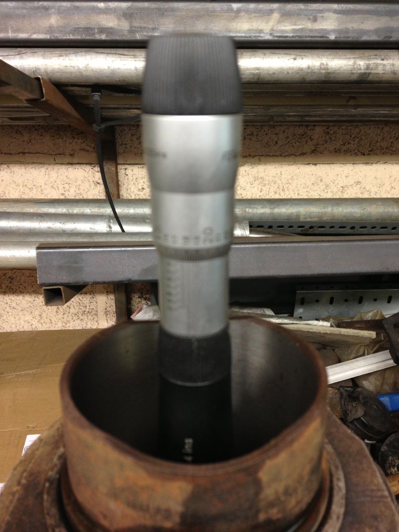
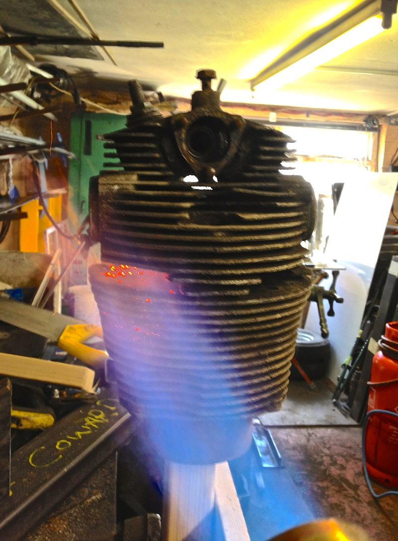
I was dropping something off at the workshop, and so I thought I’d look at the cylinder bore sizing with respect to temperature.
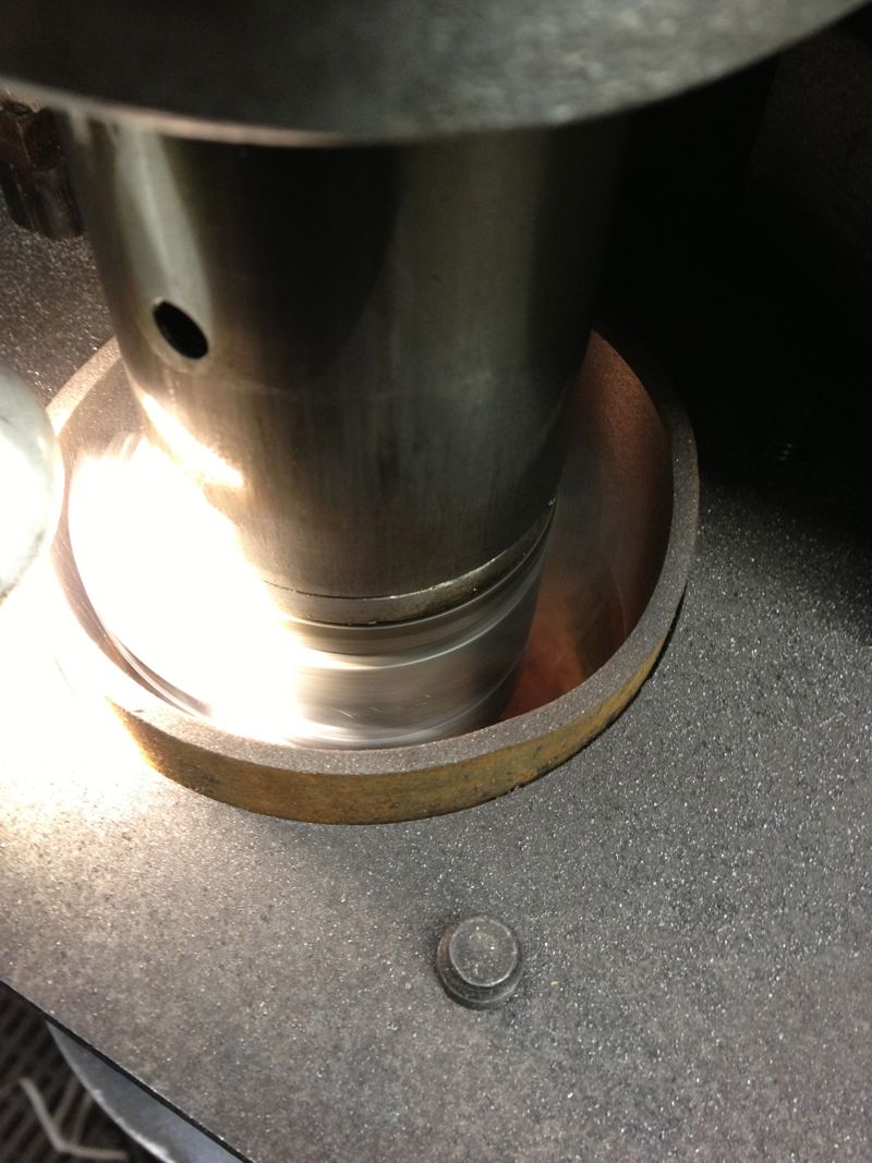
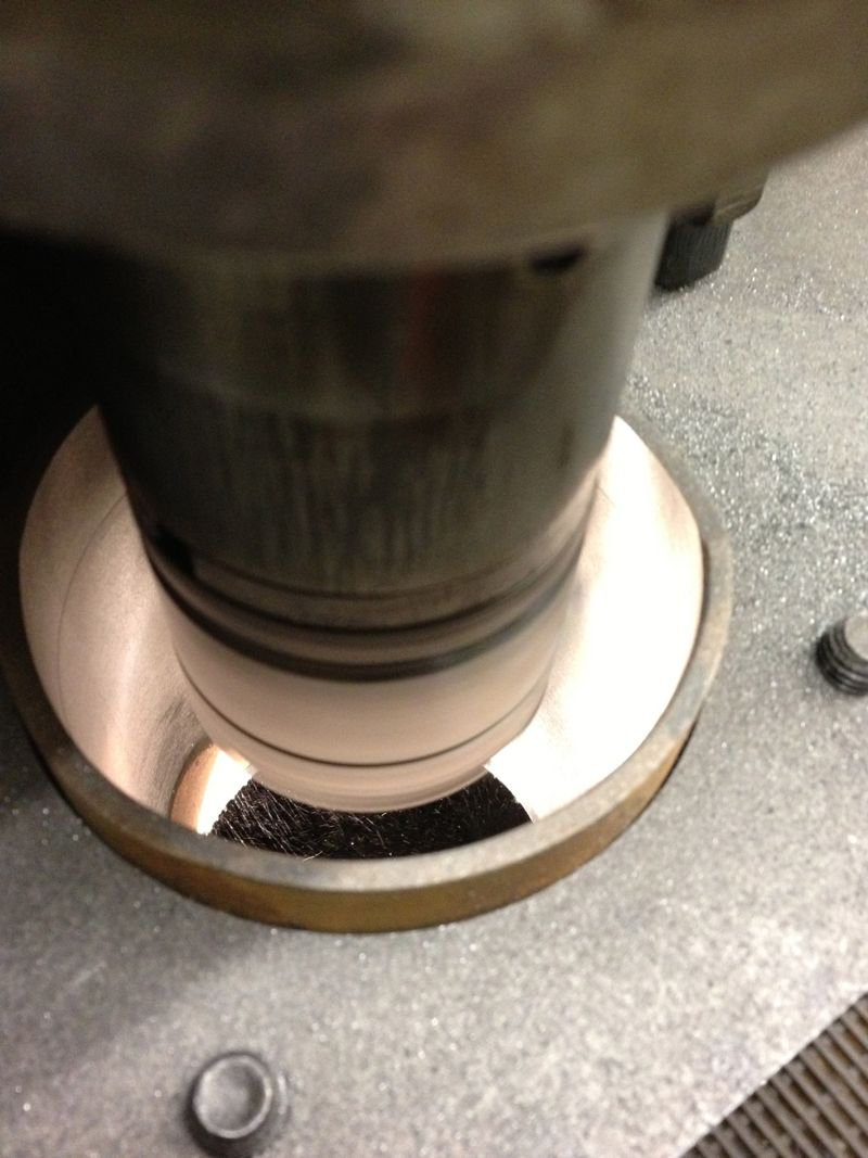
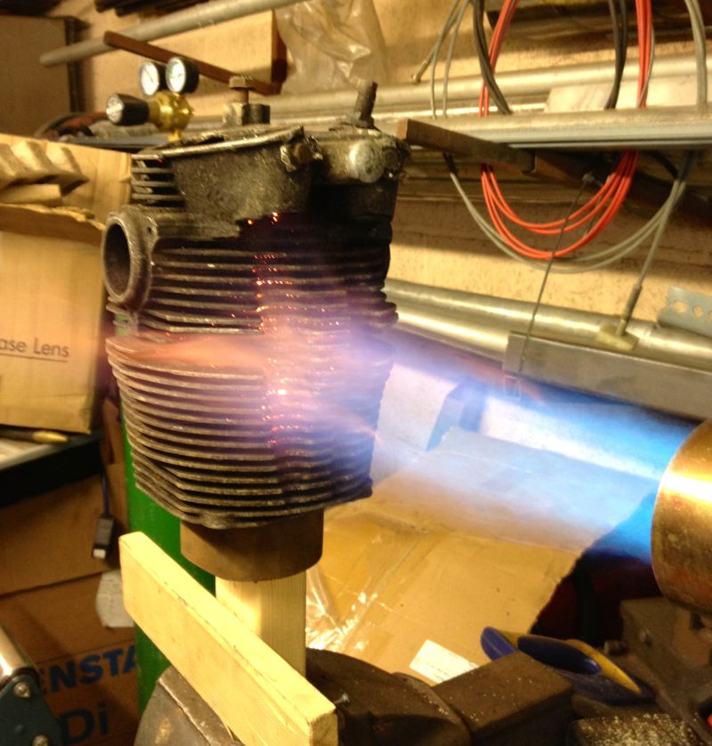
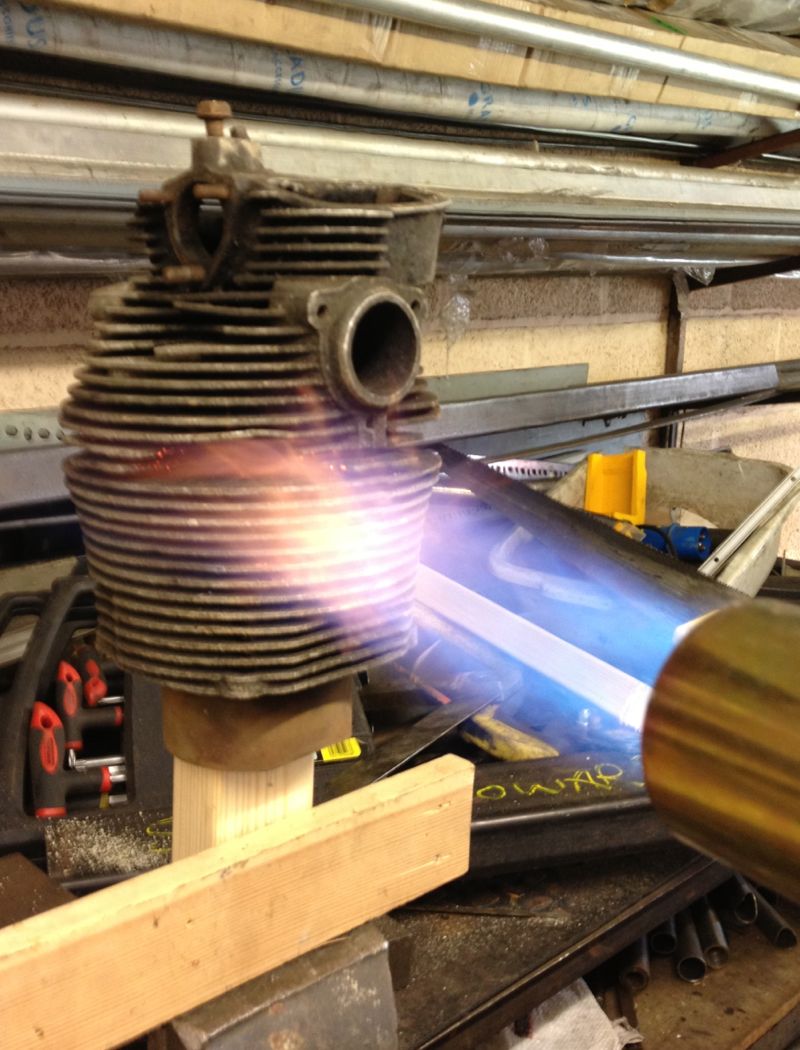
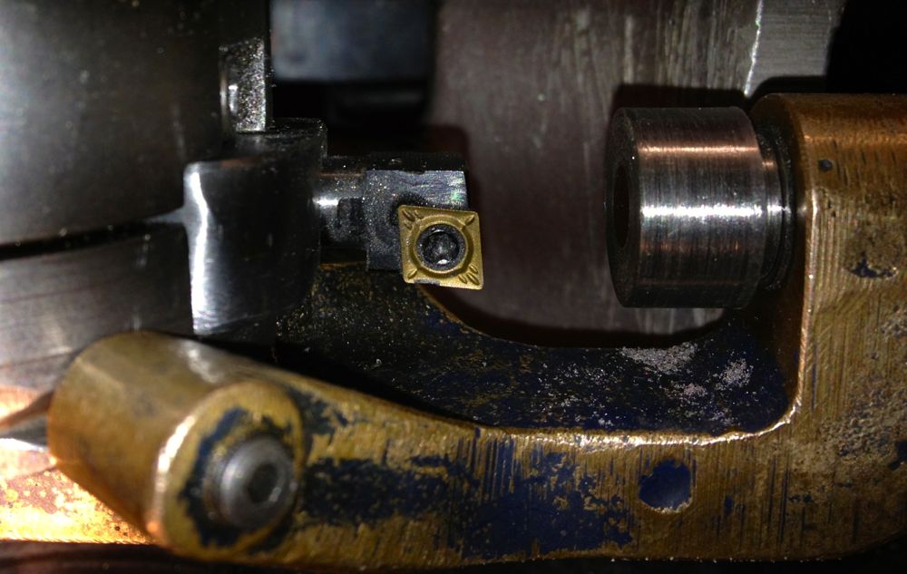
I wanted a rough idea, as too how much the cylinder would grow, and at what temperature could I expect the tapered bore to become parallel. I devised a really simple experiment, using a soft flame large propane torch ( no time for an oil bath etc), an infra red thermometer, and a three point micrometer, I quickly took snapshots of the sizes I was seeing on the micrometer, as I increased the temperature.
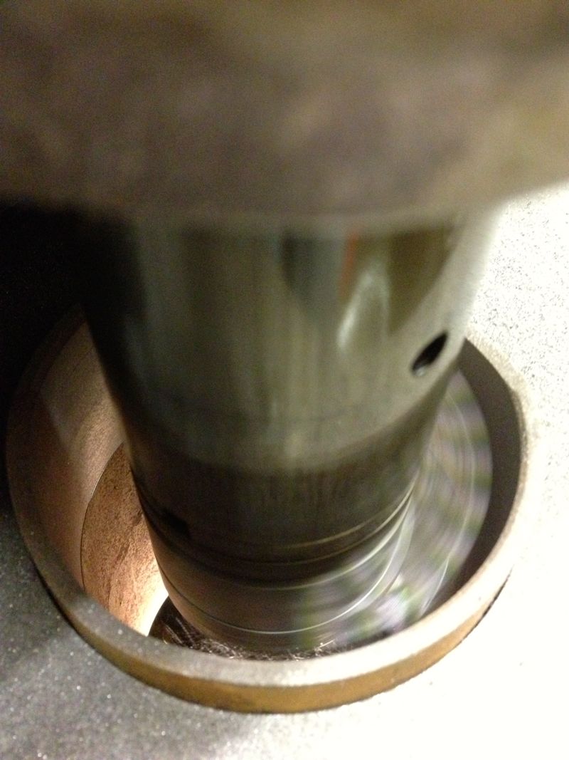
The idea was I’d measure the liner cold (today 5ºC), then about 50ºC, 100ºC and finally about 120ºC. These were just ball park figures, and the blow torch would be aimed around the cylinder finning roughly at the combustion chamber position. The temperatures were taken on the same spot, a nice black area, and the twin laser beams were focussed on this consistently. The cylinder was warmed past the temperature required and then allowed to drop to reach the desired test temperature. This way the heat would be soaking into the components more consistently.
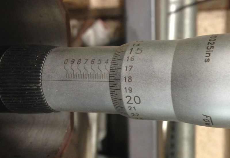
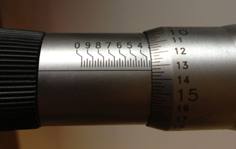
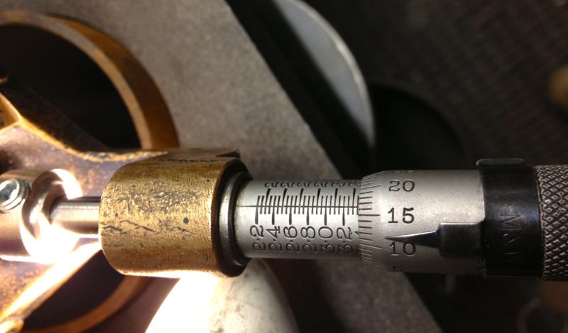
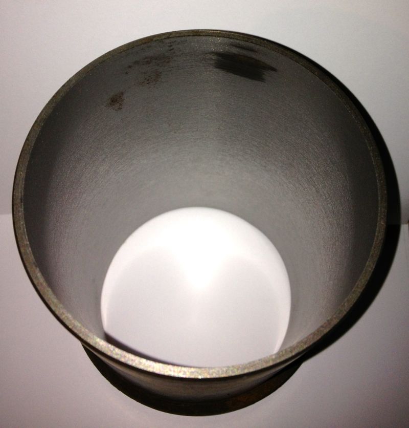
As it was a little warmer, than yesterday, the cold bore at the top of the liner measured
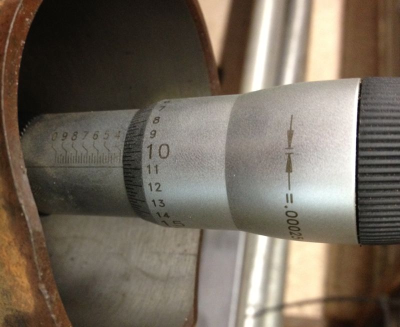
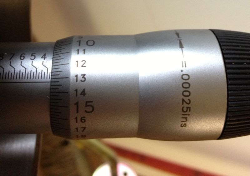
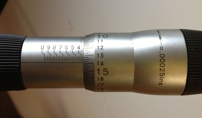
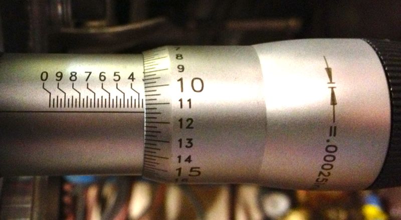
Next the cylinder was warmed up to just over 50ºC, and new readings taken, but each time I rested the micrometer in the setting ring to dissipate any heat build up caused by taking the reading. the reading shows the new top bore size, around 0.0025” larger on just 50ºC.
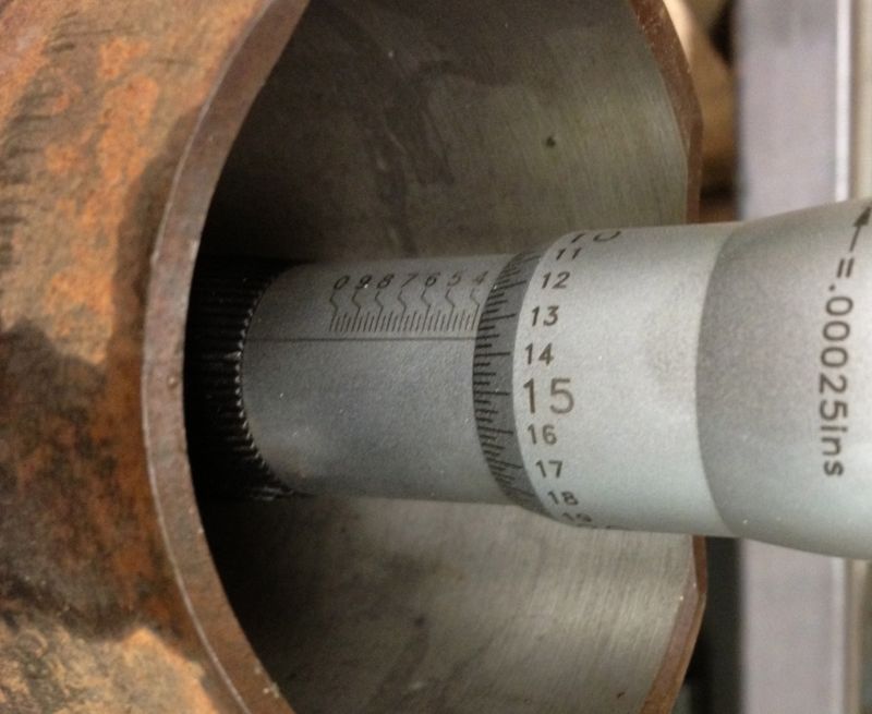
The bit just a bit further down was measured at about 0.0035” larger.
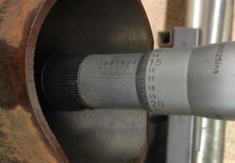
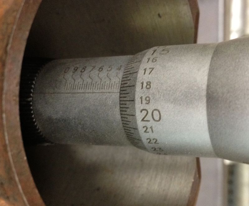
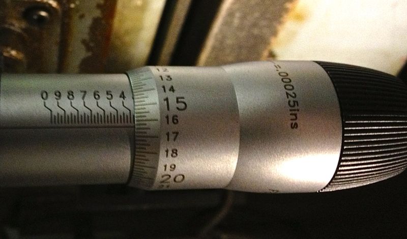
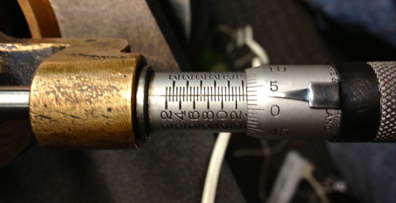
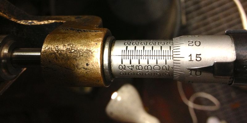
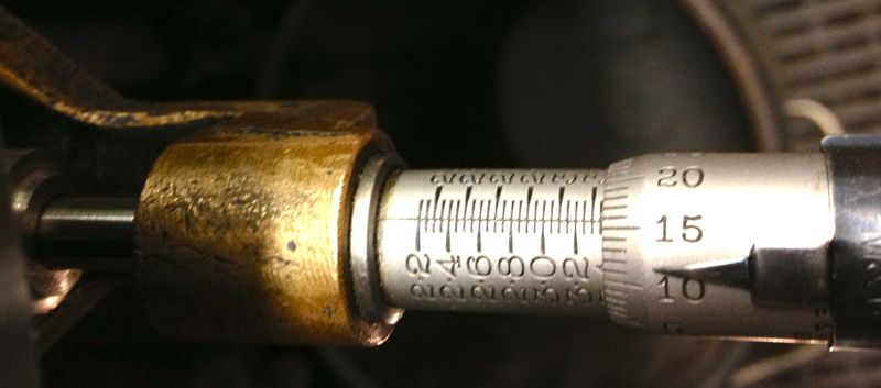
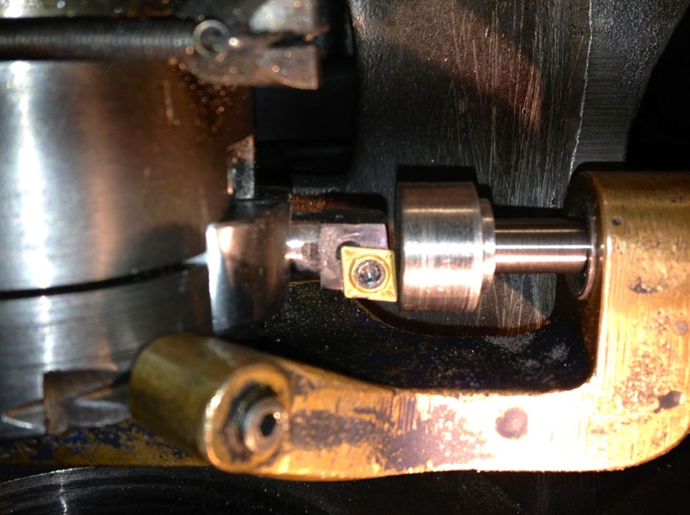
So then the cylinder was heated to just over 100ºC, and more measurements taken, and the top of the liner was reading about “16” now( another 2.5 thou larger). The middle of the liner had opened up further too, and even more lower down, as shown below
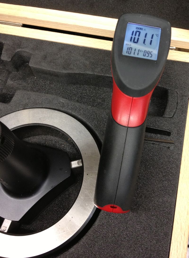
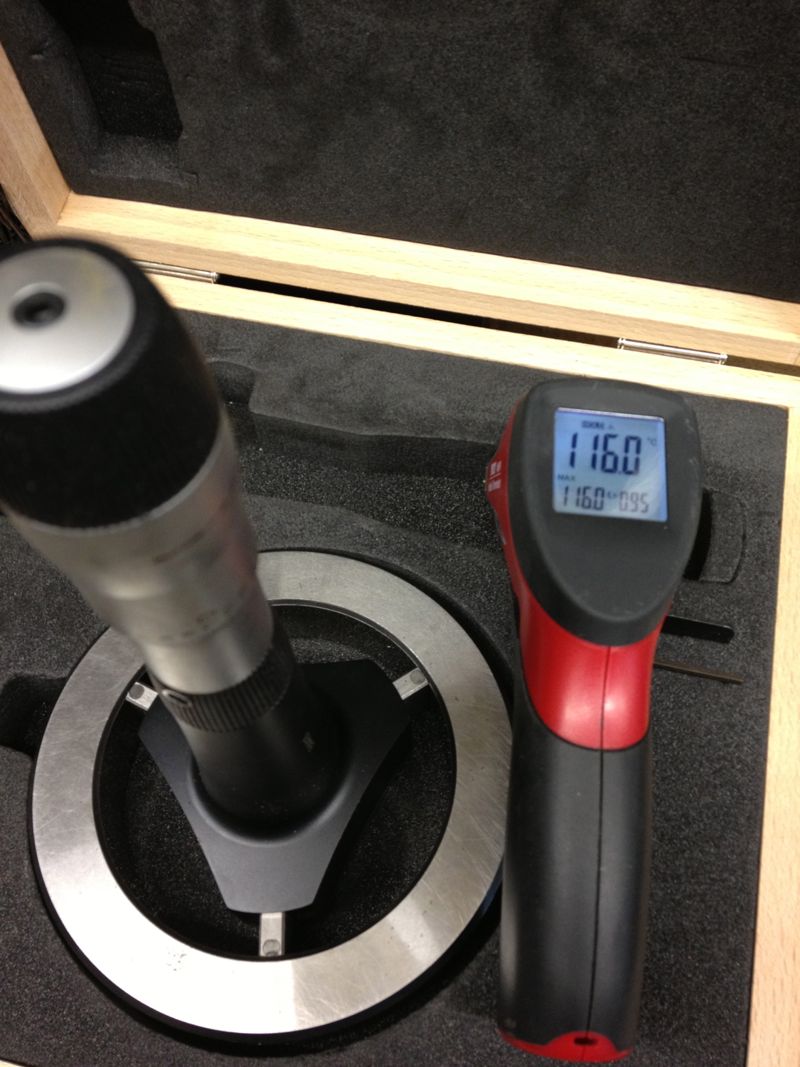
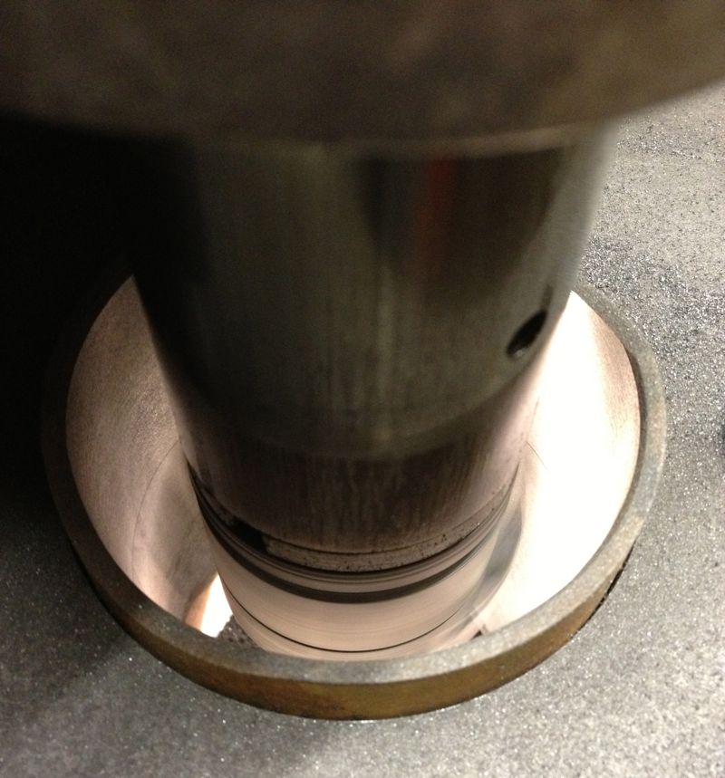
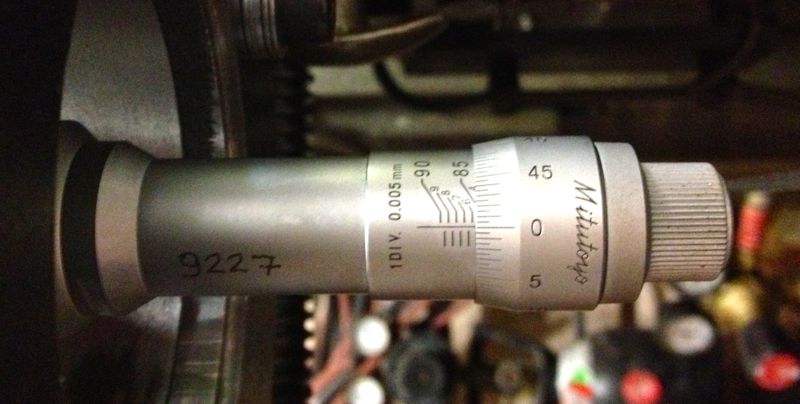
Picture below showing the setting ring and temperature at the moment of measuring.
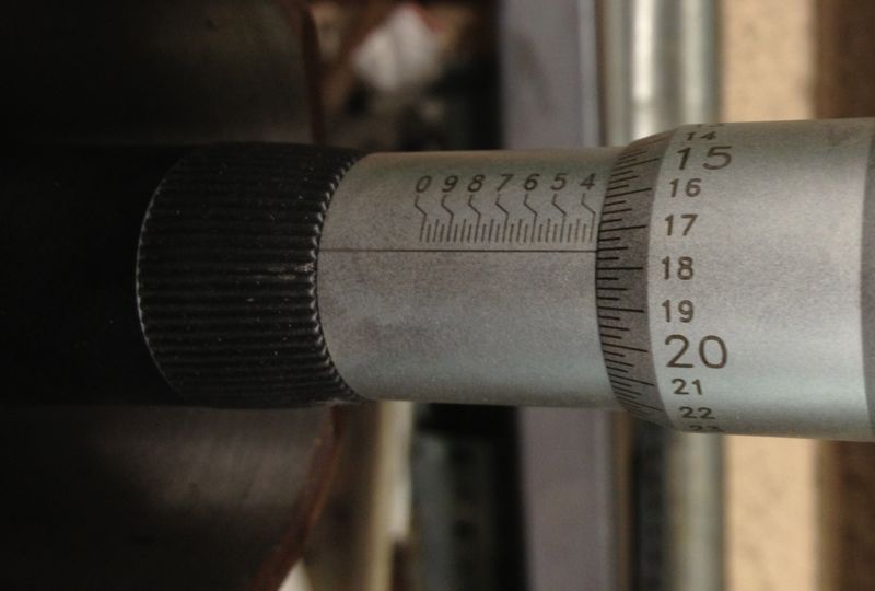
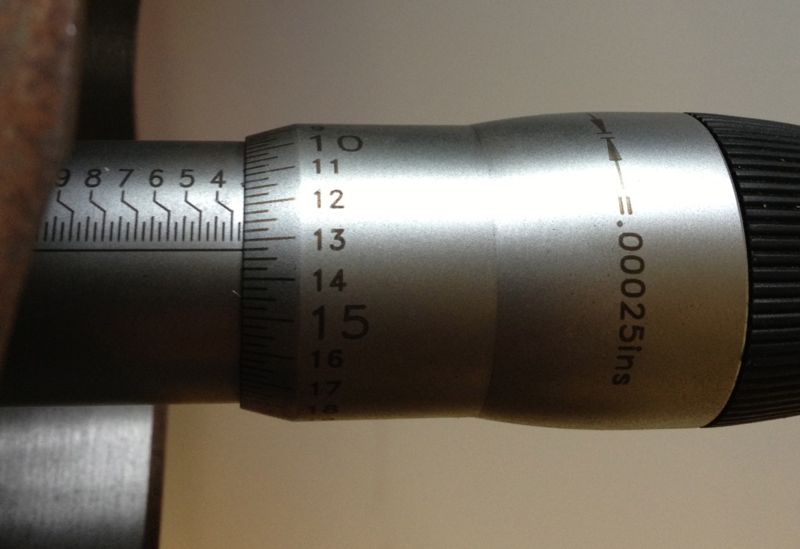
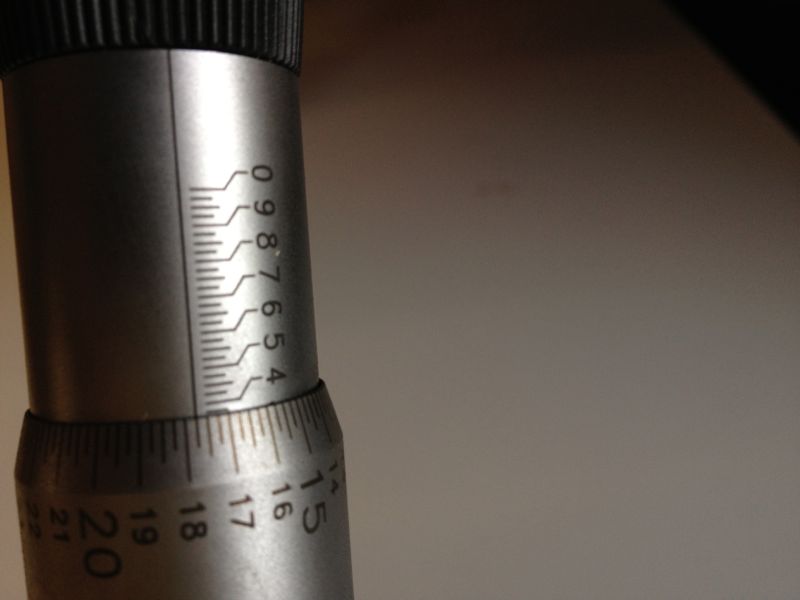
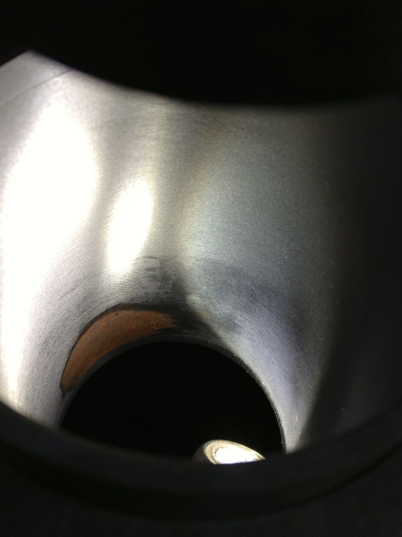
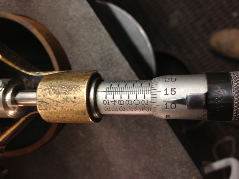
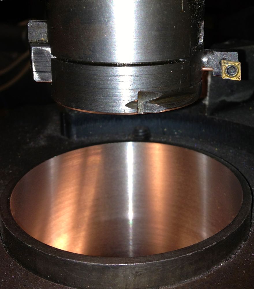
Then I heated the cylinder to about 130ºC, and let it cool slightly, and also took more measurements at the following temperature (116ºC) and then I noticed this!
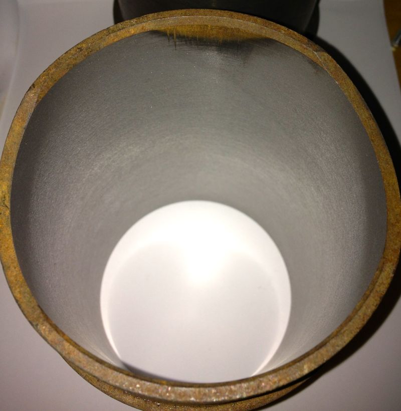
Top of liner closest to the combustion chamber measured “18” the same as the middle of the liner and the base of the liner was nearly the same, as the two images show.
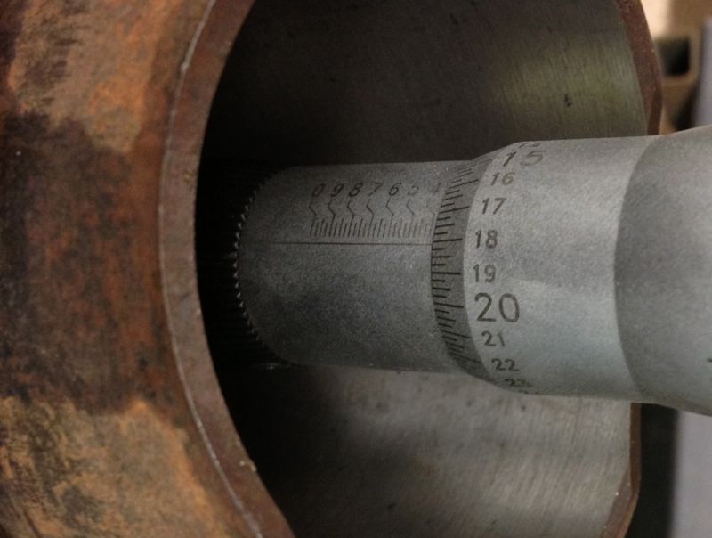
Middle measurement was blurred, but you can see it is on the “18” mark
Conclusion, at around 120ºC the cylinder casting expands enough to become parallel, so now I have a figure I can work from to set my piston clearances too.
I wanted a rough idea, as too how much the cylinder would grow, and at what temperature could I expect the tapered bore to become parallel. I devised a really simple experiment, using a soft flame large propane torch ( no time for an oil bath etc), an infra red thermometer, and a three point micrometer, I quickly took snapshots of the sizes I was seeing on the micrometer, as I increased the temperature.
The idea was I’d measure the liner cold (today 5ºC), then about 50ºC, 100ºC and finally about 120ºC. These were just ball park figures, and the blow torch would be aimed around the cylinder finning roughly at the combustion chamber position. The temperatures were taken on the same spot, a nice black area, and the twin laser beams were focussed on this consistently. The cylinder was warmed past the temperature required and then allowed to drop to reach the desired test temperature. This way the heat would be soaking into the components more consistently.
As it was a little warmer, than yesterday, the cold bore at the top of the liner measured
Next the cylinder was warmed up to just over 50ºC, and new readings taken, but each time I rested the micrometer in the setting ring to dissipate any heat build up caused by taking the reading. the reading shows the new top bore size, around 0.0025” larger on just 50ºC.
The bit just a bit further down was measured at about 0.0035” larger.
So then the cylinder was heated to just over 100ºC, and more measurements taken, and the top of the liner was reading about “16” now( another 2.5 thou larger). The middle of the liner had opened up further too, and even more lower down, as shown below
Picture below showing the setting ring and temperature at the moment of measuring.
Then I heated the cylinder to about 130ºC, and let it cool slightly, and also took more measurements at the following temperature (116ºC) and then I noticed this!
Top of liner closest to the combustion chamber measured “18” the same as the middle of the liner and the base of the liner was nearly the same, as the two images show.
Middle measurement was blurred, but you can see it is on the “18” mark
Conclusion, at around 120ºC the cylinder casting expands enough to become parallel, so now I have a figure I can work from to set my piston clearances too.
Comments
Panhard Cylinder Liner Rebore Update 7
02/11/12 20:27
HOW A PANHARD CYLINDER IS TAPERED
A Panhard air cooled twin has tapered bores, but the cylinder casting internal bore is parallel, the liner or sleeve is parallel externally, and all the new old stock liners have been as near as damn it parallel internally. So what is causing the taper?
Here’s the answer
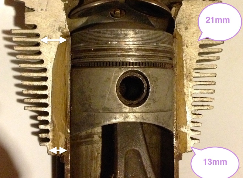
The cylinder casting has variable wall thicknesses, and is much thicker at the top of the liner than it is at the base of the casting, which means for any given interference fit, the base of the casting will give more than the top, so the liner is squeezed prorate more at the top than the bottom.
Really simple and it’s just physics. By varying the wall thickness to suit the likely temperature gradient, you can achieve tighter running clearances by tapering the bore inwards when cold. If this is combined with modern piston technology & manufacturing a quieter, more powerful air cooled engine will be the result.
A Panhard air cooled twin has tapered bores, but the cylinder casting internal bore is parallel, the liner or sleeve is parallel externally, and all the new old stock liners have been as near as damn it parallel internally. So what is causing the taper?
Here’s the answer
The cylinder casting has variable wall thicknesses, and is much thicker at the top of the liner than it is at the base of the casting, which means for any given interference fit, the base of the casting will give more than the top, so the liner is squeezed prorate more at the top than the bottom.
Really simple and it’s just physics. By varying the wall thickness to suit the likely temperature gradient, you can achieve tighter running clearances by tapering the bore inwards when cold. If this is combined with modern piston technology & manufacturing a quieter, more powerful air cooled engine will be the result.
Panhard Cylinder Liner Rebore Update 6
28/10/12 15:08
Yesterday, I machined a couple of test liners from an early Dyna engine, and after inspecting them, I decided I would do a test fit in the aluminium cylinder to see what difference there was in the bore diameter due to the interference fit.
After warming up the bare cylinder with the big propane torch, I placed the cylinder in, and rotated it into the correct position (these liners have cut outs for the crankshaft webs).
Once it was cool, I decided to take a remeasure, and see how the dimensions compared.
I started off with this measurement from yesterday, but when the sleeve or liner was placed in the cylinder I got the measurement in the second picture below.
To be honest, I thought the cylinder was larger than this picture above when I measured it this morning at around the “17.25” mark, which represents 3.36725”, but for some reason I have mislaid the picture.
Either way this represents a 0.003”-0,004” squeeze depending what picture I look at, and as I moved the micrometer out of the cylinder and took further measurements along the way, I got the following…
As the liner left the grip of the cylinder the sleeve opened up, as shown below.
At the skirt perimeter it measured even bigger still at 3.36775”, but this isn’t a huge deal, but it is interesting that a parallel bored liner deflects this much.
So yet again, we have the issue of an interference fit and the folklore surrounding a tapered bore. The last liner I machined using the Whatton actually produced a tapered bore, and the taper runs in the right direction too, because it is smallest at the hottest end.
I now know how to achieve this, and after playing with the Whatton some more, i have ascertained why it is happening. Anyway, it is an accidental product of my curiosity, and what relevance it has on real world engines is unproven. I will explore this option when the engine dyno test facility is up and running, to see if it is beneficial.
On the subject of taper, here are two pictures of a bare piston in the cylinder liner, but turned through 90º. Notice the difference in the resting height, this is due to the ovality of the piston, and the bore being smaller than the pistons nominal diameter of 85.4mm or 3.3622”
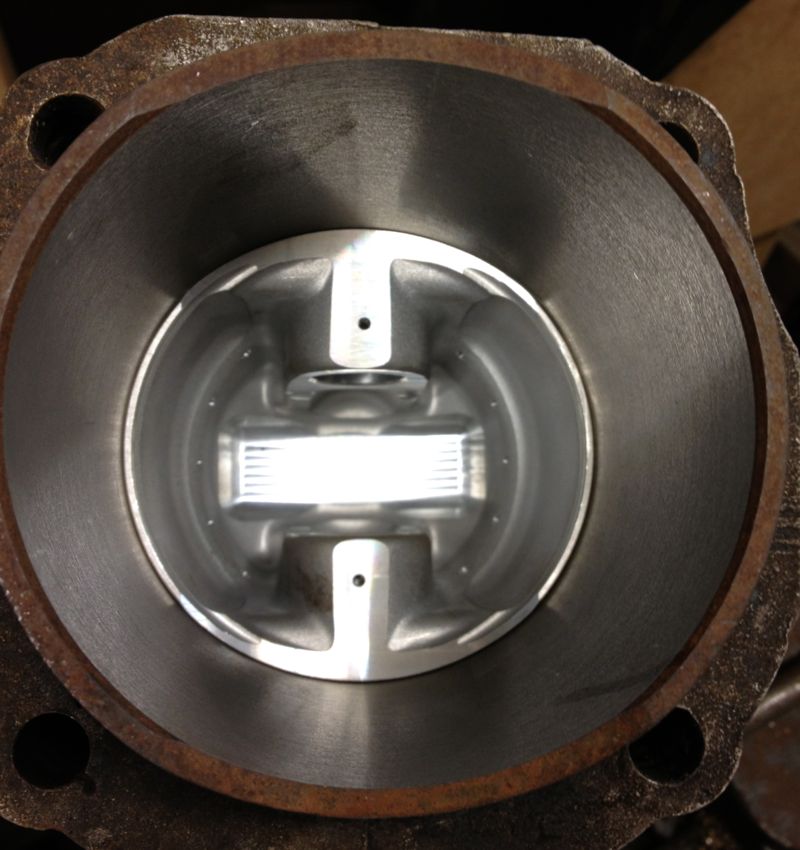
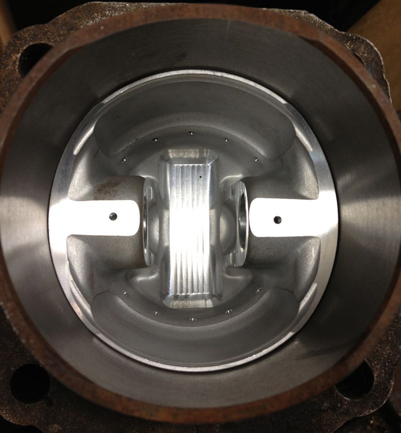
Obviously with the interference fit, the liner is slightly smaller than the expected size, as it reads 3.36320” diameter over it’s running surface, and it’s recommended value of 85.5mm equates to 3.36614”, so it’s 0.003“ undersize, or operating on a 0.001” piston to bore clearance. Actually, in modern 2 valve race engines, with very light pistons and a better spec liner material, I have seen 0.0015” clearance on an air-cooled V twin.
It did seize, because of a fuelling error, which caused it to run too hot and the piston grabbed in the bore. It was a real nice engine, but I cannot say how many horses it had at the wheel, but it was over 10% of its capacity in cubic centimetres measured in DIN RWHP, and all from a two valve head.
After warming up the bare cylinder with the big propane torch, I placed the cylinder in, and rotated it into the correct position (these liners have cut outs for the crankshaft webs).
Once it was cool, I decided to take a remeasure, and see how the dimensions compared.
I started off with this measurement from yesterday, but when the sleeve or liner was placed in the cylinder I got the measurement in the second picture below.
To be honest, I thought the cylinder was larger than this picture above when I measured it this morning at around the “17.25” mark, which represents 3.36725”, but for some reason I have mislaid the picture.
Either way this represents a 0.003”-0,004” squeeze depending what picture I look at, and as I moved the micrometer out of the cylinder and took further measurements along the way, I got the following…
As the liner left the grip of the cylinder the sleeve opened up, as shown below.
At the skirt perimeter it measured even bigger still at 3.36775”, but this isn’t a huge deal, but it is interesting that a parallel bored liner deflects this much.
So yet again, we have the issue of an interference fit and the folklore surrounding a tapered bore. The last liner I machined using the Whatton actually produced a tapered bore, and the taper runs in the right direction too, because it is smallest at the hottest end.
I now know how to achieve this, and after playing with the Whatton some more, i have ascertained why it is happening. Anyway, it is an accidental product of my curiosity, and what relevance it has on real world engines is unproven. I will explore this option when the engine dyno test facility is up and running, to see if it is beneficial.
On the subject of taper, here are two pictures of a bare piston in the cylinder liner, but turned through 90º. Notice the difference in the resting height, this is due to the ovality of the piston, and the bore being smaller than the pistons nominal diameter of 85.4mm or 3.3622”
Obviously with the interference fit, the liner is slightly smaller than the expected size, as it reads 3.36320” diameter over it’s running surface, and it’s recommended value of 85.5mm equates to 3.36614”, so it’s 0.003“ undersize, or operating on a 0.001” piston to bore clearance. Actually, in modern 2 valve race engines, with very light pistons and a better spec liner material, I have seen 0.0015” clearance on an air-cooled V twin.
It did seize, because of a fuelling error, which caused it to run too hot and the piston grabbed in the bore. It was a real nice engine, but I cannot say how many horses it had at the wheel, but it was over 10% of its capacity in cubic centimetres measured in DIN RWHP, and all from a two valve head.
Panhard Cylinder Liner Rebore Update 5
27/10/12 18:47
Using the freshly extracted & cooled cylinder liners from today, I loaded one into the Whatton boring machine jig, and started to centralise the Whatton to the liner. I usually drop the bar into the liner, centralise the machine using the three point cats paws, and tighten the base onto the mill bed.
I decided on an arbitrary test bore of 3.353” for the first cut, which is approximately 85.1mm, and just a bit oversize on the original liners.
I then started to machine the liner, but I noticed that the cut was greater on one side and not removing material from the opposite side, so I decided to recenter the Whatton at the top of the liner held in the rig. This is actually the bottom of the liner in reality...
You can see the slight ring at the top in this picture above, when I centred the liner at the top of rig, and in the picture below, the area missed in the machining.
Obviously, further machining is required, but whether it will remove this blemish inside the liner is not known until you try, so it’s time to reset the cutting tip and see if cutting a slightly larger diameter will do it. New diameter is set at 3.3665”, as shown below, by sliding the tooltip out towards the micrometer.
and then after tightening the tooltip locking screw, a quick recheck, but there’s not much difference here, about a thou, so it’s now reading 3.3655” as shown below.
Notice how the top step is taken out by machining a larger diameter, but what will happen later on?
So when the second cut is finished, I let the tooltip pass through the liner & bottom mounting plate, and recheck the tooltip bore diameter, which hasn’t changed and reads 3.3655”. All is looking good.
However a quick check with the Bowers imperial three point micrometer reveals the actual bore measurement is 3.3614”, so the Whatton is reading about 0.004” oversize.
It’s still a good result, as I can now calibrate the Whatton micrometer to the actual bore size by resetting the detent. Incidentally the wear wasn’t quite machined out of the bottom part of the liner, (top in the picture below), but as it was less than 0.0005” on diameter when measured, the final cross hatch & prior honing process will remove this comfortably.
I decided to test the calibration by machining the other liner, but this time centre the Whatton with the bottom of the rig, as I originally started to do with the above liner. This left a very slight un-machined area at the top of the liner, which is really the bottom. No rings operate in this area, so it’s not critical, but either way it will be removed by the final honing process too.
This second liner was machined at just under 3.366” using the Whatton direct reading micrometer, but after boring it measured 85.500mm with the three point Mitutoyo, and 3.3663” using the Bowers, so it’s well within my operating parameters.
A good days work, next up, reinstall the liners, and check the finished diameters, so the true clearance can be established or continue to test hone the cylinder liners using the Delapena hone. For the latter, I will have to CAD up a drawing, as I need to make a rig to hold the liners, before I can hone them properly. It’s not worth using the Whatton set up, as it’ll be too much disruption.
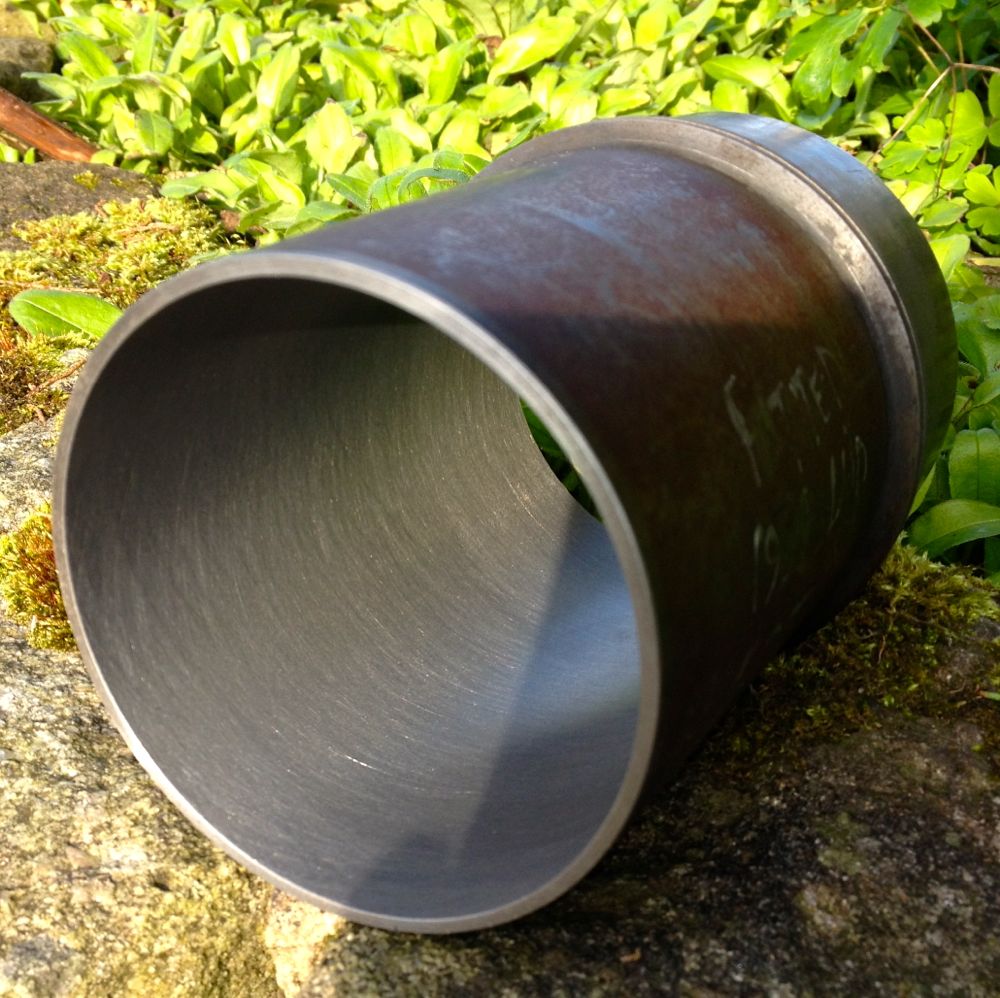
Panhard Cylinder Liner Removal
27/10/12 13:07
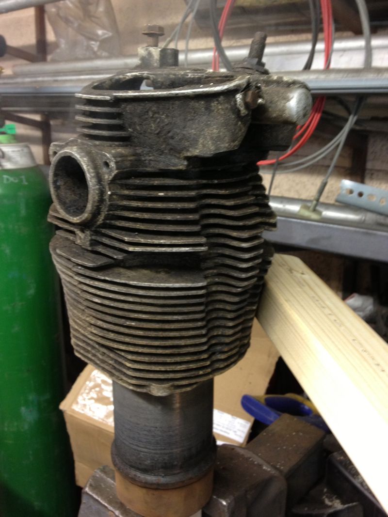
As usual I have been working away, and work has been taking all my time, but today I collected some test cylinders from John Passfield. These were early Dyna ones, and I just needed the liners to machine.
First you have to get them out of the cylinders, Panhard suggests using a U shaped gas torch, but to be honest any large roofing torch, or an electric fan oven will do it. The latter is a no no if it is in the house, as the old oils etc leave a nice odour that Febreze won’t shift!
So after placing the cylinder on a lump of wood, clamped to a vice, using a large soft flame aim for the area around the finning where the nuts go onto the crankcase studs ( the metal is thickest around here), and keep moving the flame around the cylinder to spread the heat evenly.
After a minute or so, the liner will drop partially and that’s why I have a piece of wood below, for it to land on. In realty it doesn’t drop to far, as the liner tends to stick to the wood, but if you tap the cylinder, it will drop clear of the aluminium cylinder.
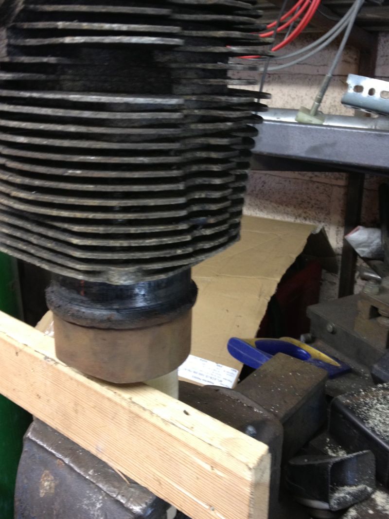
Easy really, but they will be VERY hot, so be careful and wear a heatproof glove, and let them cool naturally, which was easy today, as it was 2ºC outside.
First you have to get them out of the cylinders, Panhard suggests using a U shaped gas torch, but to be honest any large roofing torch, or an electric fan oven will do it. The latter is a no no if it is in the house, as the old oils etc leave a nice odour that Febreze won’t shift!
So after placing the cylinder on a lump of wood, clamped to a vice, using a large soft flame aim for the area around the finning where the nuts go onto the crankcase studs ( the metal is thickest around here), and keep moving the flame around the cylinder to spread the heat evenly.
After a minute or so, the liner will drop partially and that’s why I have a piece of wood below, for it to land on. In realty it doesn’t drop to far, as the liner tends to stick to the wood, but if you tap the cylinder, it will drop clear of the aluminium cylinder.
Easy really, but they will be VERY hot, so be careful and wear a heatproof glove, and let them cool naturally, which was easy today, as it was 2ºC outside.
Panhard Cylinder Liner Rebore Update 4
13/10/12 19:00
One of the areas I had to improve was the direct reading of the Whatton Boring Bar now that I have converted it to some readily available indexable tooltips.
The dedicated micrometer was not touching the tooltip, because the tooltip was lower than the anvil. A few moments on the lathe to test the idea, and bingo.
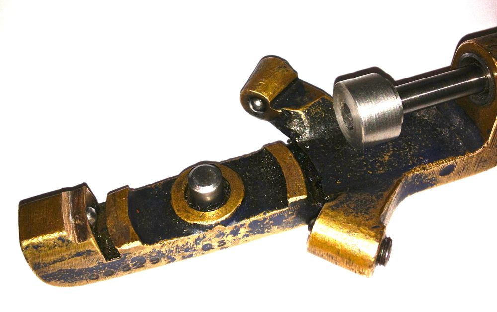
Here it is in situ, that’s attached to the anvil, with the micrometer fixed to the boring bar.
I just have to set the tip position and to do another test bore to establish the actual bore size measured by the three point bore micrometer versus the indicated reading of the Whatton micrometer.
The dedicated micrometer was not touching the tooltip, because the tooltip was lower than the anvil. A few moments on the lathe to test the idea, and bingo.
Here it is in situ, that’s attached to the anvil, with the micrometer fixed to the boring bar.
I just have to set the tip position and to do another test bore to establish the actual bore size measured by the three point bore micrometer versus the indicated reading of the Whatton micrometer.
Panhard Cylinder Liner Rebore Update 3
07/10/12 17:02
Yet again, I could only manage a few hours on the Panhard stuff, but I have finally cured the machining issues I had reboring the liners.
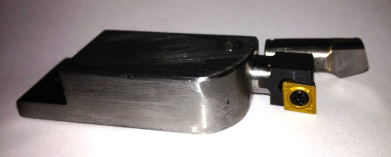
This is the set up as it stands now, long tooltip holder, modified LH boring bar with indexable CCMT insert, but unfortunately the longer tooltip holder fouls the boring bar micrometer body, so I cannot take a direct measurement using it at the moment. A little tweak with a Dremel should solve this, but I’ll do it another day, when I make a sleeve for the anvil, so it contacts the lower cutting surface of the new indexable insert.
On examination the bore was truly round, had a good consistent surface finish and measured 86.03 mm at the top, middle and bottom. I have eliminated the chatter that caused the rippling to the bore last weekend, by using the larger tooltip holder, but I got a slight scoring at three points afterwards. However, a slower feed speed, as well as tightening the spring loaded gibs, and increasing the pressure on the boring bar sleeves to eliminate the sliding play stopped any further occurrences.
Interestingly the original induction motor runs lot cooler with the vacuum pump motor coupling, which has a rubber cush drive rather than a leather or felt pad, and even with the increased loadings and therefore additional effort required to move the boring bar ,through the slides, there is no increase in temperature.
The ripple to the bores was caused by me inadvertently using the shorter tooltip holder, which is really made for the smaller bores sizes. The grub screw which is designed to lock the tooltip holder in position, was in fact gripping the adjusting plate, and so the tooltip holder was vibrating and moving on the screw adjuster.
Considering I didn’t have a manual, or know of any other person with one of these, losing just one liner to teething issues is a good result.
Here is the test cylinder after honing, but not washed yet though.
Panhard Cylinder Liner Rebore Update 2
29/09/12 20:09
Today I collected the tooltips that I had modified, and also fitted the vee belts, that had arrived in the post earlier in the week, to the Whatton Boring Bar. After struggling to get them onto the pulleys, and replacing the top cover, I fitted a new indexable tips to the short tool tip holder.
I centralised the bar over the liner and went to adjust the tip using the micrometer, and discovered the tooltip was not catching the micrometer anvil, because it cuts slightly lower now it misses the anvil tip. I will have to make a larger diameter adaptor to sleeve & cap over the anvil of the micrometer, which might add say 0.1” thick overall externally, to make reading the actual size easier. A bit of machined silvered steel to the rescue, aided by a helpful chap on a tool grinder down the road.
If you look at the picture above you can see the cutting edge is much lower than the centre line of the old carbide tip.
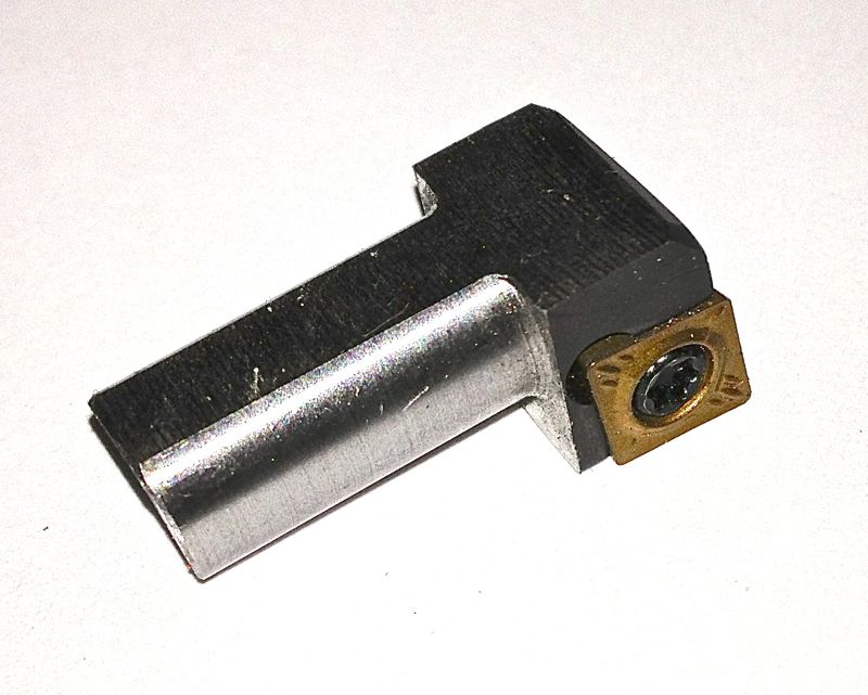
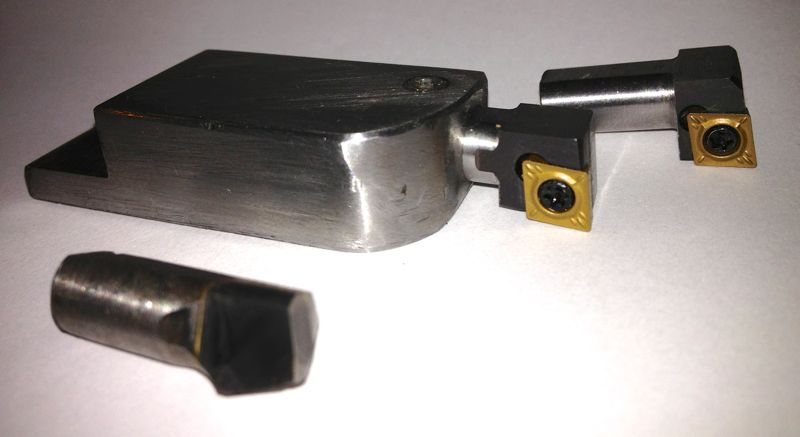
This is the 12mm square shank tool converted in the long holder with a 8mm square shanked version in the background. The original tip is in the foreground.
I started to machine the liner, and the motor never stalled at all, so finally a little success, and the first shallow cut was of a very good surface finish. Next I tried a slower roughing cut, and after about halfway down the liner, some strange swishing/grating noises started to reverberate from the bar. I couldn’t see what was happening, as the heavier cut was creating a fair amount of dust, (note to me, need a vacuum source to remove cutting dust). When I looked at the bore after the cutting process had finished, I had a perfect bore for about half the length of the liner, then a series of ridges or ringed undulations. :eek
I had to leave off at that point and sort out a few other jobs, but it would appear the back edge of the tooltip was catching the bore, which is easily remedied by grinding an increased taper behind the tooltip face, but more importantly & slightly worrying is the only way it could ring the bore was if the tooltip was moving. I am going to try with the longer tooltip holder to see if the short tool holder was rocking slightly, and therefore pushing into the liner. I will also double check the gigs that take up the play on the bar as it travels downwards. The latter wasn’t an issue before, but I have to check.
Anyway I am pleased that the motor/tooltip stall with the original carbide tipped tools isn’t repeating itself, just got to work on this new problem.
I centralised the bar over the liner and went to adjust the tip using the micrometer, and discovered the tooltip was not catching the micrometer anvil, because it cuts slightly lower now it misses the anvil tip. I will have to make a larger diameter adaptor to sleeve & cap over the anvil of the micrometer, which might add say 0.1” thick overall externally, to make reading the actual size easier. A bit of machined silvered steel to the rescue, aided by a helpful chap on a tool grinder down the road.
If you look at the picture above you can see the cutting edge is much lower than the centre line of the old carbide tip.
This is the 12mm square shank tool converted in the long holder with a 8mm square shanked version in the background. The original tip is in the foreground.
I started to machine the liner, and the motor never stalled at all, so finally a little success, and the first shallow cut was of a very good surface finish. Next I tried a slower roughing cut, and after about halfway down the liner, some strange swishing/grating noises started to reverberate from the bar. I couldn’t see what was happening, as the heavier cut was creating a fair amount of dust, (note to me, need a vacuum source to remove cutting dust). When I looked at the bore after the cutting process had finished, I had a perfect bore for about half the length of the liner, then a series of ridges or ringed undulations. :eek
I had to leave off at that point and sort out a few other jobs, but it would appear the back edge of the tooltip was catching the bore, which is easily remedied by grinding an increased taper behind the tooltip face, but more importantly & slightly worrying is the only way it could ring the bore was if the tooltip was moving. I am going to try with the longer tooltip holder to see if the short tool holder was rocking slightly, and therefore pushing into the liner. I will also double check the gigs that take up the play on the bar as it travels downwards. The latter wasn’t an issue before, but I have to check.
Anyway I am pleased that the motor/tooltip stall with the original carbide tipped tools isn’t repeating itself, just got to work on this new problem.
Panhard Cylinder Liner Rebore Update 1
23/09/12 14:18
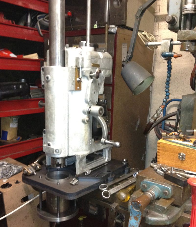
I recently bought an upgraded version of the original motor off eBay, a 370W or 1/2 horsepower with the correct baseplate. However when I tried to swap the motor over today, I discovered the increased height or length didn’t allow it to clear the main casting. I had to revert back to the old motor, but I did use the cush drive off the vacuum pump, which was more concentric than the old part, and the boring machine is much quieter, with less vibration.
I have been doing all the attempted cuts so far with a single belt, and really struggled to fit one belt let alone the two that are required. Today I managed to fit the sister belt, a Z16 428 Ld, 410 Li onto the double fee pulley. It was at this point I notice the other belt was slightly stretched and greasy. The frayed edges are a result of a woodruff key being fitted incorrectly by the previous owner, it should never had one, as it had a hardened circular pin, that located in a vertical keyway. The woodruff key grabbed and wore itself out, and caused the belt to run at an angle, so cutting the edges.
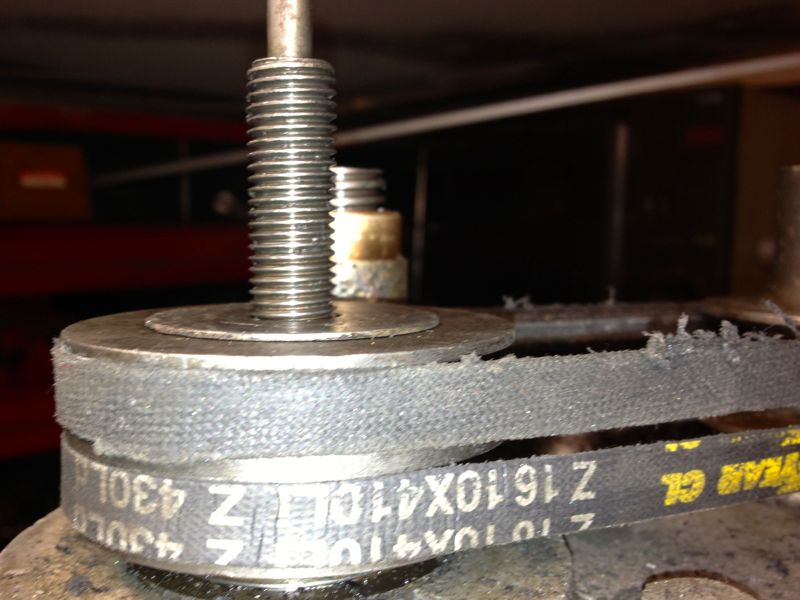
I cannot guarantee I will get the same, so I have ordered two new belts to replace the stretched one. I also have a novel way (new to me) of getting the vee belt onto the pulleys, which doesn’t involve taking the pulleys off and sliding them down the shafts, however I cannot tell you how, as it might mean a silly person could lose a finger. Suffice to say, I cannot turn the pulleys by hand to get the belt to fall into its respective groove without it needing some electrical assistance.
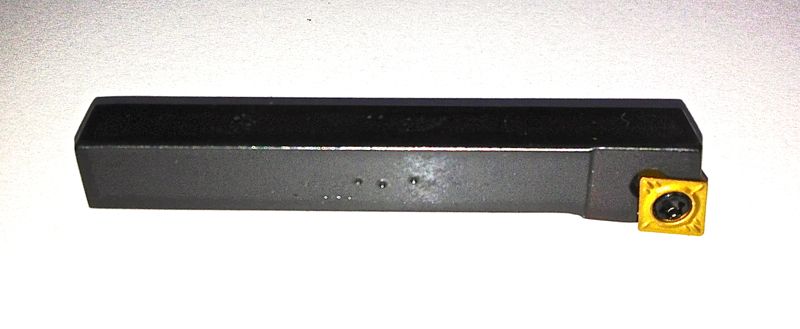
The tooltips were scheduled to be done today, but I am pleased they haven’t been done yet as I have bought another LH boring tool to convert, and so I don’t have to pay for another set up charge.
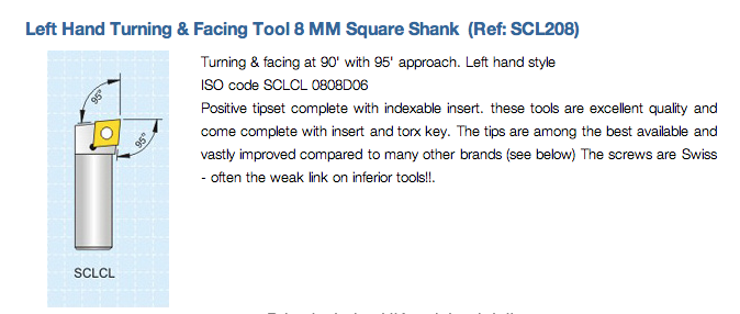
It’s 8mm square shanked, indexable and takes CCMT inserts, but I am having it shortened and made 5/16” round with a flat put on it to lock it off square in the boring head tooltip carrier.
Hopefully, I will be able to use them soon, within the first week of October, in the boring machine, and then get the test liner analysed for surface finish, squareness etc at the local engineering works. If all works out, I will be able to rebore Panhard liners in the future to very precise standards.
I have been doing all the attempted cuts so far with a single belt, and really struggled to fit one belt let alone the two that are required. Today I managed to fit the sister belt, a Z16 428 Ld, 410 Li onto the double fee pulley. It was at this point I notice the other belt was slightly stretched and greasy. The frayed edges are a result of a woodruff key being fitted incorrectly by the previous owner, it should never had one, as it had a hardened circular pin, that located in a vertical keyway. The woodruff key grabbed and wore itself out, and caused the belt to run at an angle, so cutting the edges.
I cannot guarantee I will get the same, so I have ordered two new belts to replace the stretched one. I also have a novel way (new to me) of getting the vee belt onto the pulleys, which doesn’t involve taking the pulleys off and sliding them down the shafts, however I cannot tell you how, as it might mean a silly person could lose a finger. Suffice to say, I cannot turn the pulleys by hand to get the belt to fall into its respective groove without it needing some electrical assistance.
The tooltips were scheduled to be done today, but I am pleased they haven’t been done yet as I have bought another LH boring tool to convert, and so I don’t have to pay for another set up charge.
It’s 8mm square shanked, indexable and takes CCMT inserts, but I am having it shortened and made 5/16” round with a flat put on it to lock it off square in the boring head tooltip carrier.
Hopefully, I will be able to use them soon, within the first week of October, in the boring machine, and then get the test liner analysed for surface finish, squareness etc at the local engineering works. If all works out, I will be able to rebore Panhard liners in the future to very precise standards.
Panhard Cylinder Liner Rebore Test
06/08/12 23:00
Finally managed to machine the support plate for the cylinder liner to the right size. The lathe wasn’t able to do it, so I used the Whatton boring machine. Unfortunately, the Whatton really struggled with the work hardened laser cut plate, and the tooltips got hammered, but finally it was done.
The cylinder liner can now be held in situ, whilst it’s being rebored.
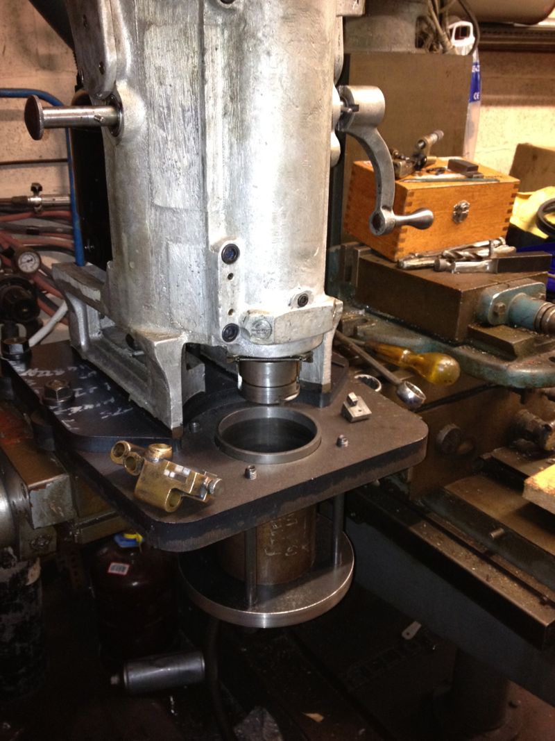
Everything is almost working OK, but I need to refine the belt tension, and the tooltip selection. I think I need to convert the Whatton to indexable tooling, as well as look at the pulley & V belt some more, as the tooltip can stall in the bore with a heavier cut.
The cylinder liner can now be held in situ, whilst it’s being rebored.
Everything is almost working OK, but I need to refine the belt tension, and the tooltip selection. I think I need to convert the Whatton to indexable tooling, as well as look at the pulley & V belt some more, as the tooltip can stall in the bore with a heavier cut.
Panhard Piston Update
11/06/12 21:17
Just had an update from the piston company, and they have sent me a grainy picture of the piston part finished.
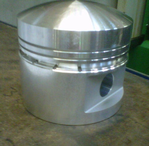
The underside still needs machining, and the barrelling etc is still to do, but it’ll give an idea of how much shorter & lighter the piston will be.
The underside still needs machining, and the barrelling etc is still to do, but it’ll give an idea of how much shorter & lighter the piston will be.
Panhard piston design finalised
07/04/12 09:52
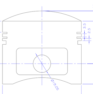
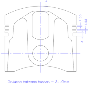
This is the latest iteration of the high compression Panhard piston that I am having made for Brian’s engine, and it will be substantially lighter than the OEM set up, but there is a slight compromise with the weight, because I want to use the standard cylinder and liner positions.
This piston will be used to modernise & improve the standard flat twin engine, and be a suitable replacement for the majority of the air cooled Panhard engines. It will need a new piston pin bush to cater for the standard crankshaft, but this is required whatever parts are fitted to the engine, as the original set up leaves little to be desired. This piston set will include a fully floating pin with improved lubrication to the piston pin bosses via cross drillings from the behind the oil control ring.
As the piston offers a higher compression over standard, I will be making some conversion shims to lower this for owners that want to run the standard ignition & carburation.
The new bore size will be 85.51mm, and the capacity will now be 861 cc, but if you want to play with different combinations, I created an engine size calculator here
