Catalytic Converter Replacement Exhaust #4 (updated)
Wed 21 Dec 2011 Filed in: GTS1000 Exhaust
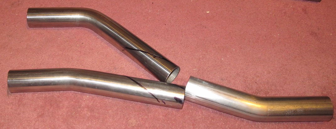
I collected the raw tubes earlier in the week, which is enough for 4 pieces, but still looking for somebody to do the smaller pipes that the downpipes fit into. This means I can start the 2-1 and outlet bend assembly, but obviously I really need to start at the front first, so these down pipe bends are a bit of a nuisance.
.
.
Comments
Rubber sheet that fits over the airbox lid
Sun 30 Oct 2011 Filed in: GTS1000 Part
I finally got round to flattening out this rubber sheet, scanning it and drawing around it in CAD.
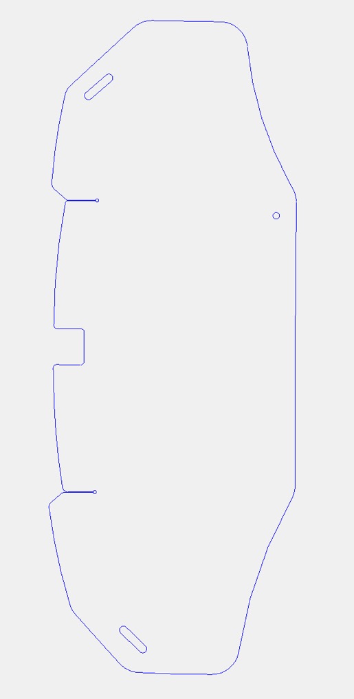
Here is the 2D .dxf file, contact me if you want it in another format.
rubber_shield.dxf
Here is the 2D .dxf file, contact me if you want it in another format.
rubber_shield.dxf
Catalytic Converter Replacement Exhaust #4
Fri 21 Oct 2011 Filed in: GTS1000 Exhaust
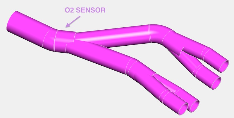
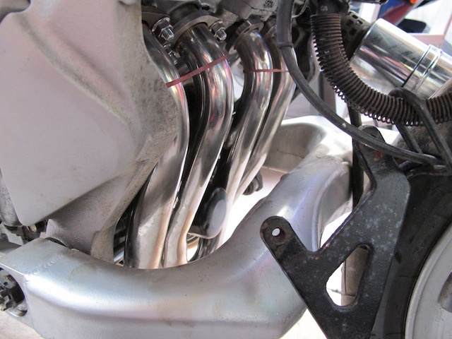
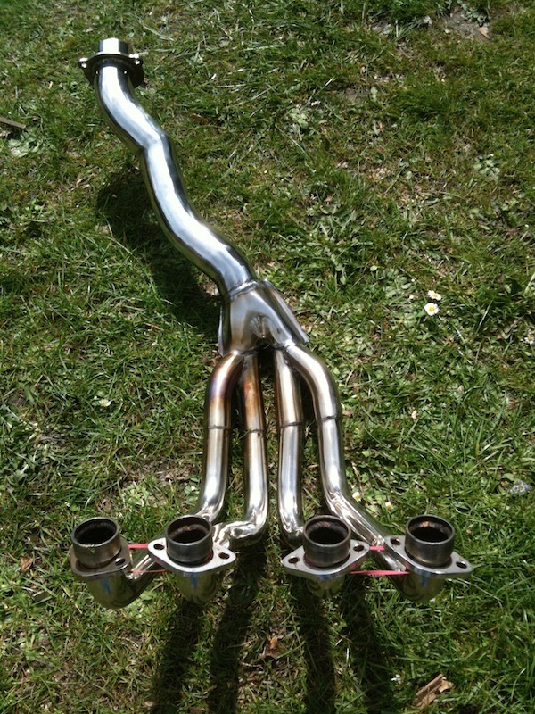
This is the start of a CAD model which is based on my prototype collector, and this drawing is my way of working out what angle & length mandrel bends I need to fabricate a 4-2-1 collector to replace the catalytic converter. The front pipe merge collectors are well sorted, just got to do a little more work on two of the three remaining bends.
Looks ever more promising, as I have found a mandrel bender near me too.
How to fit a one piece exhaust to a GTS1000.
Sat 24 Apr 2010 Filed in: GTS1000 Exhaust
This has to be the easiest way to fit a one piece exhaust... jack it up with an engine crane like this
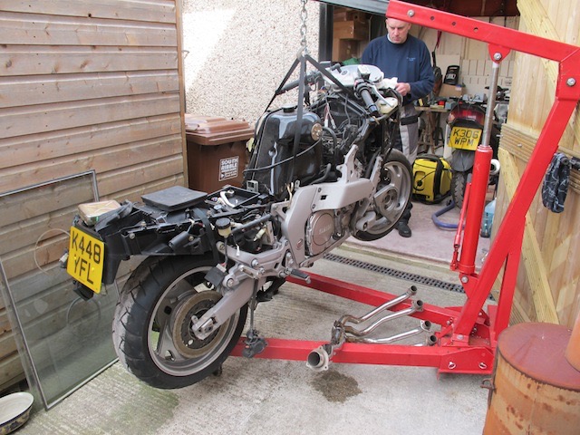
Undo the front swingarm bolts and pull the arm out of the way, and just strap it up to something nearby, like this and this.
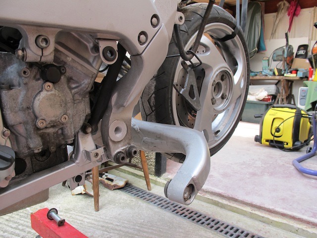
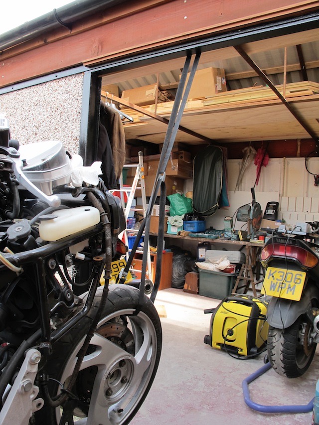
and when it's done...it looks like this.
Total time probably less than an hour and a half.
Undo the front swingarm bolts and pull the arm out of the way, and just strap it up to something nearby, like this and this.
and when it's done...it looks like this.
Total time probably less than an hour and a half.
Catalytic Converter Replacement Exhaust #3
Sat 24 Apr 2010 Filed in: GTS1000 Exhaust
Finally got round to finishing this, only get one day in seven to play at the moment. To be honest, it needs a little more work, more polishing etc, slight tweak to the final bend after the collector, before I make the final version for the GTS.
Awaiting some feedback from the local tube benders, as to what they can do for me, and talked it over with the stainless steel welder/fabricator. Will start a jig once, I know what these can do. Definitely looking at four separate downpipes though, as pulling the front arm away is more work then it needs to be.
Will be using larger primary/headers/downpipes to suit higher performance applications, but it will not be detrimental for stock ones either.
MicroSquirt Module
Tue 30 Mar 2010 Filed in: MicroSquirt
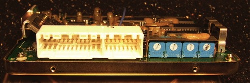
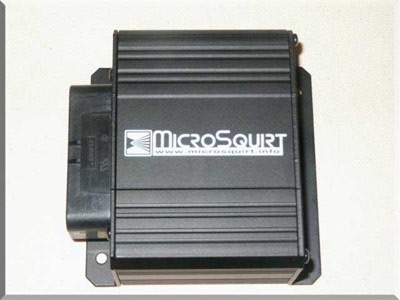
This is an FJ1200 ABS ECU case after the circuit board is removed. It is fitted with a cut down DIY Autotune PNP Nippon Denso Board adapter, that fits my cut down Toyota female connector, that incidentally matches the GTS1000 wiring loom connectors. On the right is the MicroSquirt Module, a lower cost version of the cased MicroSquirt, that allows for a few extra pin outs. When this is combined with the MSExtra code, it will give me 4 ignition outputs and four injection outputs.
I need to combine this with a driver board, so I have squeezed Jean Belanger's from www.jbperf.com excellent 4x4 board into the space available at the bottom. The image below represents a dry fit, just to check the spatial requirements, and is missing the RXTX serial connector & a discreet bootload switch for programming the device.
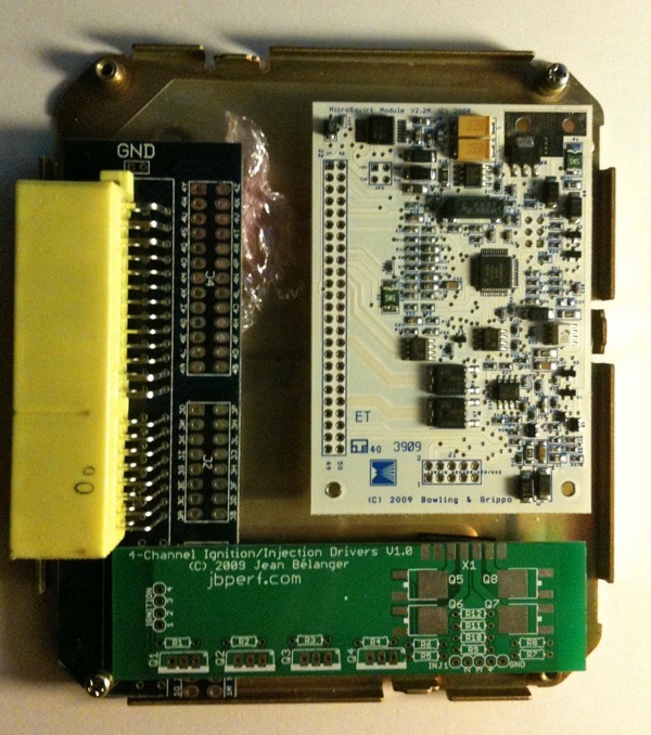
Definitely not bad compared to the OEM ECU package, and much more capable, in a smaller package.
I need to combine this with a driver board, so I have squeezed Jean Belanger's from www.jbperf.com excellent 4x4 board into the space available at the bottom. The image below represents a dry fit, just to check the spatial requirements, and is missing the RXTX serial connector & a discreet bootload switch for programming the device.
Definitely not bad compared to the OEM ECU package, and much more capable, in a smaller package.
Red GTS1000 running MS Extra using cased MicroSquirt Day 8
Sat 27 Feb 2010 Filed in: MicroSquirt
Yet another attempt at a cold start, but for some reason I noticed the ASE Percentages is cutting out too quickly, so I increased cycles hugely in the ASE Taper dialog box. Didn't really seem to make much difference, but WUE is the key...this engine likes quite a bit of fuel on coldish 8ºC starts, but soon drops in richness requirements as the bike warms.
Read More...
Read More...
Red GTS1000 running MS Extra using cased MicroSquirt Day 7
Fri 26 Feb 2010 Filed in: MicroSquirt
Another day, another cold start, and still it doesn't run on after catching. At least the Priming and Cranking Pulses are doing their bit. I tweaked the WUE and ASE Percentages and it caught OK, so another day is needed to test these revised settings... Read More...
Red GTS1000 running MS Extra using cased MicroSquirt Day 6
Thu 25 Feb 2010 Filed in: MicroSquirt
Another attempt at a cold start...coolant temperature 8ºC...doubled the injection priming pulses (from 1ms to 2ms) and hit the button, quick fire on the button (that's an improvement) but it dies instantly. OK, so boost the WUE (Warm Up Enrichment) and mod the ASE (After Start ) Percentages, and hit the button again. Engine starts very quickly, on closed throttle, but dies again within a second...
Read More...
Read More...
Red GTS1000 running MS Extra using cased MicroSquirt Day 5
Wed 24 Feb 2010 Filed in: MicroSquirt
Another day and another cold start test, and it wouldn't fire, so I swapped back to the stock ECU and it fired straight up. I swapped the MicroSquirt in and with the revised settings it started straight away, but fast idle was about 800 higher than stock, and the conclusion is I need to look at my cranking pulse widths in more detail. The throttle response dropped off unexpectantly after a short time & then I realised I had run out of fuel... Read More...
Red GTS1000 running MS Extra using cased MicroSquirt Day 4
Tue 23 Feb 2010 Filed in: MicroSquirt
Since that last run day before yesterday, I have been reworking my VE tables and Ignition, looking at the Cranking and Warm Up Enrichment, After Start Taper and Percentages and today I uploaded the latest configuration. It started on the bike after further tweaks to the cranking and the fast idle was around 2200 and dropping gradually to 1100... Read More...
Red GTS1000 running MS Extra using cased MicroSquirt Day 3
Sun 21 Feb 2010 Filed in: MicroSquirt
I hit the road at 15:30 and 2 hours later the 5K stumble was done and dusted. The engine revs cleanly from 1100-11000K and rips on the throttle. It was absolutely awesome...and I haven't even used the full capability of the MSExtra code... Read More...
Red GTS1000 running MS Extra using cased MicroSquirt Day 2
Sun 14 Feb 2010 Filed in: MicroSquirt
The throttle response up to 5000 rpm is very nice, but there is a sync issue after this. I am using the B&G adaptor loom, which has a signal diode on the crank trigger, but I was unable to swap it for a resistor, as I didn't have any. I just have to do some more work on the cold start settings and after start enrichments... Read More...
MicroSquirt VR2 issues
Sat 14 Nov 2009 Filed in: MicroSquirt
I was having issues with my cased Microsquirt, and detecting the cam sensor on VR2. It turns out the shared ground with the crank sensor on VR1 is the issue, as well as the decreased sensitivity on the VR2 circuit. Read More...
Crankshaft & cam rig
Mon 15 Dec 2008 Filed in: MicroSquirt
It has been a while since I have been able to do anything on this project. After I built the crankshaft rig for the Thunderace, I saw a post on the MicroSquirt forum and realised I’d need to simulate a camshaft sensor input too. Trouble was although I had a camshaft I could use, suspending it between centres and driving it by chain seemed a little OTT. I decided on a wheeled tyre that would run on the circular part of the crank web, and by running at half crank speed, it would do the job. In reality it probably wasn’t the wisest choice, as it took a fair bit of tweaking and I still need to get a one piece O ring. There are three superglued together on the cam wheel.
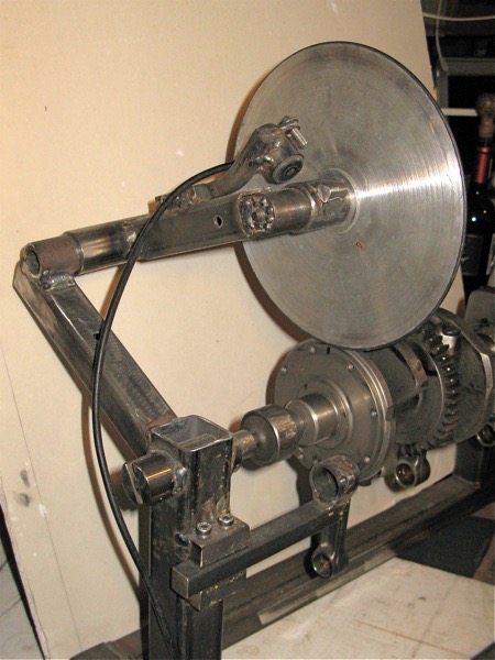
Crank sensor not in place yet
After spinning up the cam wheel and using the hand held scope, I was getting too much interference to get any real info : (
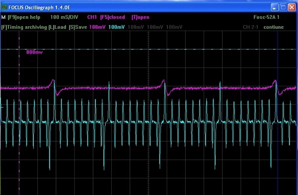
Next step was to get a 2 channel oscilloscope that would hook into the laptop, as the hand held Velleman was only single channel. A quick peek on eBay and a few weeks later, a 5 channel USB device dropped through the letterbox.
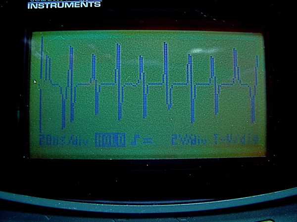
After loading the software, finding another oscilloscope probe and spinning it up, this was the result. Pink is the cam sensor, light blue the crank.
Looking good so far I thought, so I bootloaded the Tooth Analyser code into the MicroSquirt, and opened the Tach Ref software, so that I could see what the MicroSquirt would see, and nothing happened, Disappointed I powered the unit up. Set the ECU code =2 and the LOW BATTERY in red never went away. Checked the connections, checked the MicroSquirt voltage, checked the bootload ground voltage, reloaded the 2.888a embedded code, but still no battery voltage...nothing seems to make it run.
Checked the MicroSquirt website for documentation, and I hope I haven’t got a bootload lockout (it’s a version 1). This is the second time this fault has happened and last time I was clumsily checking the voltages with some new multimeter leads, that were too big and killed a track. I’ll not do the same this time...checked as much as I can, here’s hoping a guru will help me out with a pearl of wisdom.
Crank sensor not in place yet
After spinning up the cam wheel and using the hand held scope, I was getting too much interference to get any real info : (
Next step was to get a 2 channel oscilloscope that would hook into the laptop, as the hand held Velleman was only single channel. A quick peek on eBay and a few weeks later, a 5 channel USB device dropped through the letterbox.
After loading the software, finding another oscilloscope probe and spinning it up, this was the result. Pink is the cam sensor, light blue the crank.
Looking good so far I thought, so I bootloaded the Tooth Analyser code into the MicroSquirt, and opened the Tach Ref software, so that I could see what the MicroSquirt would see, and nothing happened, Disappointed I powered the unit up. Set the ECU code =2 and the LOW BATTERY in red never went away. Checked the connections, checked the MicroSquirt voltage, checked the bootload ground voltage, reloaded the 2.888a embedded code, but still no battery voltage...nothing seems to make it run.
Checked the MicroSquirt website for documentation, and I hope I haven’t got a bootload lockout (it’s a version 1). This is the second time this fault has happened and last time I was clumsily checking the voltages with some new multimeter leads, that were too big and killed a track. I’ll not do the same this time...checked as much as I can, here’s hoping a guru will help me out with a pearl of wisdom.
Crankshaft rig
Sat 06 Sep 2008 Filed in: MicroSquirt
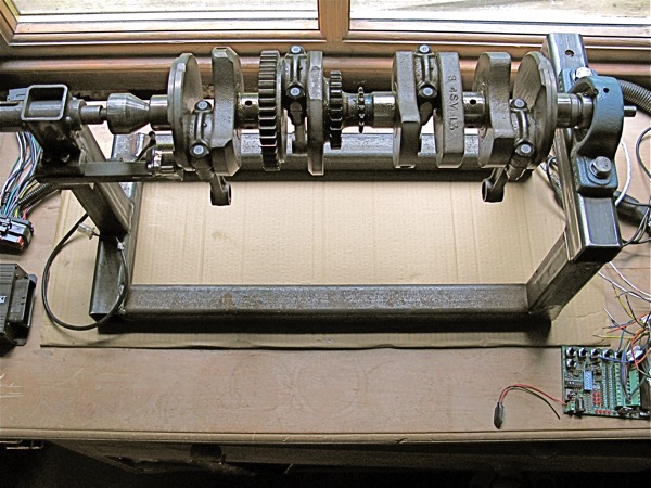
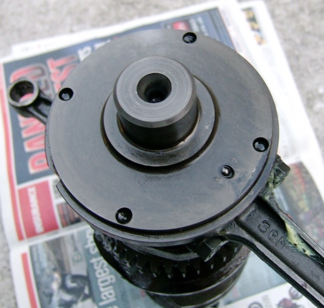
I built a crankshaft rig, to save me having to work outside. I use a cordless drill on the right hand side to rotate the crank. I use first gear on the drill to simulate a cranking speed of upto 400rpm, and second gear to replicate an idle speed of 1100rpm. I managed to get a trace of the VR signal using a handheld Velleman scope, which unfortunately doesn’t have a USB output, so I have to take a photo instead.
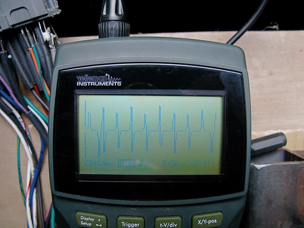
A better view of the trace can be seen below, which has been adjusted in iPhoto to improve clarity.
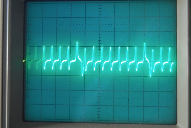
These are virtually identical to an FZ700 trace that a guy called frost on the MicroSquirt forums has posted which I have included as it better than my efforts, however I wasn’t that fussed about using a 240V CRT oscilloscope in the rain outside on a running bike. :lol:
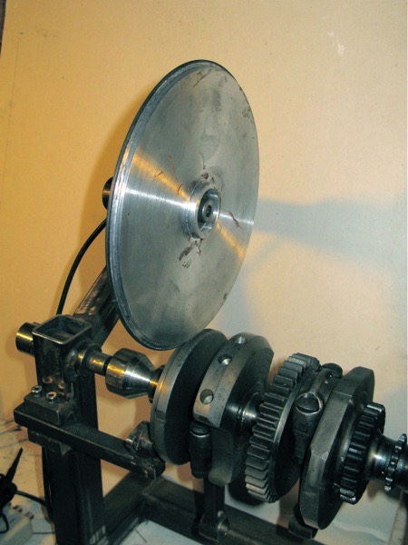
This is a picture of the crank sensor end, notice the large milled slot and the plugged big end oil drilling at 4 o’clock.
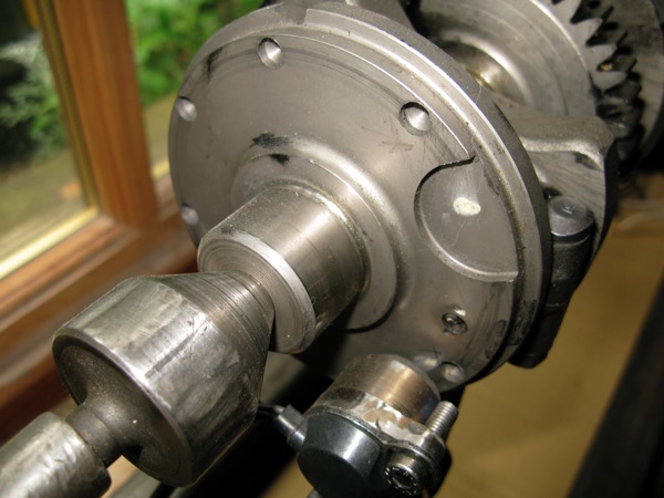
Now all I have to do is boot a new program into the MicroSquirt and power the crank up. The new program logs the pulses from the VR sensor, and hopefully it will shed some light on what direction this project can take next. I am reluctant to make a hardware change to the crank (machine the slot and rebalance the crank), so I’d really like to explore the software options first. Unfortunately this is new territory for me, so I expect a delay whilst I raise my game.
GTS1000 ECU connectors 64P
Thu 28 Feb 2008 Filed in: MicroSquirt
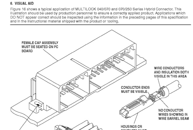
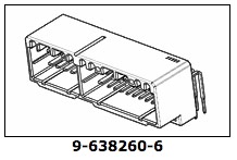
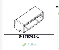
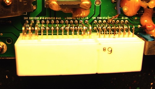
You gotta laugh sometimes, as I was watching something on eBay, and I got notified of it ending soon. It was a series of Multilock connectors that were coming up, that didn't look anything like a GTS1000 ECU version, but guess what...this is a front view
and this is an overall three quarter view
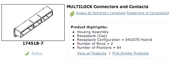
and two outta three ain't bad
So there is another part out there that will do, all you have to do is cut off the surplus part or use it for the Wideband O2 sensor option or Coil On Plug capability that will come with the MicroSquirt Sequencer, when that happens though I have no idea.
and this is an overall three quarter view
and two outta three ain't bad
So there is another part out there that will do, all you have to do is cut off the surplus part or use it for the Wideband O2 sensor option or Coil On Plug capability that will come with the MicroSquirt Sequencer, when that happens though I have no idea.
GTS1000 ECU connectors
Sun 24 Feb 2008 Filed in: MicroSquirt
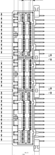
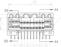
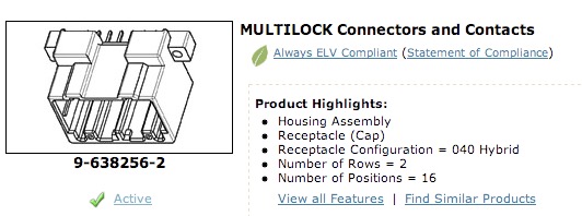
Just a quick update on these AMP connectors. The OEM ECU has one 42 pin (42P) socket, or horizontal cap housing, but being a newbie to these connectors I just found out they we made as hybrids. So you got a mixture of pins, 040 and 070 varieties. Our bikes have a 26P hybrid on the left, and a 16P on the right. Nearly all 26P cap housing hybrids have a 6-10-4 arrangement when viewed from the front and going left to right.
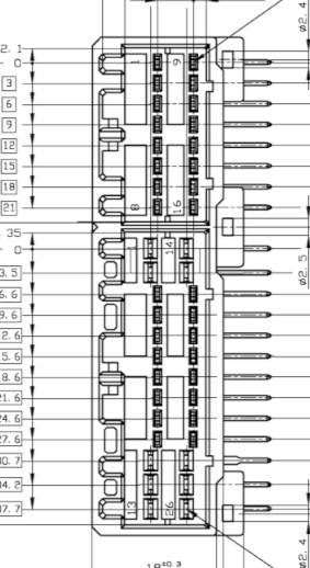
The 26P wiring loom hybrid plug was marked 10763 which it turns out was not a reference number you could search for, but I did find it on a pdf.
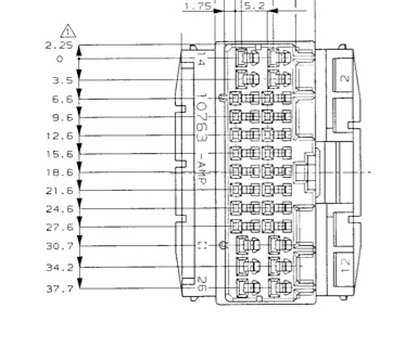
This another version of the hybrid connector, the same thing but just swapped left and right
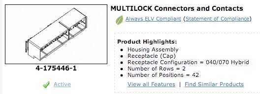
In order to interface the AMPSEAL connector I could buy a 42P vertical cap housing, sleeve the wires with shrink wrap and solder to the back of the 42P contacts. The other options are to use a 26P hybrid cap housing and a 16P cap housing or plug connector. As these connectors were made some time ago, having a degree of flexibility is useful as availability and becoming obsolete is an issue now.
16P left hand ECU equivalent female socket
 This is a reversed ECU connector.
 26P Hybrid 040/070 Multilock
 Detail from 26P hybrid Multilock 040/070
16P Vertical cap housing
The 26P wiring loom hybrid plug was marked 10763 which it turns out was not a reference number you could search for, but I did find it on a pdf.
This another version of the hybrid connector, the same thing but just swapped left and right
In order to interface the AMPSEAL connector I could buy a 42P vertical cap housing, sleeve the wires with shrink wrap and solder to the back of the 42P contacts. The other options are to use a 26P hybrid cap housing and a 16P cap housing or plug connector. As these connectors were made some time ago, having a degree of flexibility is useful as availability and becoming obsolete is an issue now.
16P left hand ECU equivalent female socket
This is a reversed ECU connector. 26P Hybrid 040/070 Multilock Detail from 26P hybrid Multilock 040/07016P Vertical cap housing
GTS1000 ECU Plug Connectors
Sun 24 Feb 2008 Filed in: MicroSquirt
The easiest way to get the MicroSquirt to integrate with the GTS1000 loom, is to make an interconnect between the two. I am on the look out for some inline female connectors and pins that will linkup to the existing ECU loom plugs.
The connector looks like this, and it is an AMP Multilock 040/070 Hybrid component.
These connectors seem to be quite hard to get hold of, but they were quite common and fitted to Toyotas as this loom shot shows
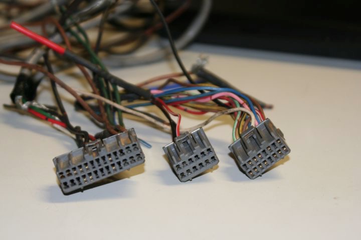
The GTS1000 loom has two connectors that are the same as the left and right ones in this pic above, the left one is a 26P and the right a 16P type, but the left connector has two different sized pins, which you can just make out four on the left and six on the right.
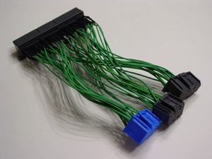
Fortunately, there are quite a few folks out there that like these Toyotas, and there is a company making bespoke loom adaptors for them, and after lurking on a few forums found this link. http://www.boomslang.us They make products like this.
Time to send an email.
The connector looks like this, and it is an AMP Multilock 040/070 Hybrid component.
These connectors seem to be quite hard to get hold of, but they were quite common and fitted to Toyotas as this loom shot shows
The GTS1000 loom has two connectors that are the same as the left and right ones in this pic above, the left one is a 26P and the right a 16P type, but the left connector has two different sized pins, which you can just make out four on the left and six on the right.
Fortunately, there are quite a few folks out there that like these Toyotas, and there is a company making bespoke loom adaptors for them, and after lurking on a few forums found this link. http://www.boomslang.us They make products like this.
Time to send an email.
GTS1000 crankshaft & camshaft triggers
Sun 24 Feb 2008 Filed in: MicroSquirt
This is the GTS1000 crankshaft trigger detail, the camshaft trigger is the camshaft lobe passing close to a variable reluctance sensor. If you look on the MicroSquirt forum, there is a link to the MSextra section. This is an additional code area for these little boxes, and it looks like they support the GTS1000 system, which is called 4+1CAS, that is 4 crank trigger events to 1 camshaft trigger event. The camshaft trigger is the reference pulse that tells the ECU where the crank is.
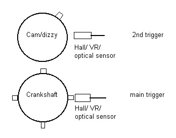
Hope this helps anybody else who's looking, as it took me quite some time to sort through all the info that is posted, and there is loads of the stuff.
GTS1000, FZR1000 & Thunderace crankshafts
Sun 17 Feb 2008 Filed in: MicroSquirt
Finally pulled the GTS1000 crankcase from a gash bottom end, and it's a surprise of sorts. Thought I had spotted four pits in the GTS crank, that are used for crank position sensing, and there are.

and compared to the Thunderace and the FZR1000 (right) there are some significant differences. The Thunderace and FZR are both 8-1 tooth (almost), the missing tooth or reference position is the single milled slot as opposed to the seven part drillings. No wonder the Thunderace project wouldn't fire using the GTS1000 ECU.
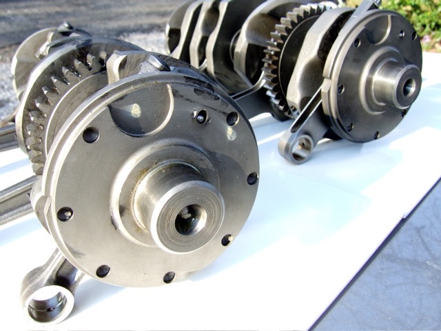
Looks like I could mod the crank, but I think I will end up using a new ECU. The MicroSquirt is small, looks good and is a fair price too.
Go to http://www.microsquirt.com for more info,
and compared to the Thunderace and the FZR1000 (right) there are some significant differences. The Thunderace and FZR are both 8-1 tooth (almost), the missing tooth or reference position is the single milled slot as opposed to the seven part drillings. No wonder the Thunderace project wouldn't fire using the GTS1000 ECU.
Looks like I could mod the crank, but I think I will end up using a new ECU. The MicroSquirt is small, looks good and is a fair price too.
Go to http://www.microsquirt.com for more info,
GTS1000 replacement fuel filter
Sat 02 Feb 2008 Filed in: GTS1000 Fuel
GTS1000 fuel filters are expensive over here, and not that cheap in Europe. Last time I looked on a European site they were close on €70 each. Now you are supposed to change them every two years or 24000 miles, so I am about due one. Apparently, in the UK they were £78 two years ago, and I wasn't going to pay that much to Yamaha for a £2 part, so I started looking for a pattern replacement. First you need the dimensions of the old one and although I have two bikes, I really couldn't be bothered to remove the plastic just to do the research and then bolt it back for the commute to work, besides it was cold and wet outside.
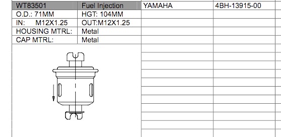
Fuel filter dimensions, with Yamaha part reference
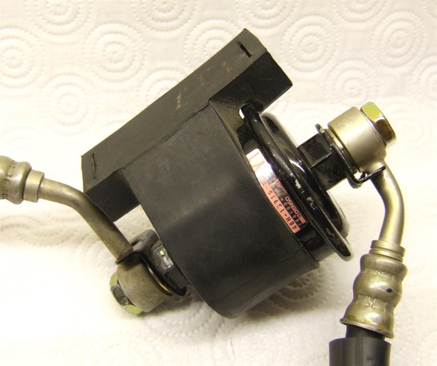
OEM fuel filter in rubber mounting cradle.
Problem is this filter is pretty unique, and after looking at several other reference documents, I only ever found a slightly longer version, and so it seems did others. In the USA they quote a Purofilter F44661, but in the UK this number is no use. A slightly longer version was made, at 125mm overall, that was fitted to several Japanese cars circa 1995 and later, so I looked for some cross references to this unit and found these numbers.
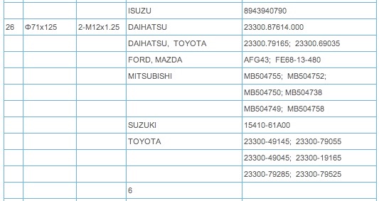
Vehicle cross references above with another version I found below whilst searching for later cross references.
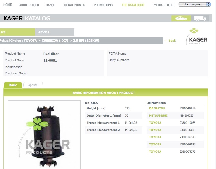
However this guy below was the winner, and I ordered one from Japtec in the UK to check it out. A few days later it arrived.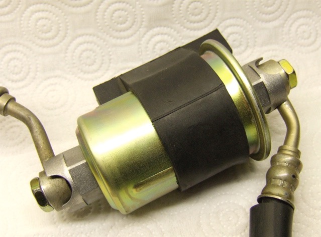
I ended up with a universal version, Solid Ace M303020, which is marginally longer than the original, and it fits under the plastic too. Not bad for a couple of days work, and cheap as chips too. I'd love to tell you how much, but it would embarrass Yamaha UK, suffice to say it's sub £10.
Fuel filter dimensions, with Yamaha part reference
OEM fuel filter in rubber mounting cradle.
Problem is this filter is pretty unique, and after looking at several other reference documents, I only ever found a slightly longer version, and so it seems did others. In the USA they quote a Purofilter F44661, but in the UK this number is no use. A slightly longer version was made, at 125mm overall, that was fitted to several Japanese cars circa 1995 and later, so I looked for some cross references to this unit and found these numbers.
Vehicle cross references above with another version I found below whilst searching for later cross references.
However this guy below was the winner, and I ordered one from Japtec in the UK to check it out. A few days later it arrived.
I ended up with a universal version, Solid Ace M303020, which is marginally longer than the original, and it fits under the plastic too. Not bad for a couple of days work, and cheap as chips too. I'd love to tell you how much, but it would embarrass Yamaha UK, suffice to say it's sub £10.
GTS1000 Fuel Pump
Sat 02 Feb 2008 Filed in: GTS1000 Fuel
Finally got my Broadband up and running, thank you local BT OpenReach engineer, and TalkTalk for not listening (faulty LLU equipment not the phone line)
I have seen a couple of GTS1000s with dead fuel pumps, only clue is the 15A fuse keeps blowing under the seat. This fuse feeds the fuel pump, fuel injectors and also the ECU. If you get dried up fuel deposits in your pump, because you've left stale fuel in there for a few years, the pump motor will stall and the fuse will blow. It is possible to tease the pump apart, as it has an annular crimping detail, but it's not ideal and in all honesty is probably beyond most DIYers comfort levels. Of course you could get a pump from Yamaha, but they only sell the complete pump assembly, and by then you'd be down several hundred pounds, last time I looked it was six of them!
What I needed to find for a couple of folks local to me was a cheaper alternative, and fortunately I had an OEM pump assembly from last years 2007 Treffen in Germany, provided by DrGTS from Denmark, when a UK guys tank went porous, and we borrowed the complete set up from his display exhibit. The original unit is a Denso, and some trawling around on the net, I located a couple of possibles. Quick search on eBay for cross referenced universal versions located a couple in the USA. Anyway, after a few weeks the sample pump arrived an AC Delco unit, suitable for a Honda Accord circa 1995, and the pictures speak for themselves.
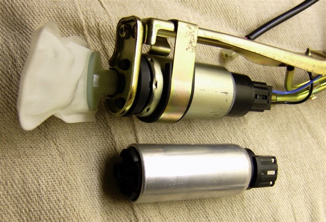
OEM Fuel Pump Assy with alternative unit
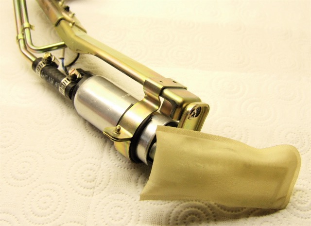
Alternative unit fitted in OEM fuel pump assy, plugs straight in
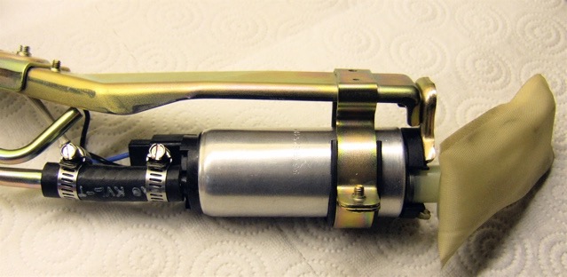
Close up of AC Delco EP482
I have seen a couple of GTS1000s with dead fuel pumps, only clue is the 15A fuse keeps blowing under the seat. This fuse feeds the fuel pump, fuel injectors and also the ECU. If you get dried up fuel deposits in your pump, because you've left stale fuel in there for a few years, the pump motor will stall and the fuse will blow. It is possible to tease the pump apart, as it has an annular crimping detail, but it's not ideal and in all honesty is probably beyond most DIYers comfort levels. Of course you could get a pump from Yamaha, but they only sell the complete pump assembly, and by then you'd be down several hundred pounds, last time I looked it was six of them!
What I needed to find for a couple of folks local to me was a cheaper alternative, and fortunately I had an OEM pump assembly from last years 2007 Treffen in Germany, provided by DrGTS from Denmark, when a UK guys tank went porous, and we borrowed the complete set up from his display exhibit. The original unit is a Denso, and some trawling around on the net, I located a couple of possibles. Quick search on eBay for cross referenced universal versions located a couple in the USA. Anyway, after a few weeks the sample pump arrived an AC Delco unit, suitable for a Honda Accord circa 1995, and the pictures speak for themselves.
OEM Fuel Pump Assy with alternative unit
Alternative unit fitted in OEM fuel pump assy, plugs straight in
Close up of AC Delco EP482
GTS1000 HID Headlight Conversion
Sat 18 Aug 2007 Filed in: GTS1000 Electrical
My bike was a Swiss model originally, which was fitted with a single H4, Hi/Lo bulb, so I changed it for a UK spec headlight which came with a split reflector design, comprising of a H4 Hi/Lo Beam (Main/Dip) section and a H3 Hi Beam (Main) section.
The only issue was the lighting was poor. At moderate speeds on a country lane, you’d drive on Lo or dip beam and have your finger on the flash button, as you accelerated out of the corners or braked into them, just to light up enough road...something had to be done. I needed to upgrade the lighting, and first choice is better bulbs. I did try a 100/80W unit, but although better, things got a little too warm. Then I read about HIDs, 3x the light output for 2/3rds the power, so a 55W bulb was replaced by a 35W unit. The way they work is they use a step up unit to create high (kV) voltage and use an arc process to create the light. As they don’t rely on heating a coil of wire, generating heat and a small amount of light they are more efficient.
I looked at acquiring some HIDs in the UK, but they were way top heavy, so I looked elsewhere, good ‘ol China c/o eBay, and noted I’d need a H4 & H3 set up, which I duly ordered and eagerly awaited their arrival, as I wanted to fit them before the 2007 Treffen.
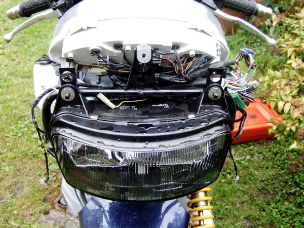
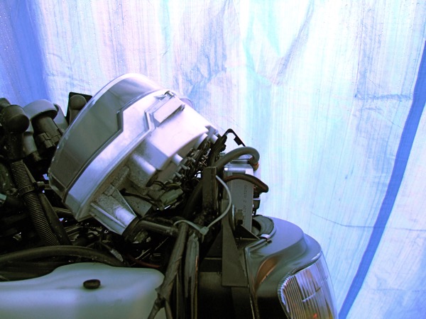
When they arrived, I whipped off the sidepanels and front fairing, and investigated a place to put them. The only problem it was chucking it down with rain, so I built a makeshift tent, using a leftover climbing rope, and a tarpaulin.
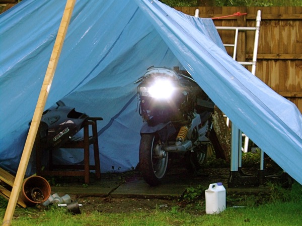
Above, GTS1000 in a makeshift tent, very wet outside, but HIDs working, and that’s just Lo or dip beam, plus I am not looking at it!
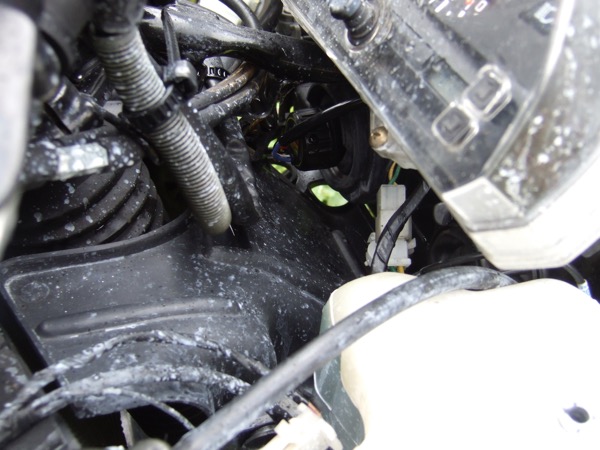
Looking at the space available, couldn’t really fit them around the steering column. The stains are from blowing anti-freeze, due to a faulty coolant reservoir cap rubber.
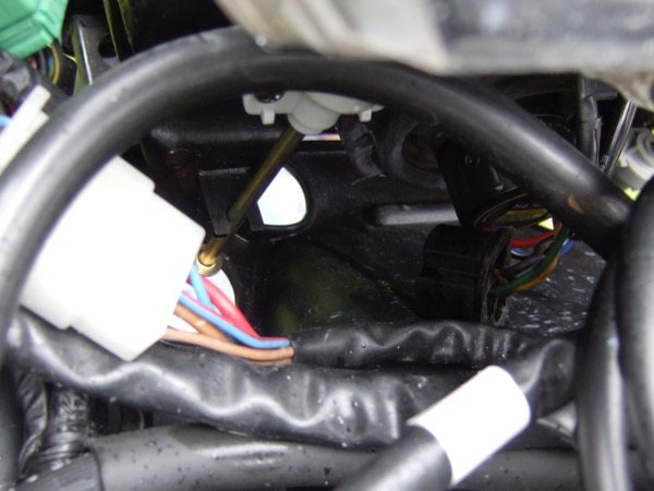
Neither was the space under the headlight any good, pictured above, but the area above the headlight showed the most promise, pictured below.
So that’s where the igniters went...
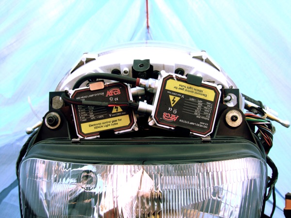
... and you could still get the front fairing cowl on...
Job well done, and a lot brighter.
The only issue was the lighting was poor. At moderate speeds on a country lane, you’d drive on Lo or dip beam and have your finger on the flash button, as you accelerated out of the corners or braked into them, just to light up enough road...something had to be done. I needed to upgrade the lighting, and first choice is better bulbs. I did try a 100/80W unit, but although better, things got a little too warm. Then I read about HIDs, 3x the light output for 2/3rds the power, so a 55W bulb was replaced by a 35W unit. The way they work is they use a step up unit to create high (kV) voltage and use an arc process to create the light. As they don’t rely on heating a coil of wire, generating heat and a small amount of light they are more efficient.
I looked at acquiring some HIDs in the UK, but they were way top heavy, so I looked elsewhere, good ‘ol China c/o eBay, and noted I’d need a H4 & H3 set up, which I duly ordered and eagerly awaited their arrival, as I wanted to fit them before the 2007 Treffen.
When they arrived, I whipped off the sidepanels and front fairing, and investigated a place to put them. The only problem it was chucking it down with rain, so I built a makeshift tent, using a leftover climbing rope, and a tarpaulin.
Above, GTS1000 in a makeshift tent, very wet outside, but HIDs working, and that’s just Lo or dip beam, plus I am not looking at it!
Looking at the space available, couldn’t really fit them around the steering column. The stains are from blowing anti-freeze, due to a faulty coolant reservoir cap rubber.
Neither was the space under the headlight any good, pictured above, but the area above the headlight showed the most promise, pictured below.
So that’s where the igniters went...
... and you could still get the front fairing cowl on...
Job well done, and a lot brighter.
GTS1000 air filter modifications
Sat 21 Apr 2007 Filed in: GTS1000 Air Filter
I was tinkering with the air filters the other day, and although I had a set of pattern replacements, i thought it was about time I made some reticulated foam ones. I ordered some foam from the bike wholesalers, but the RamAir samples were just too narrow to cover the filter completely.
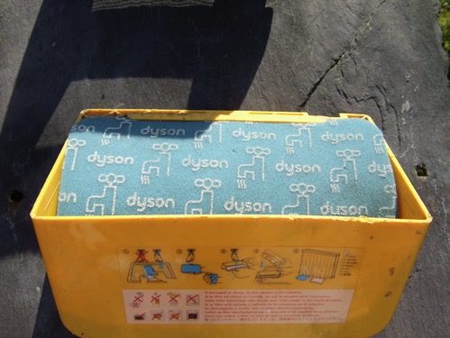
I had an newish Dyson DC11 lying around, which incidentally is junk from a design point of view, and I am not going there, but inside there happen to be rectangular pieces of good quality reticulated foam...and when the shops are shut.

Unfortunately, you can only buy the foam complete with the hard plastic external casing, but if you've got a DC11 it won't all be wasted.
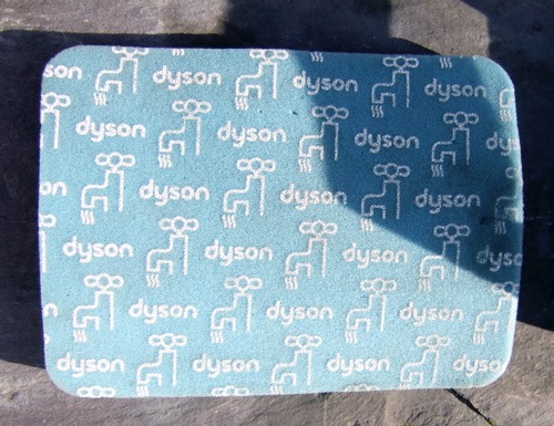
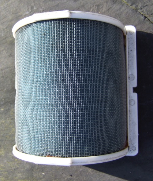
Pull out the foam from the Dyson filter housing, and don't forget you'll need two of them. They cost £20 for two, and all you do is remove the OEM paper pleating from the GTS1000 filters, so you are just left with the two plain gauze screens. It can be quite fiddly, but needle nosed pliers will speed things up.
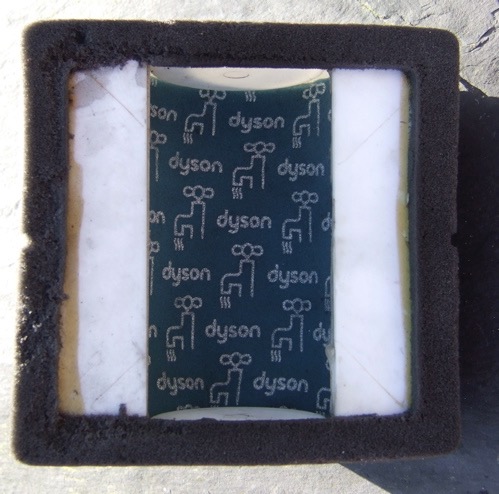
Fold the DC11 foam in the middle and post it home through the slot, and tease the foam into the corners, and bingo.
I had an newish Dyson DC11 lying around, which incidentally is junk from a design point of view, and I am not going there, but inside there happen to be rectangular pieces of good quality reticulated foam...and when the shops are shut.
Unfortunately, you can only buy the foam complete with the hard plastic external casing, but if you've got a DC11 it won't all be wasted.
Pull out the foam from the Dyson filter housing, and don't forget you'll need two of them. They cost £20 for two, and all you do is remove the OEM paper pleating from the GTS1000 filters, so you are just left with the two plain gauze screens. It can be quite fiddly, but needle nosed pliers will speed things up.
Fold the DC11 foam in the middle and post it home through the slot, and tease the foam into the corners, and bingo.
ABS Pump Stripdown
Mon 12 Feb 2007 Filed in: GTS1000 ABS
Yamaha GTS1000 ABS pump units are very expensive, and apparently are similar to the FJ1100 units. Info on stripping them down is available on the internet, but I started from a unit that had been bought as bits, and stored in the loft. The sole reason for stripping the unit down was to investigate the O ring sizes, so that the units could be serviced like any other brake part, rather than be replaced. Read More...
Odometer, tripmeter conversion
Sat 09 Dec 2006 Filed in: GTS1000 Electrical
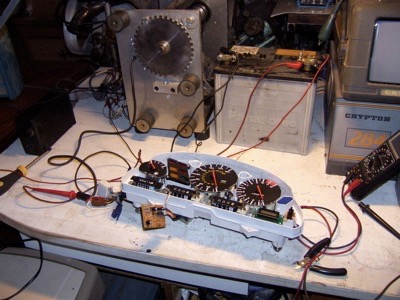
Whilst looking at the instrument panel and the speedo assembly last time, I noticed the board had some jumpers missing, which related to the external divisor pins for the IC that converts the front wheel pulses into a speedo signal. These were also used to feed the electric motors that power the odometer and tripmeter assembly. I wondered whether this was the kilometer or mile conversion area, or whether it was mechanical via the gearing.
I managed to get hold of a kilometer unit, and it turns out it is electronic after all.
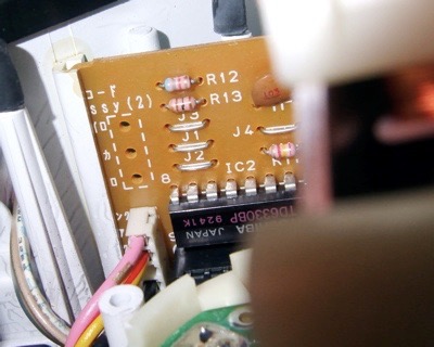
If you compare the previous blog image with this board, you'll notice that the jumpers J1 & J2 are bridged, whereas in the mile version they are not used.

I'll be testing this out when I run the mile unit up on the fuel injection rig, the easiest way is to spin up the sensor and see how far the tripmeter travels in say two minutes, bridge the J1 & J2 connections, reset the tripmeter and see if the distance is 1.6x greater for the same time & rotation speed.
Here's hoping it will, 'cos I've got an import too, that reads distances in kilometers, and although I can do the maths, it'll be good to see distance travelled match the road signs. for a change
Speedo fix after removing ABS ECU
Tue 14 Nov 2006 Filed in: GTS1000 Electrical
A few folks out there with a Yamaha GTS1000A have removed their ABS units, and then later discovered their speedometer does not work. Not surprising when the speedo gets it's info from the ABS ECU on these bikes, but there are genuine non ABS bikes out there too. So what was doing it.
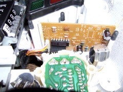
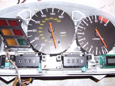
A little investigation in the wiring loom diagrams for both models suggests there is a difference at the speedometer area, so I removed the instrument cluster from a donor bike, a UK spec 4BH GTS1000A. Surprisingly, there was an undocumented sixway connector that interfaced with the speedo area, although on the ABS unit I was looking at, only four of the sixway connector pins were populated. This sixway connector fed the circuit board below, which I assumed processed the pulses to create a speedo reading.
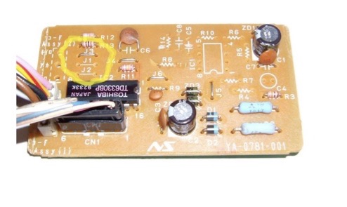
This is the board that is different, as the speedo stepper motor only has three inputs, this board has four inputs potentially, and has several outputs. One to odometer, one to the trip meter via the black horizontal connector, and a pink output to the speedo from the white vertical element.The chip is a Toshiba TD6330BP, a generic stepper motor driver, with optional external divisor inputs and outputs, as well as Schmitt circuitry, which is useful for processing inductive pickups.
After looking at the circuit board and the fiveway white strain block, I noticed the middle pin was not used and noted there was Assy(1) and Assy(2) markings plus a lot of the board is not populated with electronic components. As the speedo only has and needs three inputs, a 12V feed, a 12V ground and a pink input from the board, and this leads to the white vertical element on the left of the board, which ony uses four out of five potential solder areas. The only available space for a potential signal ground from the front wheel sensor would bridge to the board ground. Reading the specs of the chip, the ground plane is well isolated, so I thought I would feed the missing part of the inductive signal pulse into this, with the existing yellow/red wire feed being the other.
First of all, I needed to generate a pulse, fortunately I had a homemade variable speed fuel injection rig that had a single toothed wheel matched to a two wire inductive sensor, just like the Yamaha front wheel sensor...sure there wasn't a lot of teeth on it, but it would spin up to 11000 rpm, so I should get a signal. After hooking a 12V battery up to a charger...(don't you just love it when you want to do something and stupid things get in the way)...to create my power feeds, which incidentally are brown/black in large white connector block becomes +12V, black/brown in the blue connector is ground, and one feed from the inductive pickup is fixed to the yellow/red wire in the large white block , and the other makes contact with the black/brown in the blue plug.
Switch on the motor and yippee it works. Switch it off and it stops!
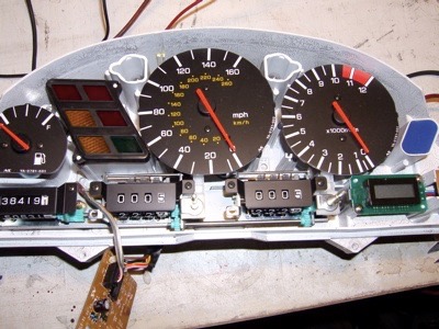
Notice how the odometer and trip meters have moved on.
So if you plan on getting rid of the ABS system on a Yamaha GTS1000A and want to get your speedo to work, you will need to jump the yellow/red wire in the ABS ECU plug to the white wire from the wheel speed sensor, and break into the loom to pick up the black/brown ground wire and splice the black wire from the front wheel sensor into it. Might be best to do this at the small white plug connector near the top of the left hand side Omega Chassis rail that connects the front wheel sensor into the main loom.
A little investigation in the wiring loom diagrams for both models suggests there is a difference at the speedometer area, so I removed the instrument cluster from a donor bike, a UK spec 4BH GTS1000A. Surprisingly, there was an undocumented sixway connector that interfaced with the speedo area, although on the ABS unit I was looking at, only four of the sixway connector pins were populated. This sixway connector fed the circuit board below, which I assumed processed the pulses to create a speedo reading.
This is the board that is different, as the speedo stepper motor only has three inputs, this board has four inputs potentially, and has several outputs. One to odometer, one to the trip meter via the black horizontal connector, and a pink output to the speedo from the white vertical element.The chip is a Toshiba TD6330BP, a generic stepper motor driver, with optional external divisor inputs and outputs, as well as Schmitt circuitry, which is useful for processing inductive pickups.
After looking at the circuit board and the fiveway white strain block, I noticed the middle pin was not used and noted there was Assy(1) and Assy(2) markings plus a lot of the board is not populated with electronic components. As the speedo only has and needs three inputs, a 12V feed, a 12V ground and a pink input from the board, and this leads to the white vertical element on the left of the board, which ony uses four out of five potential solder areas. The only available space for a potential signal ground from the front wheel sensor would bridge to the board ground. Reading the specs of the chip, the ground plane is well isolated, so I thought I would feed the missing part of the inductive signal pulse into this, with the existing yellow/red wire feed being the other.
First of all, I needed to generate a pulse, fortunately I had a homemade variable speed fuel injection rig that had a single toothed wheel matched to a two wire inductive sensor, just like the Yamaha front wheel sensor...sure there wasn't a lot of teeth on it, but it would spin up to 11000 rpm, so I should get a signal. After hooking a 12V battery up to a charger...(don't you just love it when you want to do something and stupid things get in the way)...to create my power feeds, which incidentally are brown/black in large white connector block becomes +12V, black/brown in the blue connector is ground, and one feed from the inductive pickup is fixed to the yellow/red wire in the large white block , and the other makes contact with the black/brown in the blue plug.
Switch on the motor and yippee it works. Switch it off and it stops!
Notice how the odometer and trip meters have moved on.
So if you plan on getting rid of the ABS system on a Yamaha GTS1000A and want to get your speedo to work, you will need to jump the yellow/red wire in the ABS ECU plug to the white wire from the wheel speed sensor, and break into the loom to pick up the black/brown ground wire and splice the black wire from the front wheel sensor into it. Might be best to do this at the small white plug connector near the top of the left hand side Omega Chassis rail that connects the front wheel sensor into the main loom.
Finally got some real horsepower
Sat 14 Oct 2006 Filed in: GTS1000 Horsepower
New improved GTS1000A... a SuperSportsTourer is born! How to tune a GTS...
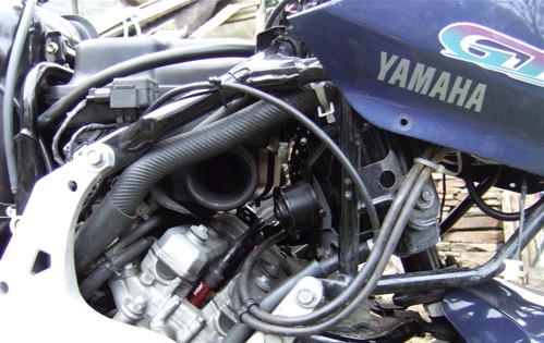
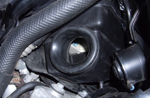
make some bigger holes in the airbox,
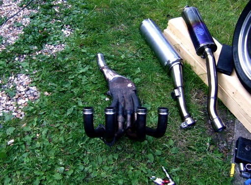
fit a less restrictive exhaust & silencer
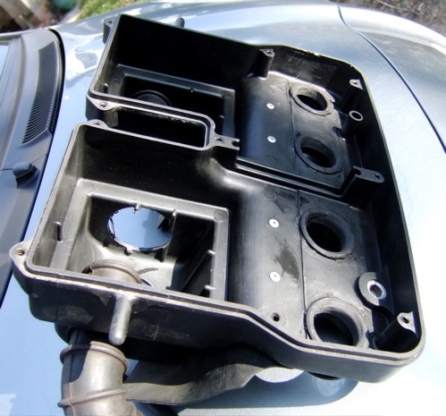
and then modify the internal inlet snorkels (early airbox shown, extra oversized external holes inside the airbox can be seen). The internal snorkels are removed at the base and radiused with a Dremel or similar.
and life is a big gas

Notice the start of a bell shaped curve (red one)...yippee... just needs a fuelling tweak and it'll be awesome vs standard!
Peak horsepower now at 113 RWHP, or around 125 crankshaft (DIN) HP estimated, but the real surprise is there are no losses compared to standard, and the average horsepower is 22% greater than before, which translates into 22% more acceleration, and the gains are huge, especially from 7000 rpm.
Just lost a major criticism of the GTS having poor top end power, compared to it's FZR engined cousins, and the best bit is I have seen 118 horsepower, but I couldn't run the bike like that...not yet anyway..
I'll dig out the curve for you naysayers.
make some bigger holes in the airbox,
fit a less restrictive exhaust & silencer
and then modify the internal inlet snorkels (early airbox shown, extra oversized external holes inside the airbox can be seen). The internal snorkels are removed at the base and radiused with a Dremel or similar.
and life is a big gas
Notice the start of a bell shaped curve (red one)...yippee... just needs a fuelling tweak and it'll be awesome vs standard!
Peak horsepower now at 113 RWHP, or around 125 crankshaft (DIN) HP estimated, but the real surprise is there are no losses compared to standard, and the average horsepower is 22% greater than before, which translates into 22% more acceleration, and the gains are huge, especially from 7000 rpm.
Just lost a major criticism of the GTS having poor top end power, compared to it's FZR engined cousins, and the best bit is I have seen 118 horsepower, but I couldn't run the bike like that...not yet anyway..
I'll dig out the curve for you naysayers.
GTS1000 SuperSports Tourer
Sat 08 Jul 2006 Filed in: GTS1000 Horsepower
What a difference a few hours make, and the red curve was the finished result.
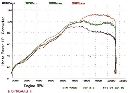
Earlier in the morning on the dyno, I was at the green curve stage, come the afternoon I was sitting pretty on the red curve, and when you compare the gains from each improvement, you can see a GTS responds well to modification. If you look at the standard curve and where I am now, there are virtually no losses, and huge gains, between 22-36 hp more than standard, and no camshafts, engine mods or porting has been done to date. Talk about free horsepower.
Earlier in the morning on the dyno, I was at the green curve stage, come the afternoon I was sitting pretty on the red curve, and when you compare the gains from each improvement, you can see a GTS responds well to modification. If you look at the standard curve and where I am now, there are virtually no losses, and huge gains, between 22-36 hp more than standard, and no camshafts, engine mods or porting has been done to date. Talk about free horsepower.
