IGNITION UPDATE
15 August 2014
Imfsoft have revised their range of programmable ignition modules. The motorcycle derived unit I was using before, is no longer made, and more importantly the software has been modified to use a multi tooth wheel. This impacts the original timing cover I had made, as the two sensor version that used a simple trigger wheel is no longer supported.

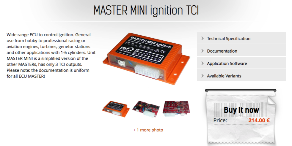
This means in the future there will be only one version of the timing cover, that will take one sensor, and both the ignition and injection systems will use the 12-1 trigger wheel I have developed. It is possible to use this cheaper Imfsoft for injection with some compromises, but if this is your intention, than I recommend the slightly more expensive 4TCI version at €266,00. This will drive two ignition and two injection channels.
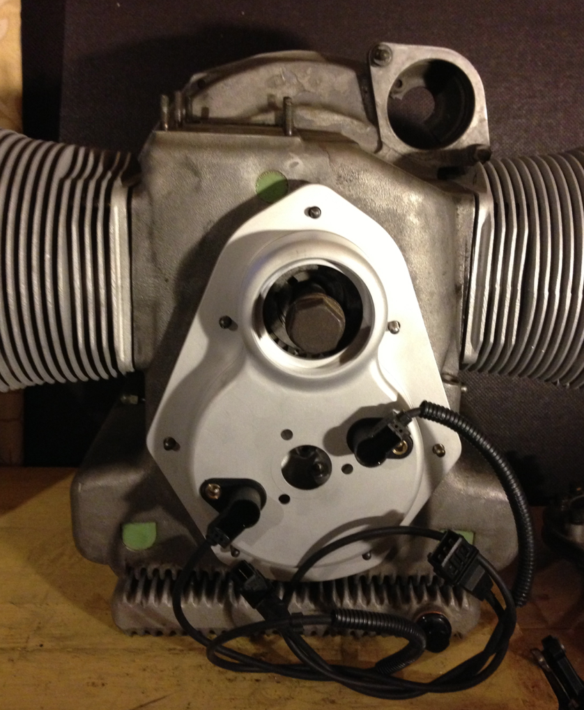
The timing cover on the left with two sensor holes will be replaced by the type on the right, which only has one sensor hole.
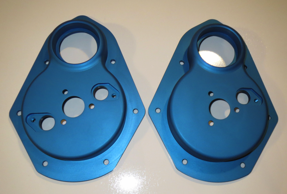

For anybody that has bought the two sensor version, and not bought an Imfsoft Direct Ignition TCI already, I will be offering a oil tight aluminium part, that will seal the surplus hole. In the future, they will be one hole or no hole versions only, and the one hole version will work for all types of ignition modules, that is MicroSquirt, Megasquirt or Imfsoft units.
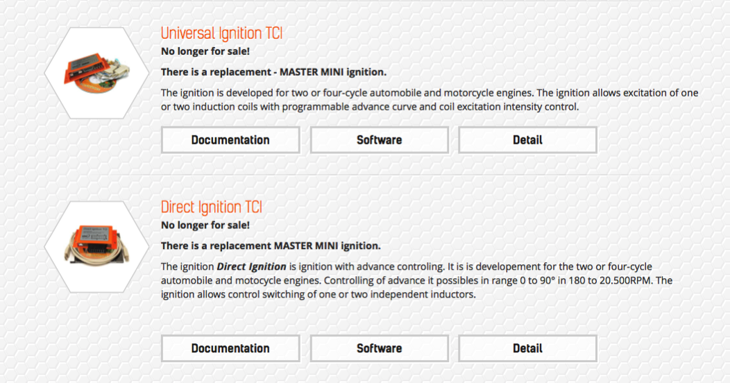
Link to Imfsoft MASTER MINI Ignition TCI

PANHARD IGNITION An Introduction
12 May 2012
Original Panhard ignition systems are distributor based usually incorporating a vacuum advance and sometimes this is combined with the usual centrifugal weight advance system. The problem is these systems were designed in the 1950's, fitted to cars in the 1960's and catered for the fuel of the day. Modern fuels are slightly different, so the original advance values are not a good match. Nearly all air cooled flat twin Panhard engines will benefit from reduced ignition advance, but that is not the real issue.
it seems the distributors in most cars I see are the original worn units, and surprisingly the wear increases the advance levels even further. Typically, a seemingly good distributor can have 23º advance on the vacuum side, with an additional 28º on the centrifugal side. If you dial in say the static advance of 21-31º of the Tigre engine, you can get values close to 70º advance which is double what you need.
After talking to folks at Almen, where the 2013 International Panhard Meeting was held, I learned that even the Hampe system was not as good as it could be either, because the twin contact breaker system was a pig to set up. Another man mentioned that even with a programmable electronic ignition in his distributor, he was seeing a 2-4º variation between cylinders, when using a strobe, which was down to distributor cam lobe wear.
However, most of the variation is due to the backlash & free play in the standard system, because the crank gear drives the cam (chevron gears), the cam gear drives the oil pump (helical), the oil pump gear drives the breather shaft (straight), then there is a slotted drive to the breather shaft, and another joint on a roll pin, plus the slotted drive to the distributor. the distributor clamp is so poor, that the whole assembly wobbles, so you can see the precision is just not there.
As part of my engine developments, I wanted to incorporate a modern ignition system, and I looked at all the options. I have made a few prototypes, but they were all distributor based, so are flawed before they start. Modern cars use the crankshaft pulley, camshaft pulley & flywheel, because they are precise locations, and although I did have a toothed wheel idea for the front pulley, at one stage, and was convinced at the time this was a good direction. So much so, I even built a test rig using laser cut trigger wheels, but when I got the quotes back for making these parts it needed a rethink, because it wasn't economic and ultimately I needed a cam based system for sequential ignition timing or possible fuel injection further down the line.
After looking at the separate developments, crankshaft oil seal upgrade, cam based triggering and combining them, it was possible that making a new front cover would be the best solution, because one part would "kill two birds". However this is quite a large component, that has to interface to quite a few existing parts, like the cowling gaskets, metal plate and the existing oil light switch, all of which would mean quite a bit of development to get it right. I roughed out the shape in CAD, and although the basic size was complete, the positioning of the sensors or the ignition system had not been decided.
So now the big question was what type of triggering mechanism or ignition should I use? As my motorcycles used VR or inductive sensors, I looked at these first. The problem is they are a simple trigger, whose performance varies with speed & air gap. I had experienced problems with this using a MicroSquirt many years ago, and I decided to boost the performance using a cheap cobalt samarium magnet. This gave good low speed cranking performance, and great air gap & temperature tolerance, but at the time I couldn't buy the electrical connector for the Renault crank sensor part, so I started to look at other sensors fitted with 2 & 3 pin Junior Timer connectors, which are readily available.
Some of these sensors are inductive, some Hall effect, and some gear tooth Hall effect, and it was these latter types I looked at in more detail. Trouble is the cost of these parts varies hugely, so you can make a simple trigger, and then pay £100 for two sensors, which makes the whole system uneconomic. I needed to find a cheaper, readily available sensor, that offered good performance and wasn't too tall, that it would hit the fan or turbine.
Fortunately after four attempts, BMW, Citroen, Rover & Fiat, I found a good Opel/Vauxhall one. It is a gear tooth sensor, so it is directional, and has circuits in it that refine the signal for the ignition module, which makes for better signal processing & less signal interference.
It was also exposed to an oil in its original usage, so it was as close to perfect as I needed, even more so when I checked the sensing capabilities. Its low speed performance was excellent, they were under €10 each, and just about small enough. The sensitivity was so good, I could use a small socket set screw as the trigger, and it would reliably trigger throughout the designed speed range, 100-4000 rpm. Incidentally, a good starter normally turns the engine over at 200 rpm, and this sensor would trigger, switch on the ignition and spark at 7 rpm!
Next up was the ignition system, and the good news is the single trigger can work with a variety of good programmable systems out there, including the MicroSquirts & better still, as in cheaper, the Imfsoft Ignition from the Czech Republic. By using the camshaft, I could fool the system into sequential triggering, but only if I used two sensors, like the image below.
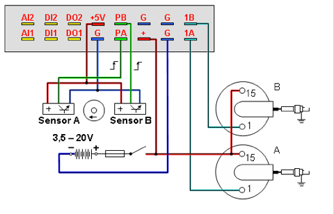
Their unit the €178,00 IgnitionTCI 6.1 can handle two extra analogue (A11 &A12) or digital inputs (D11 & D12), say temperature and MAP (manifold air pressure) as well as having a switchable curve, that allows the advance curve to be switched to another set of values if you trigger the input (D01). Potentially, you might use this as a knock sensor trip or even an over temperature event. Assuming you are using an aluminium camshaft gear, you can easily incorporate a modern cam based trigger wheel, and use a larger variety of programmable engine management systems. As I use two sensors on the camshaft, I can get sequential ignition timing, and do away with wasted spark, and this system has enough coil current headroom to fit two twin single fire coils to fire a twin plugged engine sequentially.
By now then, virtually all the pieces were in place to make a good first attempt, so 4 brave souls committed themselves to the cause, thank you Pierre, Dirk, Stefaan & Jean Paul, and I made 5 new timing covers.
I have to say the basic design, shown above, is a total success, and only needs a couple of refinements for series production. Obviously, there is quite a bit of machining time in this item, and being made from solid billet it will never be as cheap as a mass produced item, but the whole concept has been refined to make it a cost effective & the most flexible solution I can achieve, and this will form the basis of future engine developments from me.
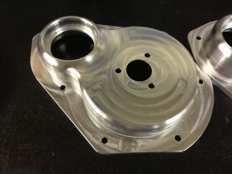
Below is the latest version of the aluminium timing cover, which has increased depth for the oil light switch, and a deeper crankshaft front seal aperture, which allows for simpler front pulley machining.
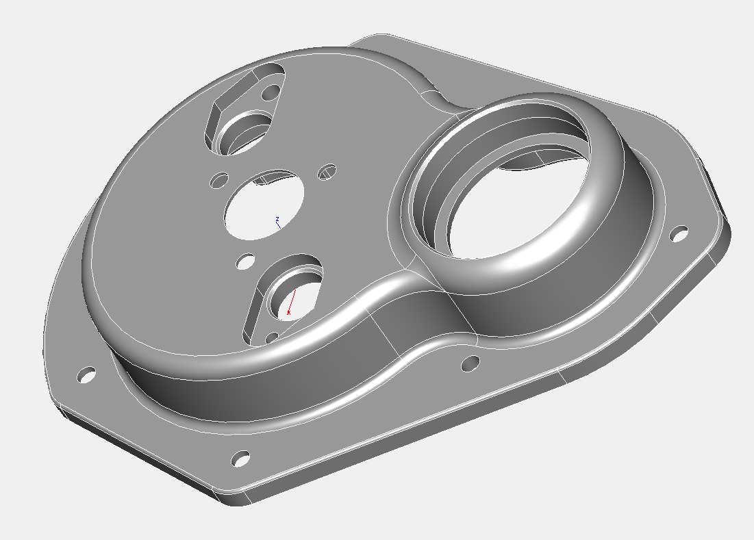
The machining process allows me to suppress the ignition sensor holes, so that no sensors, one sensor or two sensors can be incorporated into the cover depending on the type of ignition control the engine desires. Below is the latest CNC prototype, and this is the no sensor version, which is a simple replacement part for the pressed steel cover, which creates a modern front crankshaft oil upgrade solution.
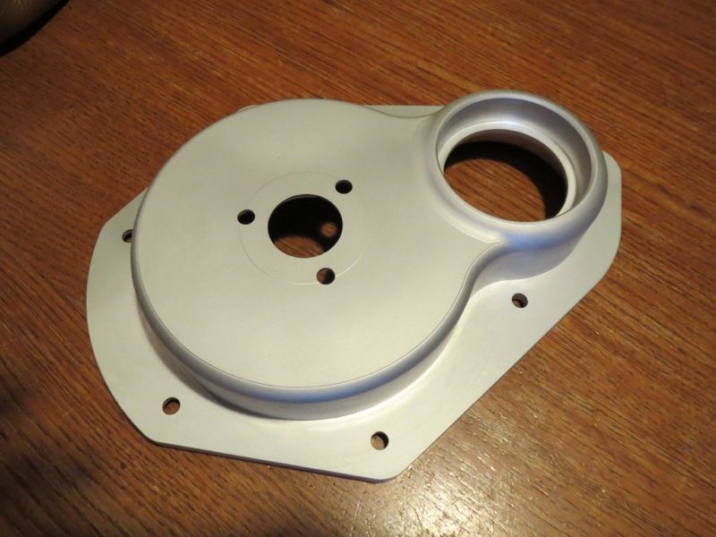
The part below hasn't been vapour blasted, but the one below has, and this is representative of the finish the final part will have.