May 2012
Panhard Dyno Rig
29/05/12 19:14 Filed in: Dyno
I am still waiting for pistons, so it’s time to refine the dyno rig that I will be using for testing the Panhard engines.
I was able to collect some new linkages from the laser cutters, and I fitted these Sunday. Unfortunately, the new links with revised centres, caused the chain to get too slack in the “wheel off the roller position”, so I looked at increasing the flywheel sprocket.
I did not want to change the chain, as the same chain will be used on the motorcycle engine, kart engine and Panhard rig. I could have lifted the Panhard engine rig upwards, but then I’d have to do the same for the kart rig, as this too is mounted on the top part of the wheel subframe.
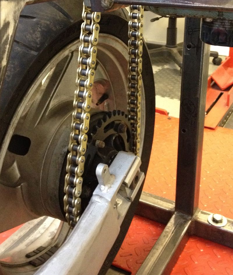
Today I managed to get a 19T 5/8” taper lock simplex sprocket, which increases the tooth count by one. However when I fitted it to the Panhard engine, there was too much chain tension, so by swapping out the linkages for a slightly longer version, I could just clear the tyre from the roller in the lift position, and also apply sufficient tension in the dyno test mode.
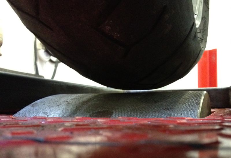
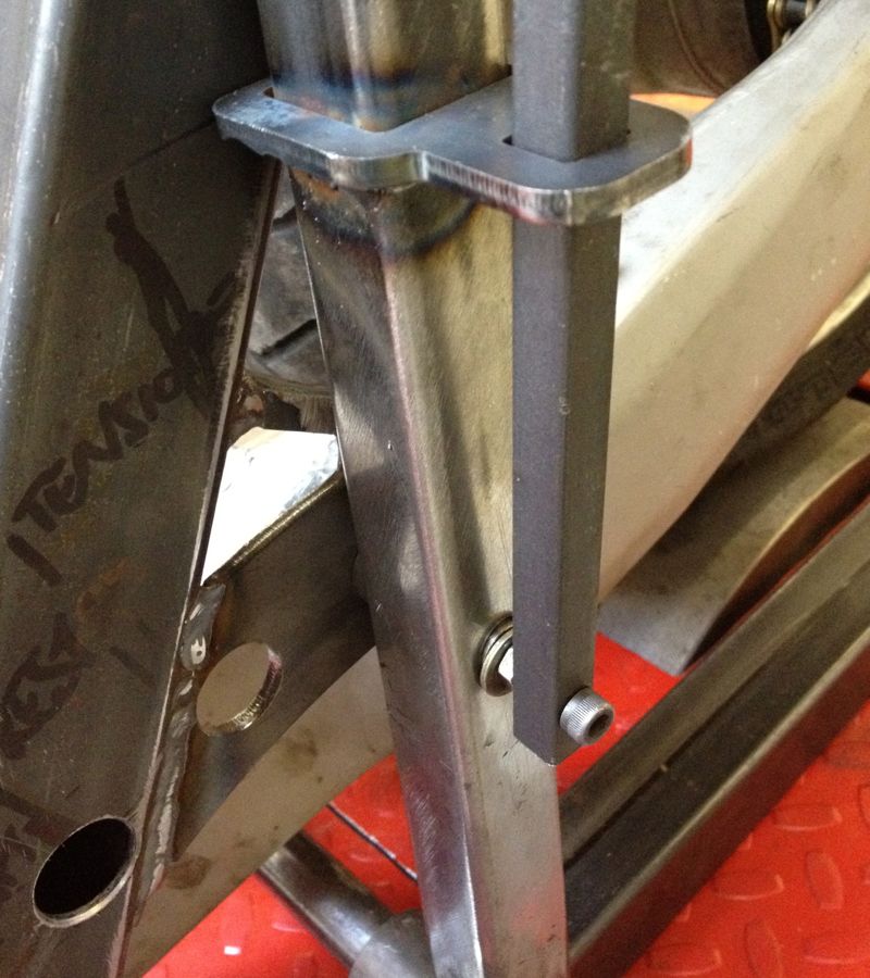
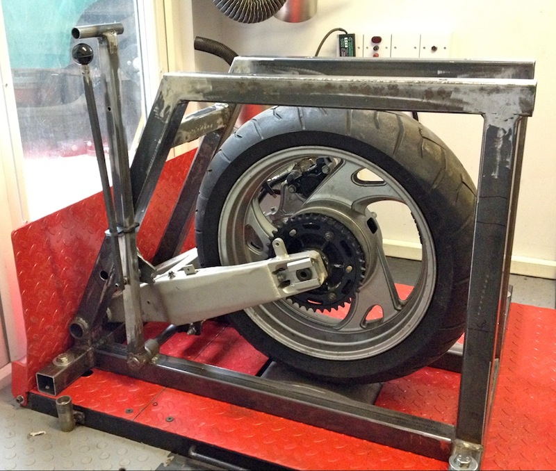
This is a close up of the lock mechanism, that loads the tyre on the roller and also holds the tyre clear of the roller, which is shown in the picture above. The tensioning mechanism pulls on the existing swinging arm dog bone connections, and the position is held via a locking pin, that engages within two holes. The hole in the box section was for an earlier version.
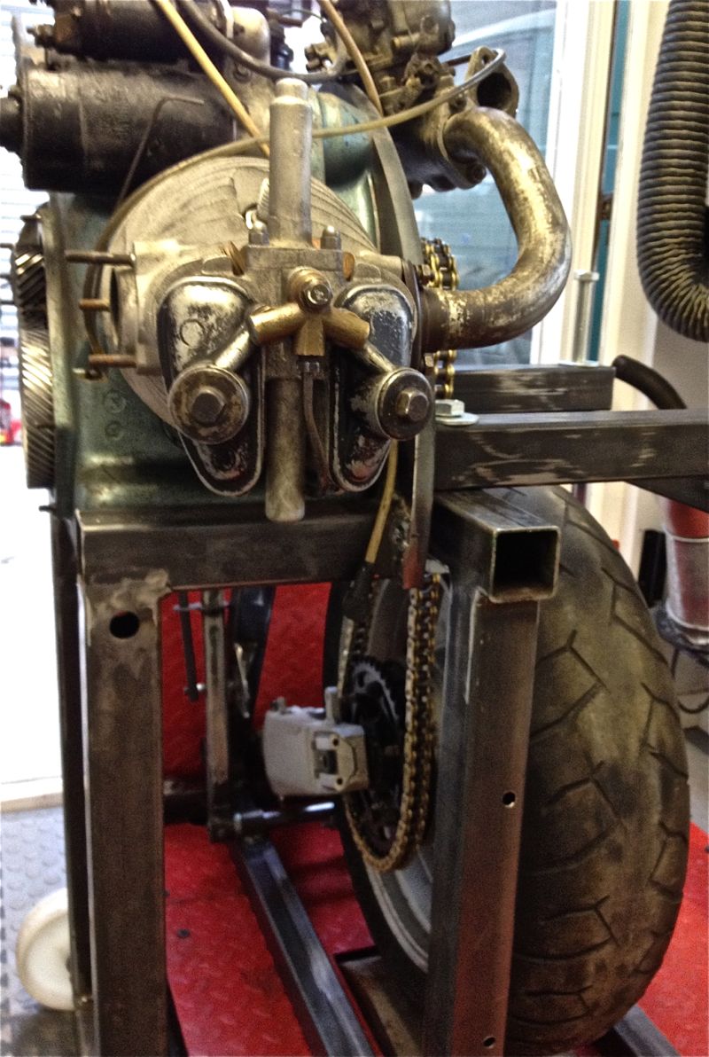
So just to recap, the Panhard engine directly drives the motorcycle wheel via a chain, which in turn spins the inertia roller when the tyre is tensioned into it.
I was able to collect some new linkages from the laser cutters, and I fitted these Sunday. Unfortunately, the new links with revised centres, caused the chain to get too slack in the “wheel off the roller position”, so I looked at increasing the flywheel sprocket.
I did not want to change the chain, as the same chain will be used on the motorcycle engine, kart engine and Panhard rig. I could have lifted the Panhard engine rig upwards, but then I’d have to do the same for the kart rig, as this too is mounted on the top part of the wheel subframe.
Today I managed to get a 19T 5/8” taper lock simplex sprocket, which increases the tooth count by one. However when I fitted it to the Panhard engine, there was too much chain tension, so by swapping out the linkages for a slightly longer version, I could just clear the tyre from the roller in the lift position, and also apply sufficient tension in the dyno test mode.
This is a close up of the lock mechanism, that loads the tyre on the roller and also holds the tyre clear of the roller, which is shown in the picture above. The tensioning mechanism pulls on the existing swinging arm dog bone connections, and the position is held via a locking pin, that engages within two holes. The hole in the box section was for an earlier version.
So just to recap, the Panhard engine directly drives the motorcycle wheel via a chain, which in turn spins the inertia roller when the tyre is tensioned into it.
Comments
Waiting for Panhard pistons
12/05/12 18:11 Filed in: Panhard Engine
Another couple of busy weeks at work, and a bit of metal from the laser cutters has arrived. The first batch of parts were for modding the engine dyno rig, which will be need to test the Panhard engines, and the second batch are for the Whatton boring bar adaptor plates to the Elliot mill bed.
Earlier I was going to make a bespoke centrifugal clutch to isolate the inertia roller from the crankshaft sprocket, but in the interests of simplicity, I decided to remove the turnbuckle that loaded the motorcycle wheel onto the inertia roller, and replace this with a quick release tensioning mechanism. This would allow me to manually unload the engine from the dyno roller for starting and also at the end of the dyno run, just like the centrifugal clutch would do, but without all the teething problems from a bespoke design.
I still have to make a chain tensioner, but the pictures below show the unloaded and loaded positions. The wheel is loaded by pulling the T handle to the right, and simultaneously pushing the ball ended lever inwards, which disengages a sprung loaded pin from a series of circular holes, and allows the tensioning lever to move to a new position. I created an even further stop to jack the wheel clear of the frame base, so that I can manoeuvre the rig around the workshop floor.
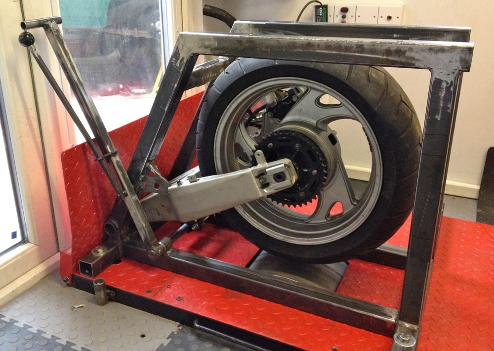
Hopefully tomorrow, I can bolt the Panhard engine up to it, explore the tensioning options, and try and draw something up for the laser cutter.
Earlier I was going to make a bespoke centrifugal clutch to isolate the inertia roller from the crankshaft sprocket, but in the interests of simplicity, I decided to remove the turnbuckle that loaded the motorcycle wheel onto the inertia roller, and replace this with a quick release tensioning mechanism. This would allow me to manually unload the engine from the dyno roller for starting and also at the end of the dyno run, just like the centrifugal clutch would do, but without all the teething problems from a bespoke design.
I still have to make a chain tensioner, but the pictures below show the unloaded and loaded positions. The wheel is loaded by pulling the T handle to the right, and simultaneously pushing the ball ended lever inwards, which disengages a sprung loaded pin from a series of circular holes, and allows the tensioning lever to move to a new position. I created an even further stop to jack the wheel clear of the frame base, so that I can manoeuvre the rig around the workshop floor.
Hopefully tomorrow, I can bolt the Panhard engine up to it, explore the tensioning options, and try and draw something up for the laser cutter.
