Panhard Ignition
Panhard Front Timing Cover, Revised again & updated
07/05/13 21:45
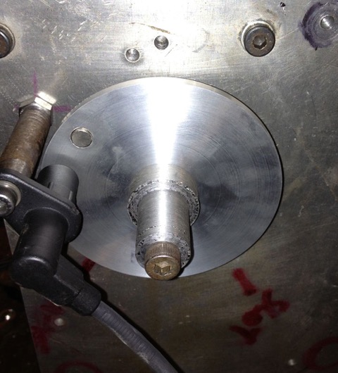
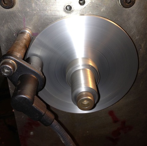
So I got the modded cover back tonight, and after testing the clearances at the oil light switch and the sensor to fan, I realised that the first batch need another tweak, but that’ll have to do for the next batch.
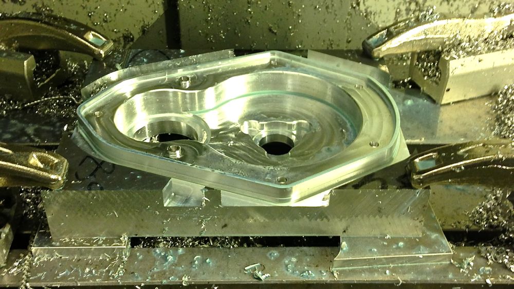
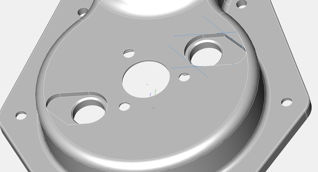
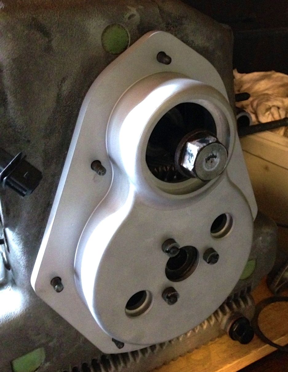
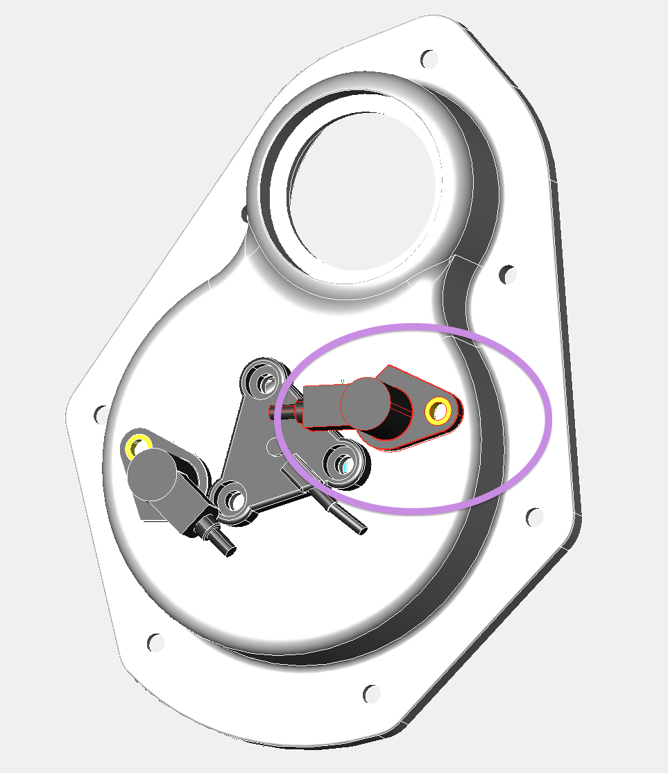
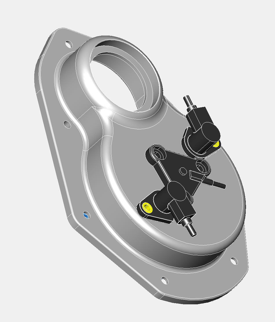
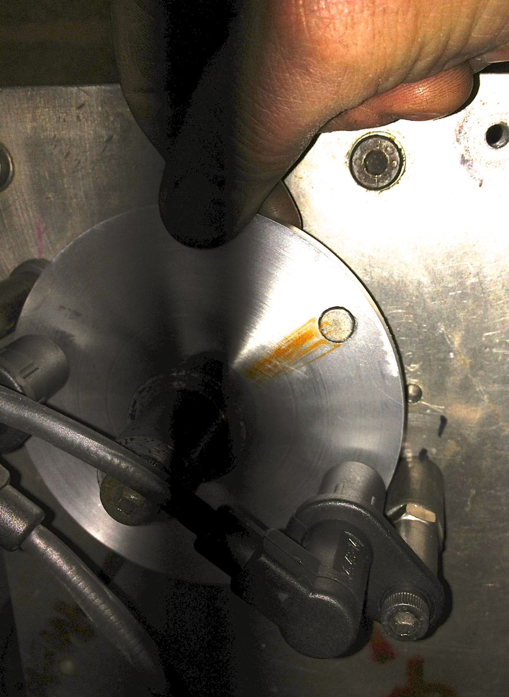
I have simplified the sensor through hole (pictured above), and recessed the sensor by another millimetre for this batch. The oil light internal depth is as far machined as I can go, and ideally needed another millimetre here, so I modded my oil light piston, essentially just making it shorter. Nothing is bolted down in the pictures, as I am just testing the fit, although I did use a multimeter to confirm the action of the oil light switch contacts.
Tomorrow, I’ll do a final test fit for the sensor body into the recessed area, and that’ll be that for this batch.
In the future I will tweak the design slightly, but that’ll be just for the oil light operation.
Comments
Panhard Front Timing Cover Sensor Fit & Update
05/05/13 18:59
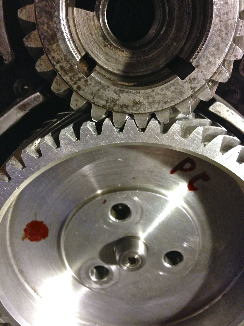
Last night I was sitting pretty, so to speak, but this morning I decided to fit the wooden blocks and springs to mount the front fan assembly and check the clearance on Brian’s engine. After torquing up the pulley centre bolt, I noticed a few millimetres of clearances, but on rotating the turbine or fan, it scraped the top of the sensor.
I have never seen a misshaped turbine before, so I tried several different ones I had lying around, and surprisingly they were all misshaped, with the resultant wobbling just catching the top of the sensor at some point, so obviously more clearance was needed.
I had two options change the sensor, or recess the sensor some more, and as all my work on the sensor was completed and it is a cost effective (aka cheap) solution with excellent sensitivity, I was reluctant to change the former. This meant recessing the sensor into the timing cover. As I looked at this, I thought I’d check the oil light function, and this too was just too tight a fit, such that the oil light would never illuminate, which isn’t a bad thing, but it isn’t how I intended things to operate.
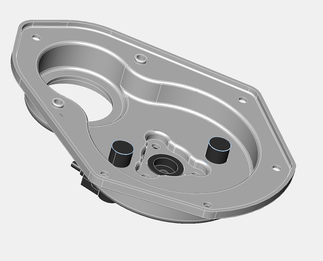
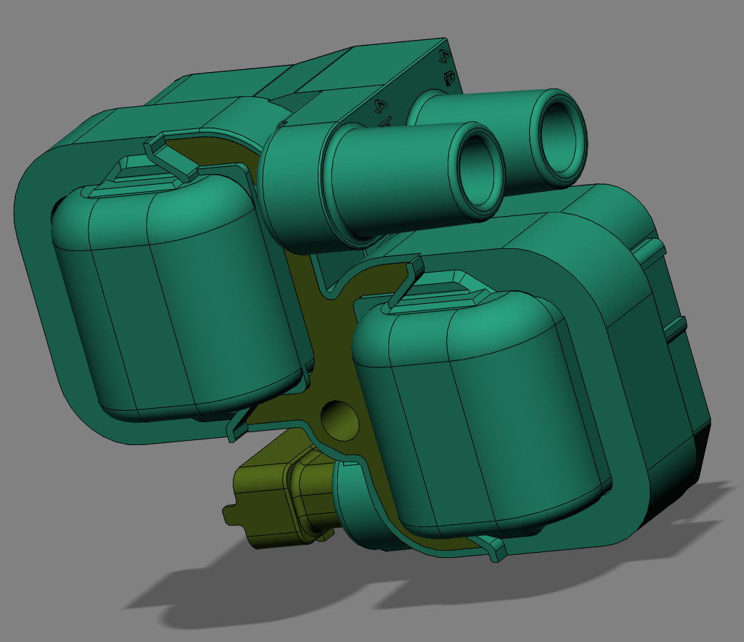
So a quick 3D tweak was in order, and this has been passed onto the 3D CNC fabricator. Slightly annoying for him, but better for us all. Oil light switch surface has been reduced in thickness (blue area) in the picture below, and below this the recessed area to add more sensor to turbine clearance. Not quite as elegant as I’d like, but it’ll do for now, and after testing there might be a slight refinement for the next batch.
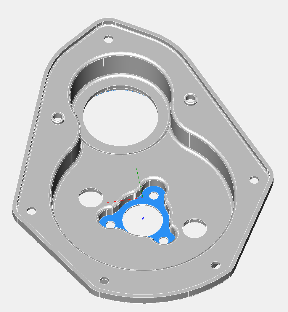
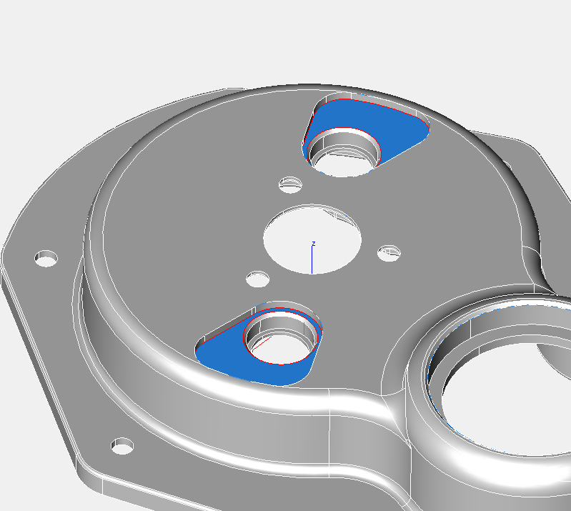
PS I thought I would weigh this part, and check the calculated weight in the CAD model versus the actual weight. The CAD model suggested 719 grams, but the actual weight was 723 grams, which is pretty close, and well within 1%. Incidentally, the standard part weighed around 530 grams, but this new timing cover is considerably thicker in places.
I have never seen a misshaped turbine before, so I tried several different ones I had lying around, and surprisingly they were all misshaped, with the resultant wobbling just catching the top of the sensor at some point, so obviously more clearance was needed.
I had two options change the sensor, or recess the sensor some more, and as all my work on the sensor was completed and it is a cost effective (aka cheap) solution with excellent sensitivity, I was reluctant to change the former. This meant recessing the sensor into the timing cover. As I looked at this, I thought I’d check the oil light function, and this too was just too tight a fit, such that the oil light would never illuminate, which isn’t a bad thing, but it isn’t how I intended things to operate.
So a quick 3D tweak was in order, and this has been passed onto the 3D CNC fabricator. Slightly annoying for him, but better for us all. Oil light switch surface has been reduced in thickness (blue area) in the picture below, and below this the recessed area to add more sensor to turbine clearance. Not quite as elegant as I’d like, but it’ll do for now, and after testing there might be a slight refinement for the next batch.
PS I thought I would weigh this part, and check the calculated weight in the CAD model versus the actual weight. The CAD model suggested 719 grams, but the actual weight was 723 grams, which is pretty close, and well within 1%. Incidentally, the standard part weighed around 530 grams, but this new timing cover is considerably thicker in places.
Panhard Front Timing Cover Sensor Fit
04/05/13 18:33
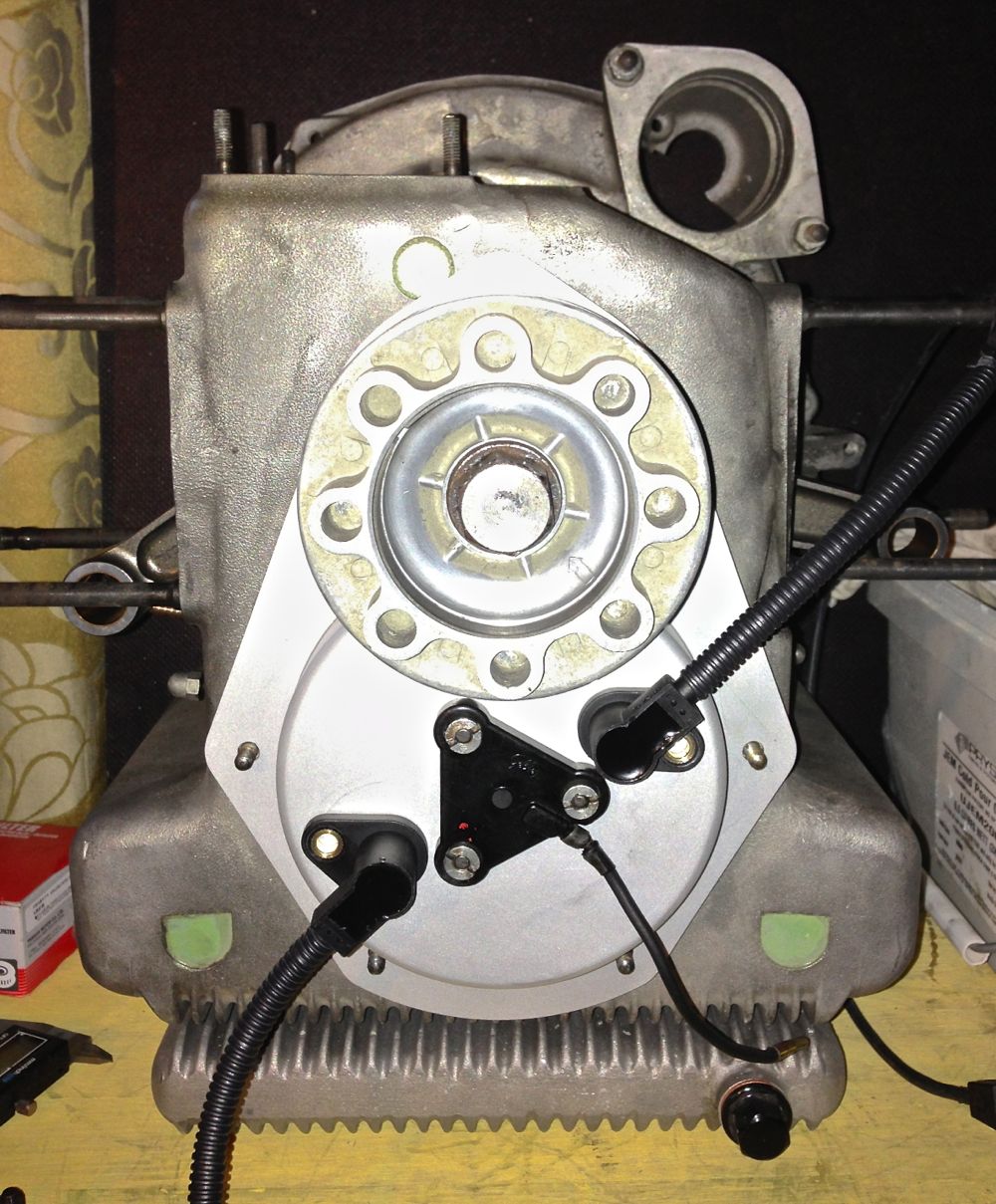
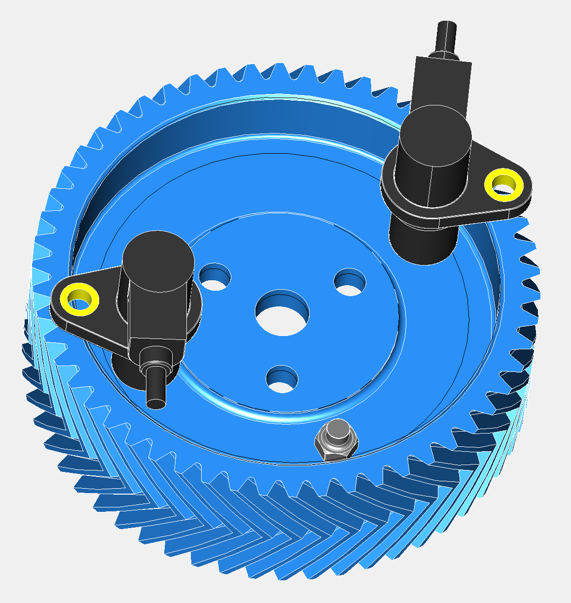
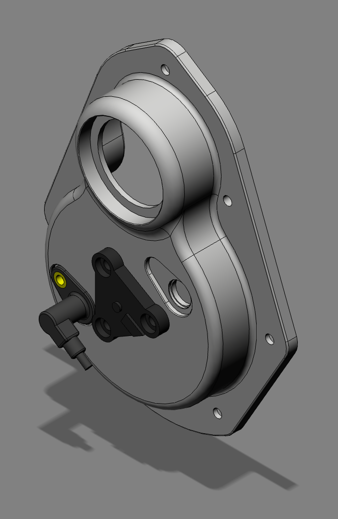
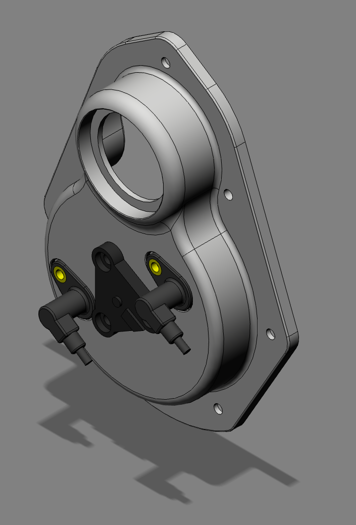
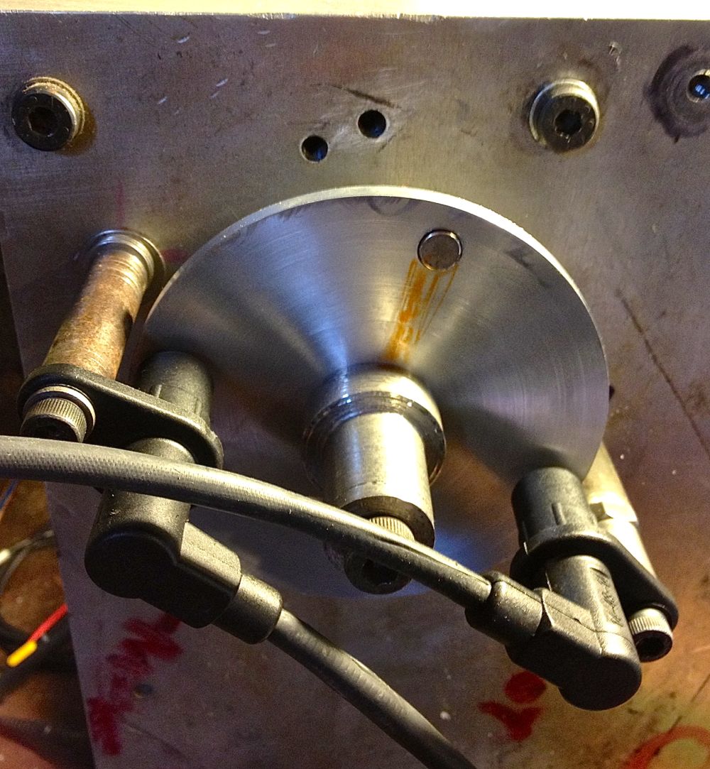
I noticed when I was testing the sensors that these parts are orientation sensitive, so I created an orientation map to help me when it came to fitting the sensors.
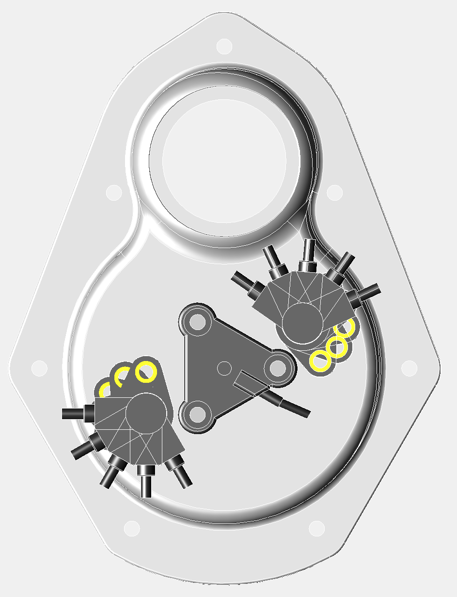
It was just a s well, because when I fitted the crankshaft pulley, I noticed the right hand sensor had very few options. The cable will foul the pulley, unless it is in the 1 or 2 o’clock positions, and it is best if it is tangental to the pulley, as this gives more room for dynamo V belt replacement. This is only really a consideration, as I am using sequential twin spark with the Imfsoft Ignition TCI module, and if I used a MicroSquirt, I could just use a single sensor and a toothed wheel. This will also be the case with electronic fuel injection too.
Notice how the Gelbey oil light sensor is rotated, which gives more clearance for sensor rotation.
Tangental orientation below.
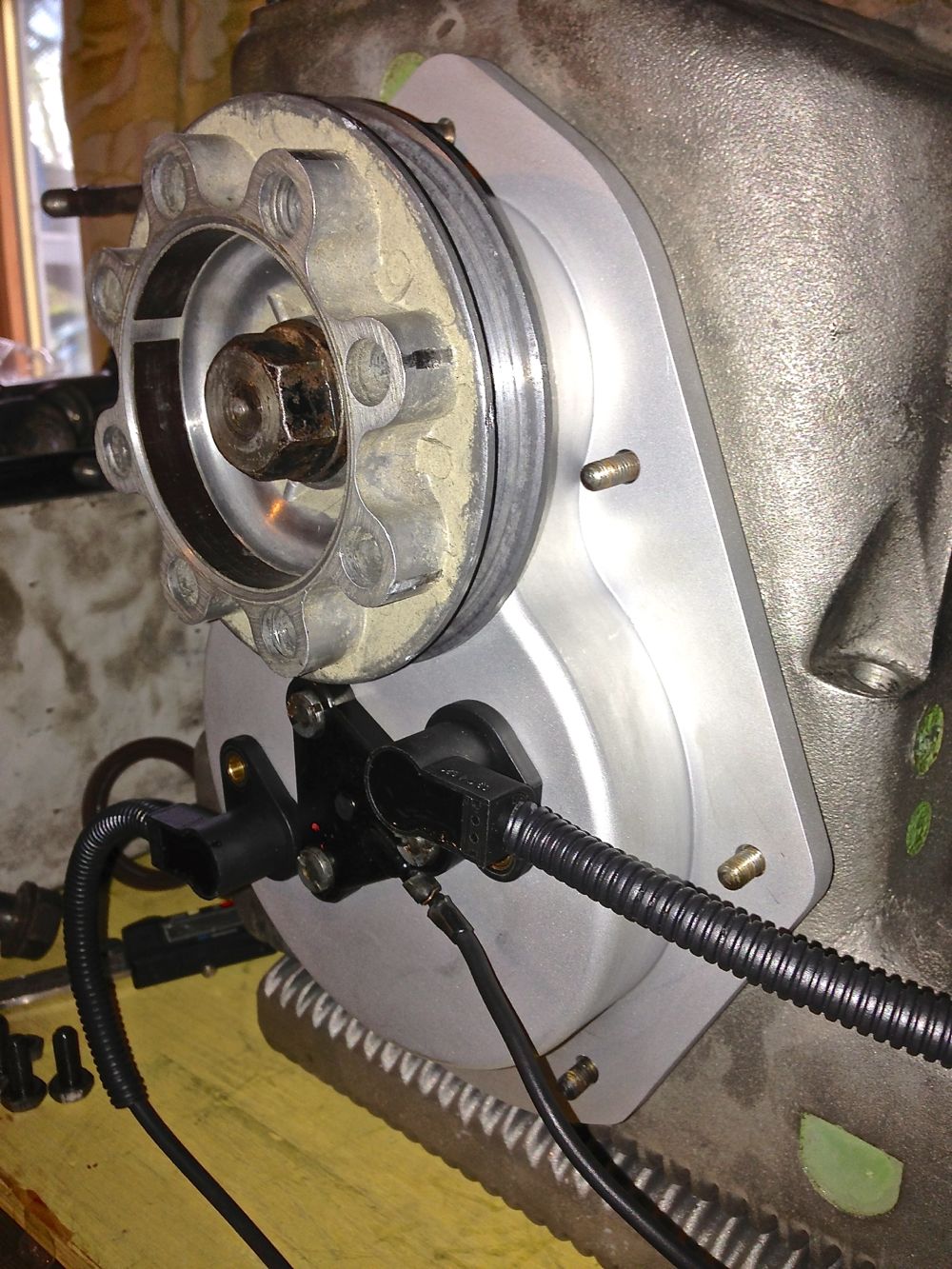
Next up was to check the cowling & fan fit
.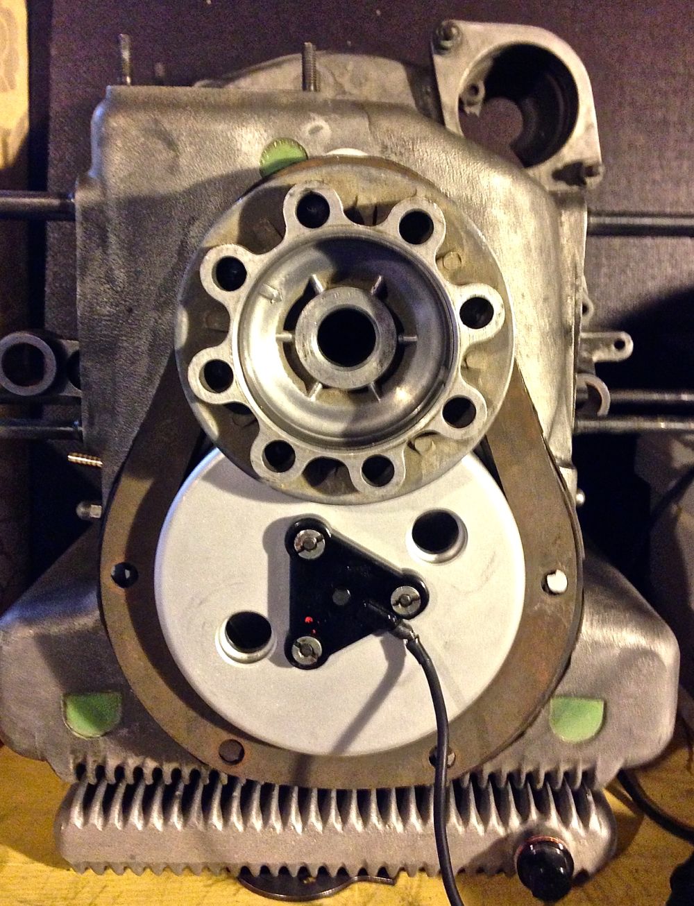
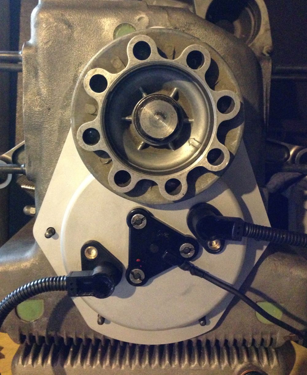
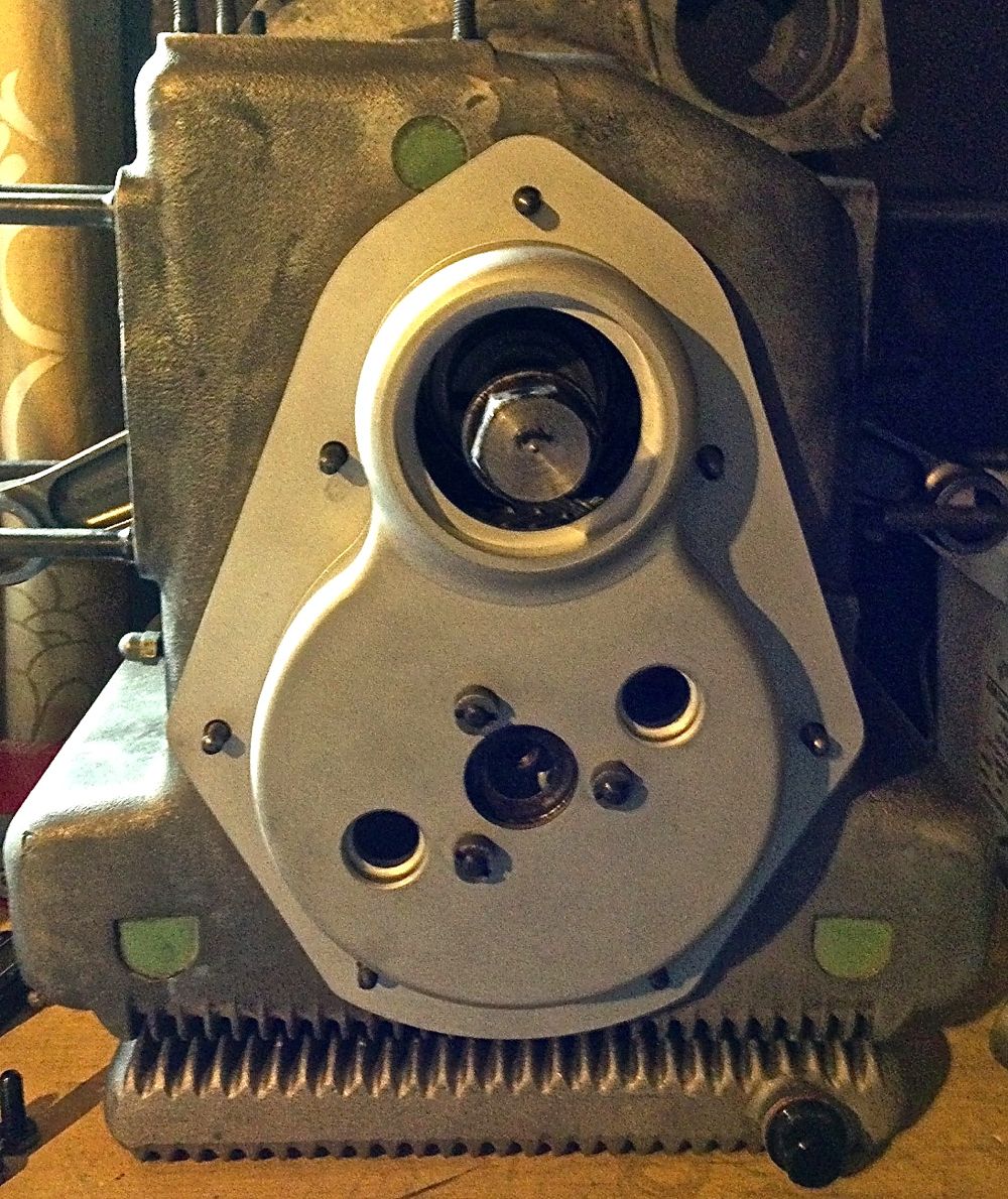
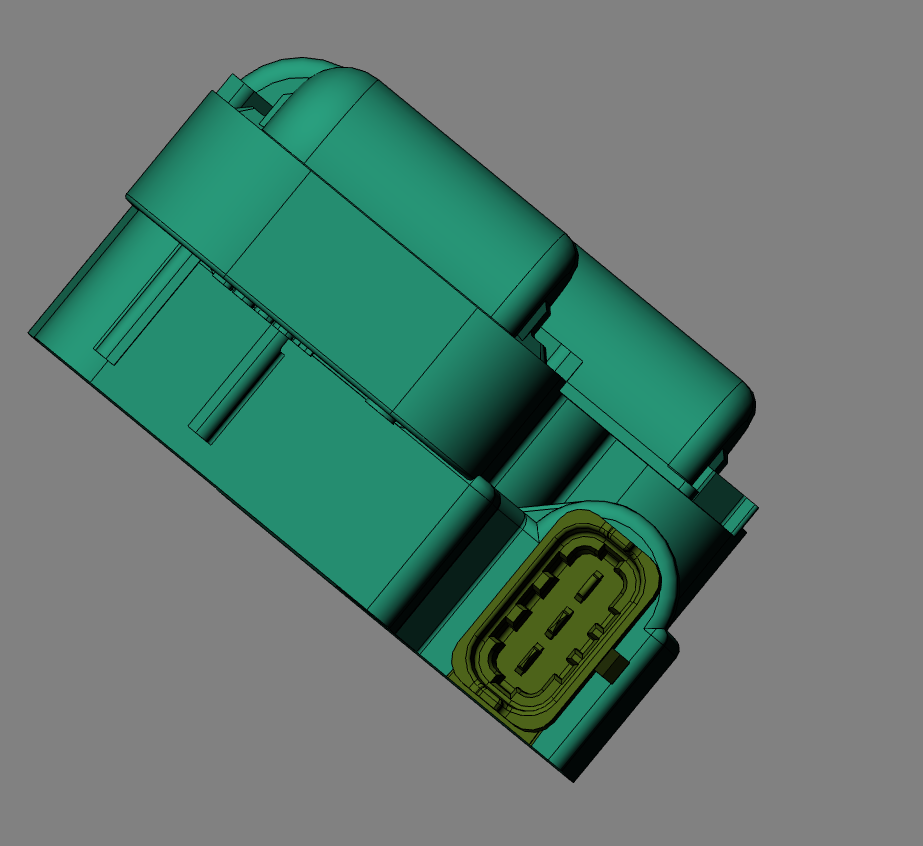
After this check the fan clearance, this is the front view, and how discreet is this cover. You wouldn’t realise it was there
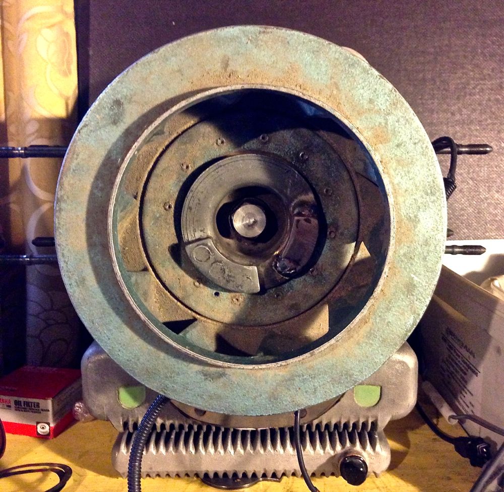
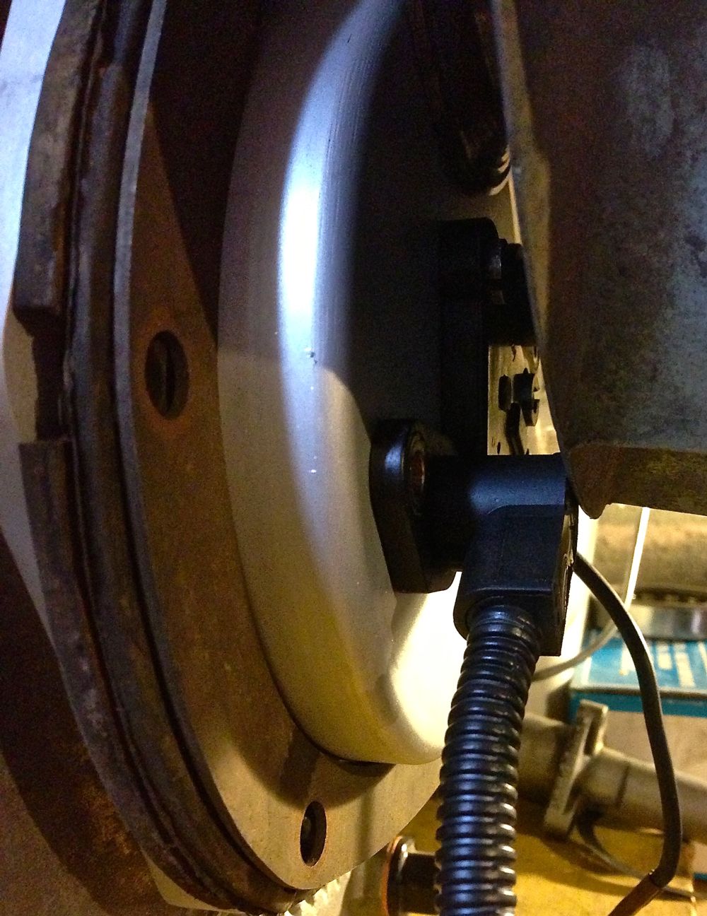
More importantly the clearance for the lower left hand sensor! Pretty tight, except the fan is pushed 5mm further forward if my measurements are right (phew)!
All in all, not a bad first stab, even if I do say so myself!
It was just a s well, because when I fitted the crankshaft pulley, I noticed the right hand sensor had very few options. The cable will foul the pulley, unless it is in the 1 or 2 o’clock positions, and it is best if it is tangental to the pulley, as this gives more room for dynamo V belt replacement. This is only really a consideration, as I am using sequential twin spark with the Imfsoft Ignition TCI module, and if I used a MicroSquirt, I could just use a single sensor and a toothed wheel. This will also be the case with electronic fuel injection too.
Notice how the Gelbey oil light sensor is rotated, which gives more clearance for sensor rotation.
Tangental orientation below.
Next up was to check the cowling & fan fit
.
After this check the fan clearance, this is the front view, and how discreet is this cover. You wouldn’t realise it was there
More importantly the clearance for the lower left hand sensor! Pretty tight, except the fan is pushed 5mm further forward if my measurements are right (phew)!
All in all, not a bad first stab, even if I do say so myself!
Panhard Front Timing Cover First Fit
04/05/13 12:43
Just a quick update again, as I have to jump on the lathe in a moment, more of a quick snap for Brian, as he’s got broadband now!
The first trial fit on a crankcase went exceptionally well, as the cover fits snuggly with no discernible play on the locating dowels.
There were two minor issues, one the oil light piston tab washer detail was slightly too small, and two, the O ring seal could be marginally tighter on the sensor holes, but all these have details have been corrected in the 3D model now, so the rest of this batch will be spot on.
I am extremely pleased with the results so far, and even better, there is sufficient room for the various trigger wheel configurations I have planned.
I will update the pictures again later.
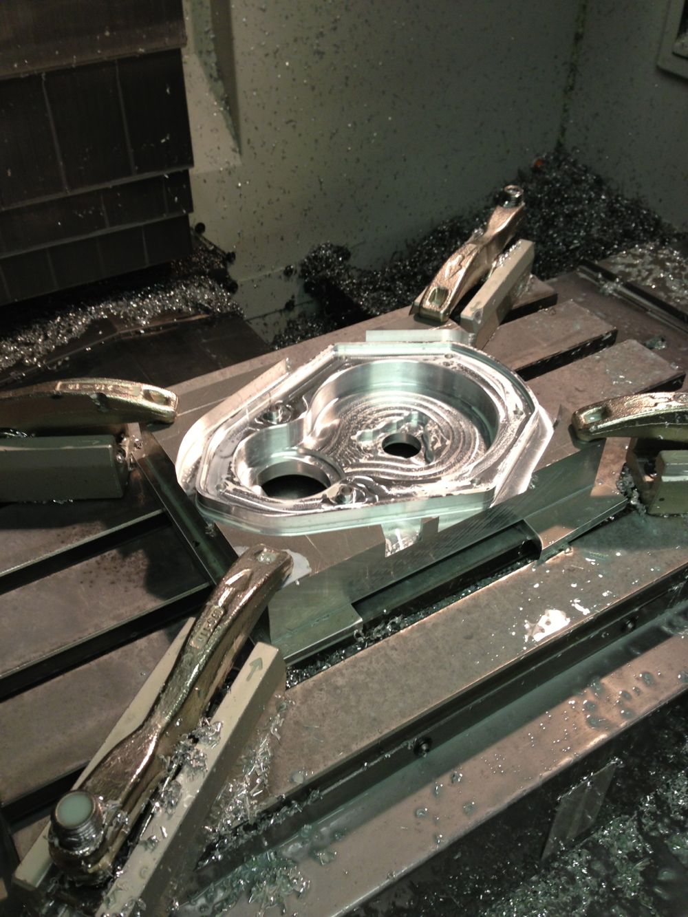
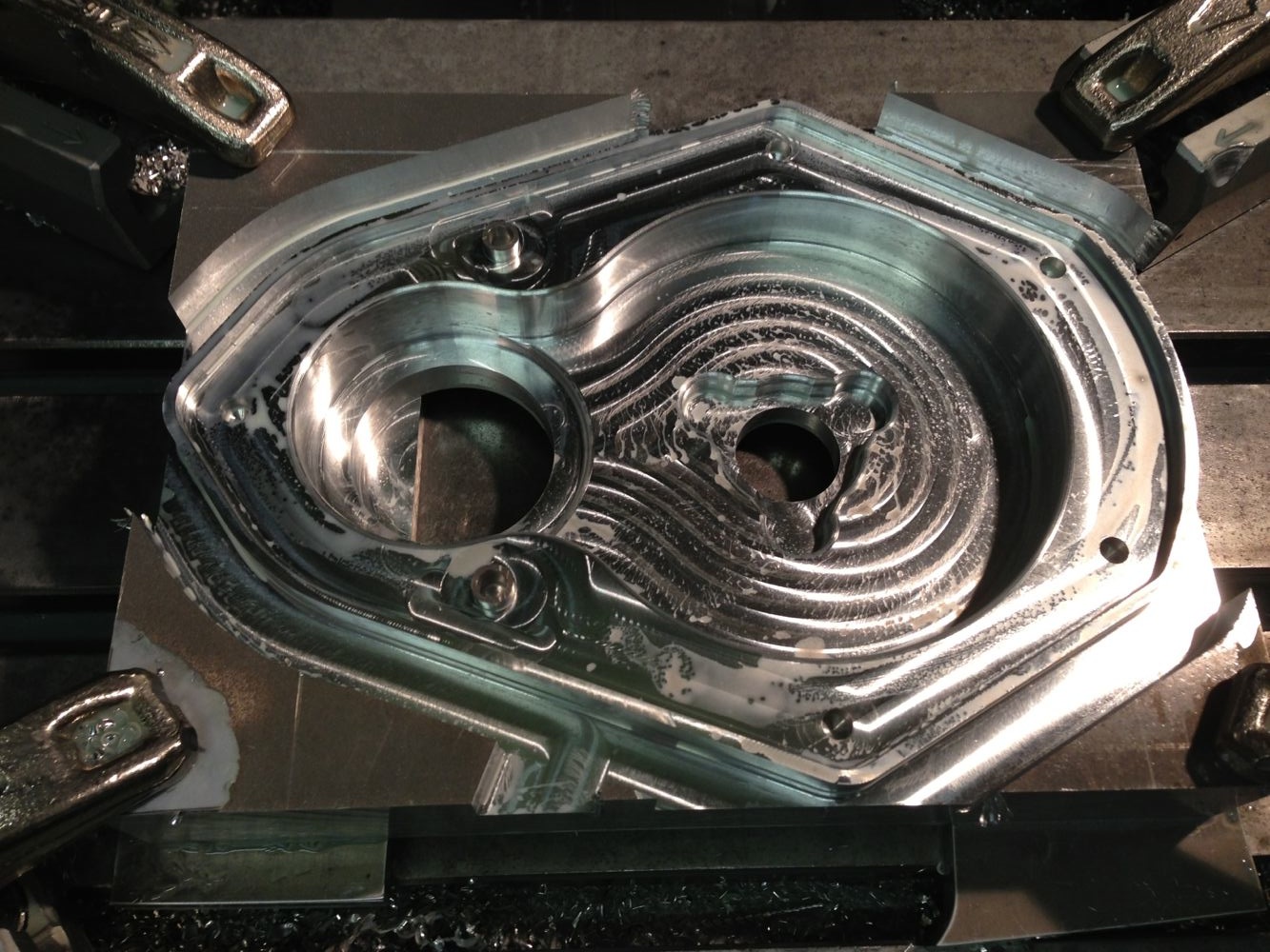
Panhard Front Timing Cover CNC Started
03/05/13 17:40
Panhard Front Timing Cover Modifications 5
14/04/13 10:13
I was burning the midnight oil last night, and I realised I made a mistake in drawing the crankshaft sensor, because it wasn’t the right shape. Ordinarily this wouldn’t have mattered, but the crankshaft sensor is rotation sensitive, and after double checking my bench rig, and mimicking the 3D CAD model positions on this, I found the error with the cable output.
The sensors can be deliberately rotated on the first batch of covers, as I will be drilling and tapping the M6 fixing screws to maximise trigger detection, but for the next generation of covers they will all be fully finished. I have tried to make the measurements as accurate as possible, but I expect this prototype cover might need a slight dimensional tweak for the second batch.
I have also made a decision to make the first batch twin sensor versions by drilling out both the sensor holes, and depending on demand, there might be a blanking plug fitted to convert to single sensor operation. It is pretty trivial to make one.
Correct sensor alignment & shape, suitable for Panhard camshaft rotation.
There was a slight mod to the cover internally, as there was an interference issue with the Gelbey oil light switch internal assembly, so the drawing has been modified again!
Here is the simple ferrous trigger fitted to an aluminium camshaft gear, which is just a turned down hex headed screw.
I am very confident that the system will work now as drawn, especially as chasing down the issue of twin trigger events with square cut ferrous edges, I also discovered these particular sensors run in oily environments, which was one of the criticisms I had got from a few Panhardistes about the timing cover that was still outstanding, even though it was a non issue for me, as motorcycle camshaft sensors do this already.
Panhard Front Timing Cover Modifications 4
12/04/13 22:42
Over the last few days I have been testing sensors with the Imfsoft ignition module, and it’s no surprise the Hall effect sensors are out performing the inductive ones. The results of my latest tests are a no brainer, and I have settled on a new Hall effect sensor, which is cheaper, has a longer supplied cable, and terrific performance.
If I used a strong magnet the inductive sensor had great performance at low cranking speeds, such that it would “start” with cranking handle, but when I changed the trigger to a plain ferrous material, the performance of the inductive sensor was obliterated by the Hall effect. It took 165 rpms before the inductive sensor would work, the Hall effect at less than 7 rpm. It was so good, the Hall effect would be triggered by the ferrous material, switch on the ignition module, and make a spark in a seemingly instantaneous action. I initially tried it with an 8mm diameter object, but when it was reduced to less than 5mm, it took nearer 400 rpms to trigger the inductive sensor, yet the Hall effect lost no slow speed performance, so that’s case closed on the sensor.
There was an observation that the square edged on sudden transitional tooth is a problem for the sensor at low speed, it must be a sawtooth or sinusoidal tooth profile to work well.
The only problem was it is now a different size, and so the fit is different in the timing cover, and this had to be modified yet again. Fortunately, the 3D modeller hadn’t started on my covers, so I have revised the drawing definitely for the last time.
This means, the timing cover will be suitable for a toothed wheel approach like before, or a single tooth set up with the Imfsoft unit, and depending on the number of sensors, whether you get wasted or sequential spark.
This is the final version!
Panhard Ignition Trigger Testing (video) 3
07/04/13 10:13
Just quick update, some video 480p clips, showing the crank speed sequential spark tests with an oversized air gap, and a quick snippet of sequential sparking at fast idle speed. The Top & bottom plugs are cylinder 1, and the middle two are cylinder 2, just in case you are wondering which is which., easy if you look at the first video really.
Panhard Twin Plugging & Ignition Options 2
07/04/13 02:26
So now I have sequential ignition, using the Imfsoft IgnitionTCI 6.1, an Audi ignition module, and single fire coils for a twin spark set up on the Panhard, but it is all moving upwards in price. The Imfsoft ignition is reasonably cost effective for its capabilities, switchable dual advance curves, two crank or camshaft sensor inputs, and two additional (analogue or digital) inputs that can modify the running advance curve. The Audi 4 x Inputs, 4 x outputs is needed to increase the outputs of the IgnitionTCI 6.1 without overloading the 15A limit for each output.
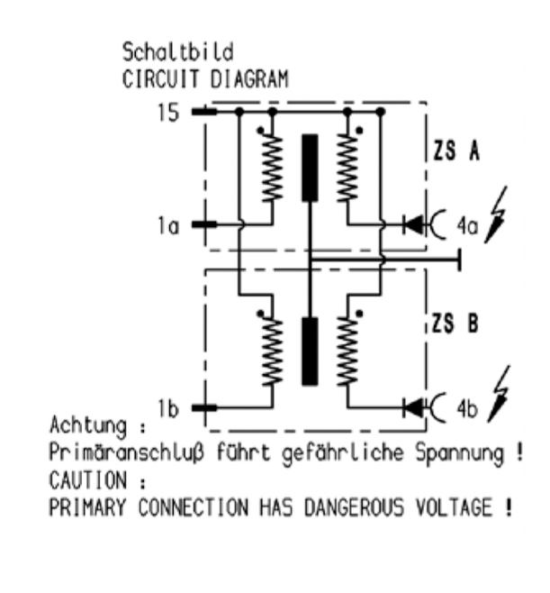
In an ideal world, it would be nice to use modern stick coils or pencil coils, but that’ll be for another day, because after trolling through the Bosch ignition catalogues, there is it seems a specially developed coil for twin spark engines.

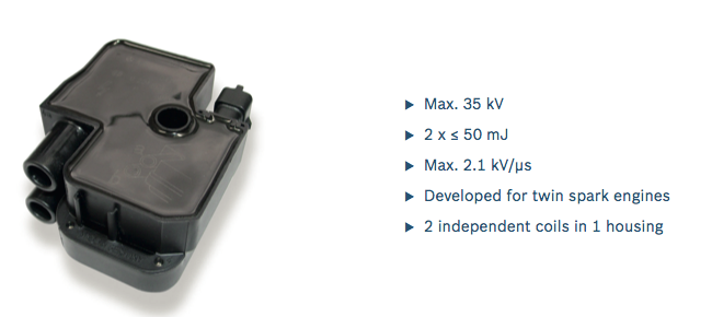
All I needed was a price and here is the Bosch info.
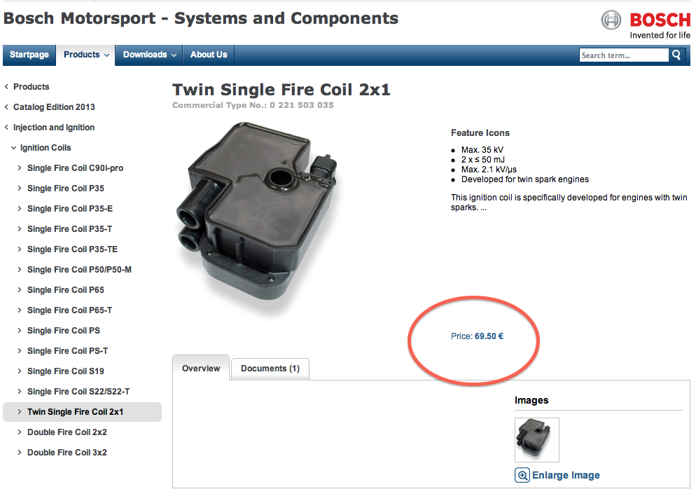
A quick phone call to a local motor factors and it ends up being £93 each!
I don’t come from a garage or vehicle maintenance background, so I didn’t recognise this coil type at first, and I was trying to work out whose engine it was used in. Alfa Romeo do a twin spark, but it has a top hat coil and a pigtail HT lead for the second plug. Honda do a twin plug engine, which uses a SAAB like strip of interconnected stick coils, but then its probably a Denso component. A further search on the internet, soon told me it was a Mercedes Benz application, so now there was more leads.
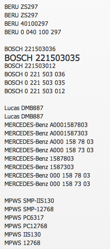
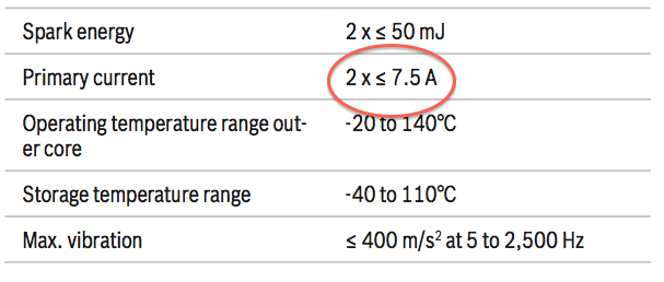
More searching on the internet and these cross references come up, so by trolling some more I can reduce it down to £50 each for a new Mapco version, so the cost is coming down. I already have the Audi ignition module from my motorcycle ignition work, plus some other four channel ignition drivers, but maybe this coils inputs could be paired (combining 1a & 1b), and possibly need an additional ignition control module?
Further digging revealed it could, remember the limit is 15A, so another good result.
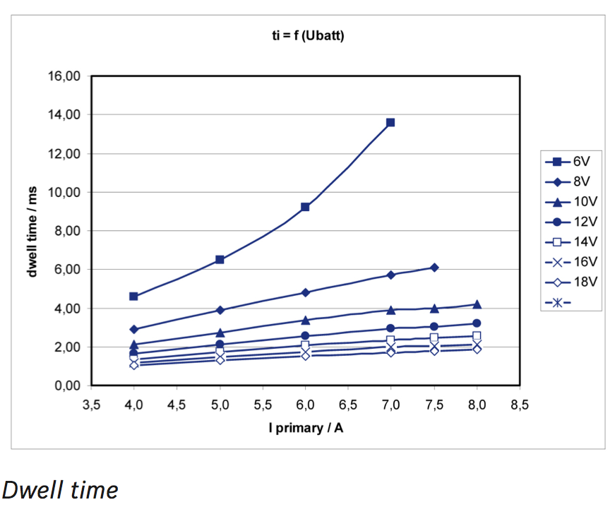
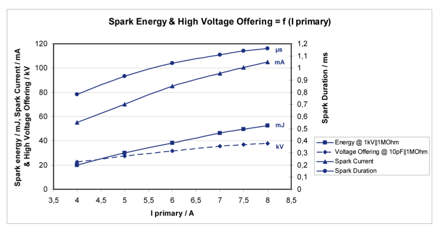
A further look at the dwell chart shows that it is possible to use the 15A limit of the 1A & 1B outputs of the Ignition TCI 6.1, as long as you limit the dwell time, and here’s the confirmation. Dwell and spark energy graphs below.
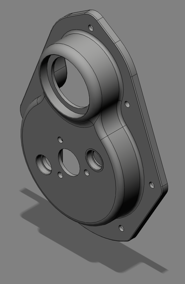
If you want a picture of the unit, here it is in CAD. The connector is a 3 way Bosch Kompakt or Compact type, and it uses Junior Timer or FASTON internals.
Hopefully the parcel in the post will drop in the door and I can test these units, and double check the current draw and spark quality. Thanks to Jean Paul Cesar for his collaboration on this project, because without it, I would have taken a wrong turn, especially trying to use the 2x2 coil pack, and taken longer to complete, when time is getting short to finish the engine for the 2013 International.
In an ideal world, it would be nice to use modern stick coils or pencil coils, but that’ll be for another day, because after trolling through the Bosch ignition catalogues, there is it seems a specially developed coil for twin spark engines.
All I needed was a price and here is the Bosch info.
A quick phone call to a local motor factors and it ends up being £93 each!
I don’t come from a garage or vehicle maintenance background, so I didn’t recognise this coil type at first, and I was trying to work out whose engine it was used in. Alfa Romeo do a twin spark, but it has a top hat coil and a pigtail HT lead for the second plug. Honda do a twin plug engine, which uses a SAAB like strip of interconnected stick coils, but then its probably a Denso component. A further search on the internet, soon told me it was a Mercedes Benz application, so now there was more leads.
More searching on the internet and these cross references come up, so by trolling some more I can reduce it down to £50 each for a new Mapco version, so the cost is coming down. I already have the Audi ignition module from my motorcycle ignition work, plus some other four channel ignition drivers, but maybe this coils inputs could be paired (combining 1a & 1b), and possibly need an additional ignition control module?
Further digging revealed it could, remember the limit is 15A, so another good result.
A further look at the dwell chart shows that it is possible to use the 15A limit of the 1A & 1B outputs of the Ignition TCI 6.1, as long as you limit the dwell time, and here’s the confirmation. Dwell and spark energy graphs below.
If you want a picture of the unit, here it is in CAD. The connector is a 3 way Bosch Kompakt or Compact type, and it uses Junior Timer or FASTON internals.
Hopefully the parcel in the post will drop in the door and I can test these units, and double check the current draw and spark quality. Thanks to Jean Paul Cesar for his collaboration on this project, because without it, I would have taken a wrong turn, especially trying to use the 2x2 coil pack, and taken longer to complete, when time is getting short to finish the engine for the 2013 International.
Panhard Twin Plugging & Ignition Options 1
06/04/13 11:35
It is one thing to twin plug a cylinder, it is a totally different thing to get the right quality sparks. There are two options, wasted or sequential twin plugging. I mistakenly thought I could achieve sequential twin plug sparking with double ended coils, when really it would have only been wasted, but it took a French friend to put me straight, thank you Jean Paul.
Originally, I was going to use stick coils, or pencil coils, but the Panhard heads and torsion bar castings do not lend themselves to a satisfactory fixing solution, plus time is running out, and the added complication of angling the spark plugs, using 10mm plugs and a bespoke adaptor seems like a lot of trouble for little gain.
Historically, Hampe did a wasted system over fifty years ago, using four standard coils, two times two wired in parallel, with an additional contact breaker placed inside the distributor, and an added cam to trigger this second set of points. Nowadays this wouldn’t be required, as you could use the OEM sequential points trigger and a modern ignition control module to switch on the additional coils, but this is digressing slightly.
What are the issues with twin plugging? Well it is nicely summed up here, in this article taken from the Vincent Owners Club if I remember correctly.
Now to sparks. Both Roger Haylett and Gordon Colquhoun want to know about double-ended coils and twin sparks - both having had problems. When fitting twin plugs into a head the concept of using a double-ended coil, fitted into the standard ignition system, may seem ideal, but it doesn't work out. Why? Well, examine where the double-ended coils come from. They are invariably from so-called idle-spark systems, where one cylinder is fired on its compression stroke, and the other end is feeding another cylinder, which will be on its induction stroke (though exactly where depends on whether it is a parallel twin, four, or vee-twin). What you need to know is that the voltage required to make a spark depends on the pressure of the gas it is trying to spark through. So, in an idle spark system, the voltage required is only slightly more than in a single-ended one, because one cylinder is under compression (say 150 psi), but the other isn't (ie, less than 15 psi). So almost all of the voltage appears on the firing cylinder, and a very weak, low voltage spark, occurs in the other one (usually not enough energy even to fire a mixture, which is why it works on vee-twins, which can be well on to the induction stroke, and filling with mixture). Try the same coil on a twin plug head and you need twice the voltage, which is way above the design criteria. So it may not fire reliably.
There are a variety of fixes. Best of the lot is to use a pair of coils in series, to drive the two plugs - preferably a pair of identical-type coils, but they don't need to be better matched than that. Of course, this requires half voltage coils- ok if you can find a pair of six volt ones to run on 12 volt (you might look at 12 volt ones with ballast resistors, and bypass the resistors which makes them six-eight volt types). A number of people have told me that, like Gordon, they have run coils in parallel, but theoretically, it isn't a good idea. Coils in parallel need to balance and so too does the sparking voltage of the plugs. If they don't go off together, then the single spark immediately loads one coil, which may suck power from the primary of the other, and the second spark may not occur. So it probably works better than the original double-ended coil, which misfires completely, but you may actually be running single spark some, or all, of the time, and not, necessarily, firing the same plug every time. Optimising the timing may be impossible, if single and twin optima are different, although the engine will not, necessarily, show ignition problems. However, if it works for you, I'm not going to say it doesn't - but I recommend the series arrangement.
If you are trying to do a Twin, then series or parallel, it makes for a lot of coils. Here, though, there is a further, attractive and sound, alternative, although it may mean altering your 'distributor', be it single-bump cam and one pair of points, or twin-bump cam and a single set of points. Instead, what you need is both the twin-bump cam and the twin points. Now fit a double-ended coil to each set of points, and wire each in conventional double-ended fashion, ie, one end to a plug on one cylinder and the other end to a plug on the other cylinder. Now you are not asking too much of either coil, but you will get twin sparks on each cylinder reliably. The idea extends to fours and sixes too, if you can find the appropriate multi-lobe cam and multi-points assembly - and work out exactly the right places to send the extra leads.
How am I going to do Brian’s engine?,
Well it looks like this
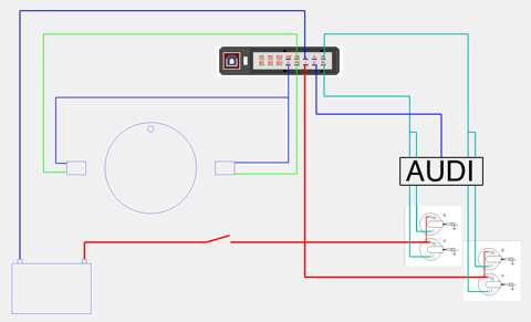
I n the above, I am using an Audi ignition control module, which has four inputs & outputs to trigger the GND signals from the programmable ignition module, which in turn feed two single fire coils per cylinder. This now gives a sequential ignition sequence to the firing order, and it should mean there is a good quality spark at all times. The last thing is I cannot use the standard coils I show in the schematic, as the Imfsoft ignition says “standard coils are not supported”, so I have to use modern single fire coils instead.
Incidentally you could do a wasted spark version, using two magnets, one sensor, and using a pair of say double fire coils (2CV, double ended motorcycle types) with one coil feeding the top plugs & the other the bottom plugs. This is essentially what Hampe did, but they were limited by using standard coils & a need to make a failsafe system, that could run of one set of points.
I have managed to get sequential twin spark working in theory using double fire motorcycle coils, but these won’t work because the coil voltage for the spark will be biased towards the cylinder under compression, but hopefully in the next few days a new set of compact twin single fire coils will arrive in the post, so I will find out whether the current draw is too much for the Imfsoft IgnitionTCI 6.1.
To be updated...
Originally, I was going to use stick coils, or pencil coils, but the Panhard heads and torsion bar castings do not lend themselves to a satisfactory fixing solution, plus time is running out, and the added complication of angling the spark plugs, using 10mm plugs and a bespoke adaptor seems like a lot of trouble for little gain.
Historically, Hampe did a wasted system over fifty years ago, using four standard coils, two times two wired in parallel, with an additional contact breaker placed inside the distributor, and an added cam to trigger this second set of points. Nowadays this wouldn’t be required, as you could use the OEM sequential points trigger and a modern ignition control module to switch on the additional coils, but this is digressing slightly.
What are the issues with twin plugging? Well it is nicely summed up here, in this article taken from the Vincent Owners Club if I remember correctly.
Now to sparks. Both Roger Haylett and Gordon Colquhoun want to know about double-ended coils and twin sparks - both having had problems. When fitting twin plugs into a head the concept of using a double-ended coil, fitted into the standard ignition system, may seem ideal, but it doesn't work out. Why? Well, examine where the double-ended coils come from. They are invariably from so-called idle-spark systems, where one cylinder is fired on its compression stroke, and the other end is feeding another cylinder, which will be on its induction stroke (though exactly where depends on whether it is a parallel twin, four, or vee-twin). What you need to know is that the voltage required to make a spark depends on the pressure of the gas it is trying to spark through. So, in an idle spark system, the voltage required is only slightly more than in a single-ended one, because one cylinder is under compression (say 150 psi), but the other isn't (ie, less than 15 psi). So almost all of the voltage appears on the firing cylinder, and a very weak, low voltage spark, occurs in the other one (usually not enough energy even to fire a mixture, which is why it works on vee-twins, which can be well on to the induction stroke, and filling with mixture). Try the same coil on a twin plug head and you need twice the voltage, which is way above the design criteria. So it may not fire reliably.
There are a variety of fixes. Best of the lot is to use a pair of coils in series, to drive the two plugs - preferably a pair of identical-type coils, but they don't need to be better matched than that. Of course, this requires half voltage coils- ok if you can find a pair of six volt ones to run on 12 volt (you might look at 12 volt ones with ballast resistors, and bypass the resistors which makes them six-eight volt types). A number of people have told me that, like Gordon, they have run coils in parallel, but theoretically, it isn't a good idea. Coils in parallel need to balance and so too does the sparking voltage of the plugs. If they don't go off together, then the single spark immediately loads one coil, which may suck power from the primary of the other, and the second spark may not occur. So it probably works better than the original double-ended coil, which misfires completely, but you may actually be running single spark some, or all, of the time, and not, necessarily, firing the same plug every time. Optimising the timing may be impossible, if single and twin optima are different, although the engine will not, necessarily, show ignition problems. However, if it works for you, I'm not going to say it doesn't - but I recommend the series arrangement.
If you are trying to do a Twin, then series or parallel, it makes for a lot of coils. Here, though, there is a further, attractive and sound, alternative, although it may mean altering your 'distributor', be it single-bump cam and one pair of points, or twin-bump cam and a single set of points. Instead, what you need is both the twin-bump cam and the twin points. Now fit a double-ended coil to each set of points, and wire each in conventional double-ended fashion, ie, one end to a plug on one cylinder and the other end to a plug on the other cylinder. Now you are not asking too much of either coil, but you will get twin sparks on each cylinder reliably. The idea extends to fours and sixes too, if you can find the appropriate multi-lobe cam and multi-points assembly - and work out exactly the right places to send the extra leads.
How am I going to do Brian’s engine?,
Well it looks like this
I n the above, I am using an Audi ignition control module, which has four inputs & outputs to trigger the GND signals from the programmable ignition module, which in turn feed two single fire coils per cylinder. This now gives a sequential ignition sequence to the firing order, and it should mean there is a good quality spark at all times. The last thing is I cannot use the standard coils I show in the schematic, as the Imfsoft ignition says “standard coils are not supported”, so I have to use modern single fire coils instead.
Incidentally you could do a wasted spark version, using two magnets, one sensor, and using a pair of say double fire coils (2CV, double ended motorcycle types) with one coil feeding the top plugs & the other the bottom plugs. This is essentially what Hampe did, but they were limited by using standard coils & a need to make a failsafe system, that could run of one set of points.
I have managed to get sequential twin spark working in theory using double fire motorcycle coils, but these won’t work because the coil voltage for the spark will be biased towards the cylinder under compression, but hopefully in the next few days a new set of compact twin single fire coils will arrive in the post, so I will find out whether the current draw is too much for the Imfsoft IgnitionTCI 6.1.
To be updated...
Panhard Front Timing Cover Modifications 3
03/04/13 22:27
I instructed the 3D modeller to go ahead and make four of these front covers, I have orders for two, and I have decided to make two to suit the Peugeot sensors and make two more plain variants, without sensor locations. I will rework these to suit later, as it gives me a platform to try other sensor options later.
The new covers will both have single sensor locations, with the ability to machine out the other location, which does not have a through hole, so it is essentially an integrated blanking plug. I need this other sensor location for twin plugging when using the Ignition TCI6.1 from Imfsoft, but if I revert to a toothed wheel configuration, the single sensor will be enough to satisfy the plentiful options that exist for standalone programmable engine management systems.
Single sensor version with Peugeot 405/406 crankshaft sensor, and below this, the twin sensor version.
I shall order a few 45x68x10 Viton R23 seals for the front pulley aperture in the next few days, and possibly book these in at the anodisers for a coating of OEM black, when they are completed.
Panhard Ignition Imfsoft Software 1
03/04/13 22:02
A little update on my observations so far on using the Imfsoft software that comes with the IgnitionTCI 6.1
I have noticed I can get a buffer error, and the program locks out, and as a result I have to close Windows XP and restart. I’ll get in touch with the folks at Imfsoft and see if it’s a MAc emulation thing or Windows related.
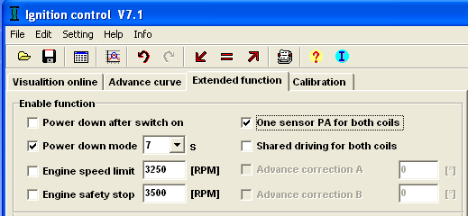
I have been reading and writing files to the unit, and I noticed that I managed to alter the ignition settings by checking the these boxes. It’s covered in the manual what they mean, but in my case they were unchecked and I stumbled upon the right behaviour.
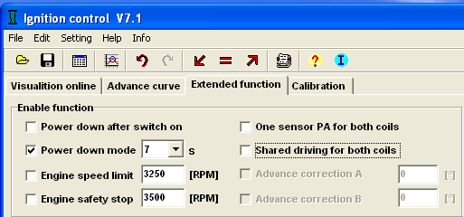
This gives sequential spark from two sensors, and two coils. This is what is required for sequential twin plugging on a Panhard twin.
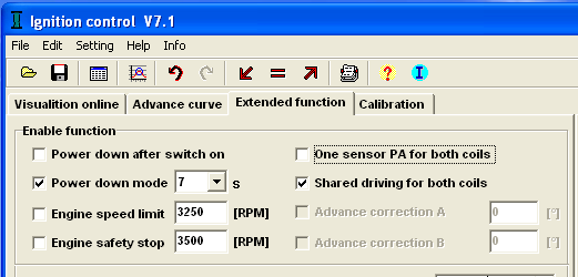
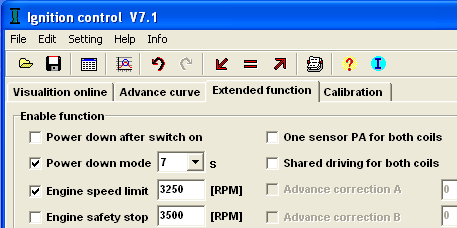
This gives shared sparks on both coil outputs, and a spark every time it passes a sensor, so in a sense it’s converts the above sequential into wasted spark for twin plugged heads, or wasted spark from two sensors.
This is the typical wasted spark set up for a twin, if you are using a twin ended coil, but the coil and sensor have to be in the PA inputs and outputs. You would use this setting for a standard single plug cylinders on a Panhard with a twin ended coil.
Another thing, if you check the Engine safety stop box, the sparks stop at this threshold and if you slow down, they DO NOT restart, so this is a KILL switch upper limit. I assume that when the engine stops, you can restart as per normal. The Engine speed limit IS the rev limiter, and it does work OK, when you slow the rig down , the spark is restored.
I have noticed I can get a buffer error, and the program locks out, and as a result I have to close Windows XP and restart. I’ll get in touch with the folks at Imfsoft and see if it’s a MAc emulation thing or Windows related.
I have been reading and writing files to the unit, and I noticed that I managed to alter the ignition settings by checking the these boxes. It’s covered in the manual what they mean, but in my case they were unchecked and I stumbled upon the right behaviour.
This gives sequential spark from two sensors, and two coils. This is what is required for sequential twin plugging on a Panhard twin.
This gives shared sparks on both coil outputs, and a spark every time it passes a sensor, so in a sense it’s converts the above sequential into wasted spark for twin plugged heads, or wasted spark from two sensors.
This is the typical wasted spark set up for a twin, if you are using a twin ended coil, but the coil and sensor have to be in the PA inputs and outputs. You would use this setting for a standard single plug cylinders on a Panhard with a twin ended coil.
Another thing, if you check the Engine safety stop box, the sparks stop at this threshold and if you slow down, they DO NOT restart, so this is a KILL switch upper limit. I assume that when the engine stops, you can restart as per normal. The Engine speed limit IS the rev limiter, and it does work OK, when you slow the rig down , the spark is restored.
Panhard Ignition Trigger Testing 2
03/04/13 18:17
I had a request from a fellow Panhardista to look at the ignition units performance at 8V dc, so after work today I started to have a play, and I hooked up a zener diode, and a resistor to pull the 12V battery down to 6V.
I connected up this 6V to the IgnitionTCI 6.1 and used a cordless drill to rotate the trigger wheel on the rig, and it performed exactly as yesterday!
This is too good, so I thought I’d drop the voltage some more, so I added a LED, and pulled it down to just over 4V, whilst the screen video was running (edited out), which to be fair is 1V over the rated minimum for the ignition, and yet again the programmable ignition performed admirably. Good result.
Here’s a video clip, a little bit too long, but you get some idea. I used the drill slowly at first, then held it steady (around 65 rpm), and then went a little faster. The smaller dial is the advance curve, and it is jumping up to reach it’s lowest value. The lowest speed it can calculate advance is 180 rpm, so most of time it is below this.
Afterwards, I added a second sensor, but used the first sensors wiring that fed the Imfsoft ignition unit, to check the sensor. i also increased the air gap to 4mm from 2.5mm, to see how this would affect slow speed cranking performance, and there was no change.
I then wired up the first sensor again, so I had two sensors 180º apart at the cam, therefore 360º apart at the crankshaft, and checked I was getting sequential ignition, AND I was.
Better still I was able to flick start a spark, by rotating the wheel magnet past the sensor. This is a bit like using a starting handle, which is even more impressive.
I am still using the inductive sensors from a Peugeot 405/406, and to be honest I am not thinking of changing this set up. I know a Hall effect sensor has greater tolerance to interference, but these sensors do have a separate ground pin, and they work well enough for me. Plus the air gap was at 4mm by the time I had finished testing, so that gives plenty of tolerance to concerns about the magnetic tips collecting ferrous particles.
The only thing I am likely to change is the size & quality of the magnet, because the new one will be a smaller diameter & made of SmCo26, a high temperature samarium cobalt variant.
Panhard Ignition Trigger Testing 1
01/04/13 11:03
Easter Monday Bank Holiday, and April 1st too, interesting mix, almost escaped the usual pranks, 55 minutes to go!
I thought I’d do something less taxing today, and tinker with the ignition and double check the Peugeot sensors work OK.
I have the Imfsoft ignition unit, and the software up and running on the desktop, so I just need to make a test loom, so I can try different ignition wheels. I also have a MicroSquirt v2 & v3, so over the next few weeks, when I am waiting for parts, I will play with these too.
Here’s the rig, the old trusty washing machine motor & variable speed drive, complete with Peugeot sensor and simple magnetic trigger. I’ll be using a smaller Samarium Cobalt magnet in Brian’s engine (SmCo26 to be precise) which is safe up to 250-300ºC, which is more than enough!
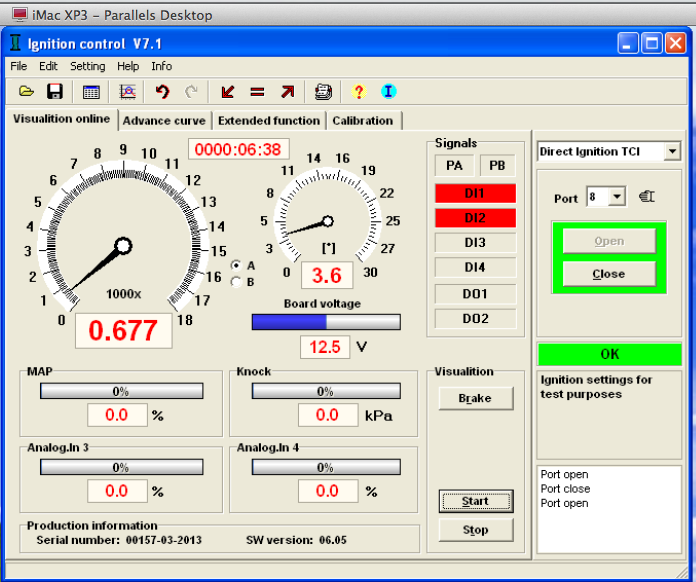
Here’s a typical low grade pocket oscilloscope trace, with the disc turning at around 600 rpm.
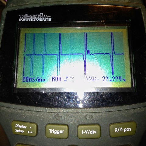
Very clean & strong spikes, which should mean good recognition at the ignition unit, and sure enough it does…with the wheel spinning at 677 t/min (the slowest my motor will go), the Imfsoft Ignition TCI glows green...
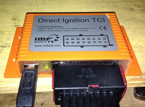
…and the display starts to register the RPMs.
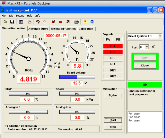
As the revs rise, obviously things get better. I went above my anticipated speeds, to check there was no over voltage faults, but the reading was steady in the software window.
This screen grab is actually displaying camshaft speed, which is half the actual engine revs of 9638 t/min.
The ultimate test is how slow can the engine turn and still be recognised by the ignition controller. I have had the MicroSquirt B&G code trigger at 50 rpm, and the MSExtra code trigger at 24 rpm, but I was surprised to see the Imfsoft unit go this low as well. Here’s a screen grab in a movie format, this time using a cordless drill to rotate the trigger wheel.
I thought I’d do something less taxing today, and tinker with the ignition and double check the Peugeot sensors work OK.
I have the Imfsoft ignition unit, and the software up and running on the desktop, so I just need to make a test loom, so I can try different ignition wheels. I also have a MicroSquirt v2 & v3, so over the next few weeks, when I am waiting for parts, I will play with these too.
Here’s the rig, the old trusty washing machine motor & variable speed drive, complete with Peugeot sensor and simple magnetic trigger. I’ll be using a smaller Samarium Cobalt magnet in Brian’s engine (SmCo26 to be precise) which is safe up to 250-300ºC, which is more than enough!
Here’s a typical low grade pocket oscilloscope trace, with the disc turning at around 600 rpm.
Very clean & strong spikes, which should mean good recognition at the ignition unit, and sure enough it does…with the wheel spinning at 677 t/min (the slowest my motor will go), the Imfsoft Ignition TCI glows green...
…and the display starts to register the RPMs.
As the revs rise, obviously things get better. I went above my anticipated speeds, to check there was no over voltage faults, but the reading was steady in the software window.
This screen grab is actually displaying camshaft speed, which is half the actual engine revs of 9638 t/min.
The ultimate test is how slow can the engine turn and still be recognised by the ignition controller. I have had the MicroSquirt B&G code trigger at 50 rpm, and the MSExtra code trigger at 24 rpm, but I was surprised to see the Imfsoft unit go this low as well. Here’s a screen grab in a movie format, this time using a cordless drill to rotate the trigger wheel.
