Nov 2012
Panhard Crankshaft Truing
04/11/12 17:30 Filed in: Panhard Engine
As I said in my blog, it was a little too cold to work in the attic today, so I spent a few hours at the workshop. I had some bespoke round bar stock lying around, that I was planning on making a crankshaft truing tool, but I wasn’t ready to mess with crankshafts whilst I was doing all the liner related work. Anyway that is virtually done now, bar a phone call to the piston company, so it was time to jump on the Elliot mill, and make a new tool.
This is what I had in mind, but I was limited by what bullnose endmills I had, so I used a smaller radius than I would have liked.
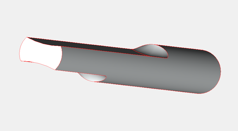
After a couple of hours, it was done. It took longer because I needed to keep checking by placing it in a crankshaft making sure I wasn’t taking too much metal away.
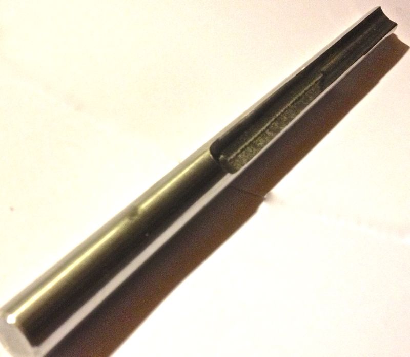
As I was making it I was testing it in Martin McClarence’s crankshaft that had turned. Fortunately it was the rear web that had moved, so I could refine the size of the tool to fit it.
Imagine my surprise when i got home and tested Brian’s crankshaft, and I discovered this had moved ever so slightly on the front web. I knew the rear web had moved, but interestingly it had been pulled outwards, because the crankshaft was too long between the main bearings. I can only put this down to rear bearing movement, due to a shimming error in the rear bearing backplate, but this was assisted by the oscillating crank due to the misalignment.
Anyway, the front web of the crankshaft is true now, after giving it a very hefty whack with the #4 Thor copper hammer, but the rear web is ever so slightly out. Next up on the crank is to press it together again, so the rear web has the correct connecting rod clearance, and then I’ll true the crankshaft up finally.
This is what I had in mind, but I was limited by what bullnose endmills I had, so I used a smaller radius than I would have liked.
After a couple of hours, it was done. It took longer because I needed to keep checking by placing it in a crankshaft making sure I wasn’t taking too much metal away.
As I was making it I was testing it in Martin McClarence’s crankshaft that had turned. Fortunately it was the rear web that had moved, so I could refine the size of the tool to fit it.
Imagine my surprise when i got home and tested Brian’s crankshaft, and I discovered this had moved ever so slightly on the front web. I knew the rear web had moved, but interestingly it had been pulled outwards, because the crankshaft was too long between the main bearings. I can only put this down to rear bearing movement, due to a shimming error in the rear bearing backplate, but this was assisted by the oscillating crank due to the misalignment.
Anyway, the front web of the crankshaft is true now, after giving it a very hefty whack with the #4 Thor copper hammer, but the rear web is ever so slightly out. Next up on the crank is to press it together again, so the rear web has the correct connecting rod clearance, and then I’ll true the crankshaft up finally.
Comments
Panhard Cylinder Liner Rebore Update 8
03/11/12 15:39 Filed in: Panhard Piston | Whatton
I was dropping something off at the workshop, and so I thought I’d look at the cylinder bore sizing with respect to temperature.
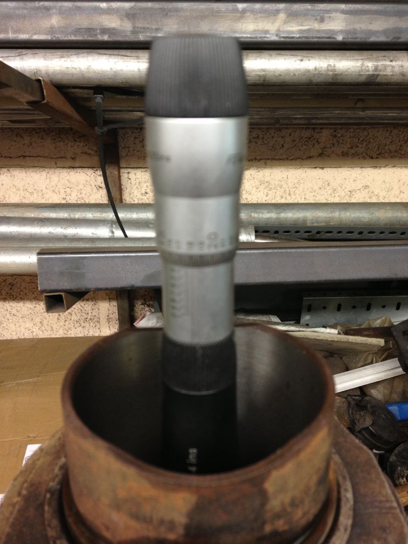
I wanted a rough idea, as too how much the cylinder would grow, and at what temperature could I expect the tapered bore to become parallel. I devised a really simple experiment, using a soft flame large propane torch ( no time for an oil bath etc), an infra red thermometer, and a three point micrometer, I quickly took snapshots of the sizes I was seeing on the micrometer, as I increased the temperature.
The idea was I’d measure the liner cold (today 5ºC), then about 50ºC, 100ºC and finally about 120ºC. These were just ball park figures, and the blow torch would be aimed around the cylinder finning roughly at the combustion chamber position. The temperatures were taken on the same spot, a nice black area, and the twin laser beams were focussed on this consistently. The cylinder was warmed past the temperature required and then allowed to drop to reach the desired test temperature. This way the heat would be soaking into the components more consistently.
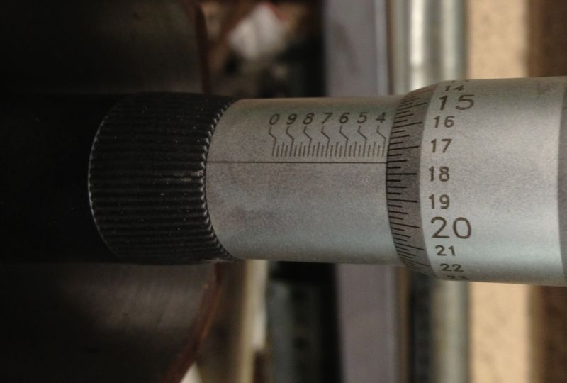
As it was a little warmer, than yesterday, the cold bore at the top of the liner measured
Next the cylinder was warmed up to just over 50ºC, and new readings taken, but each time I rested the micrometer in the setting ring to dissipate any heat build up caused by taking the reading. the reading shows the new top bore size, around 0.0025” larger on just 50ºC.
The bit just a bit further down was measured at about 0.0035” larger.
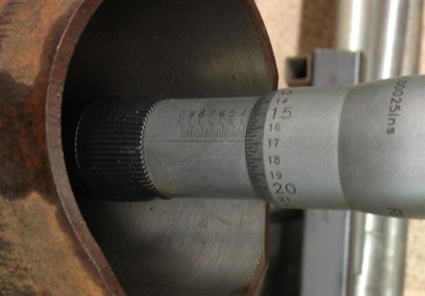
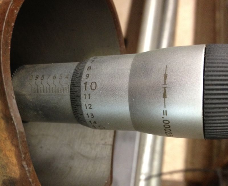
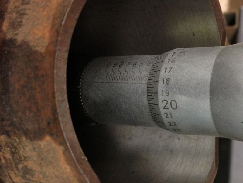
So then the cylinder was heated to just over 100ºC, and more measurements taken, and the top of the liner was reading about “16” now( another 2.5 thou larger). The middle of the liner had opened up further too, and even more lower down, as shown below
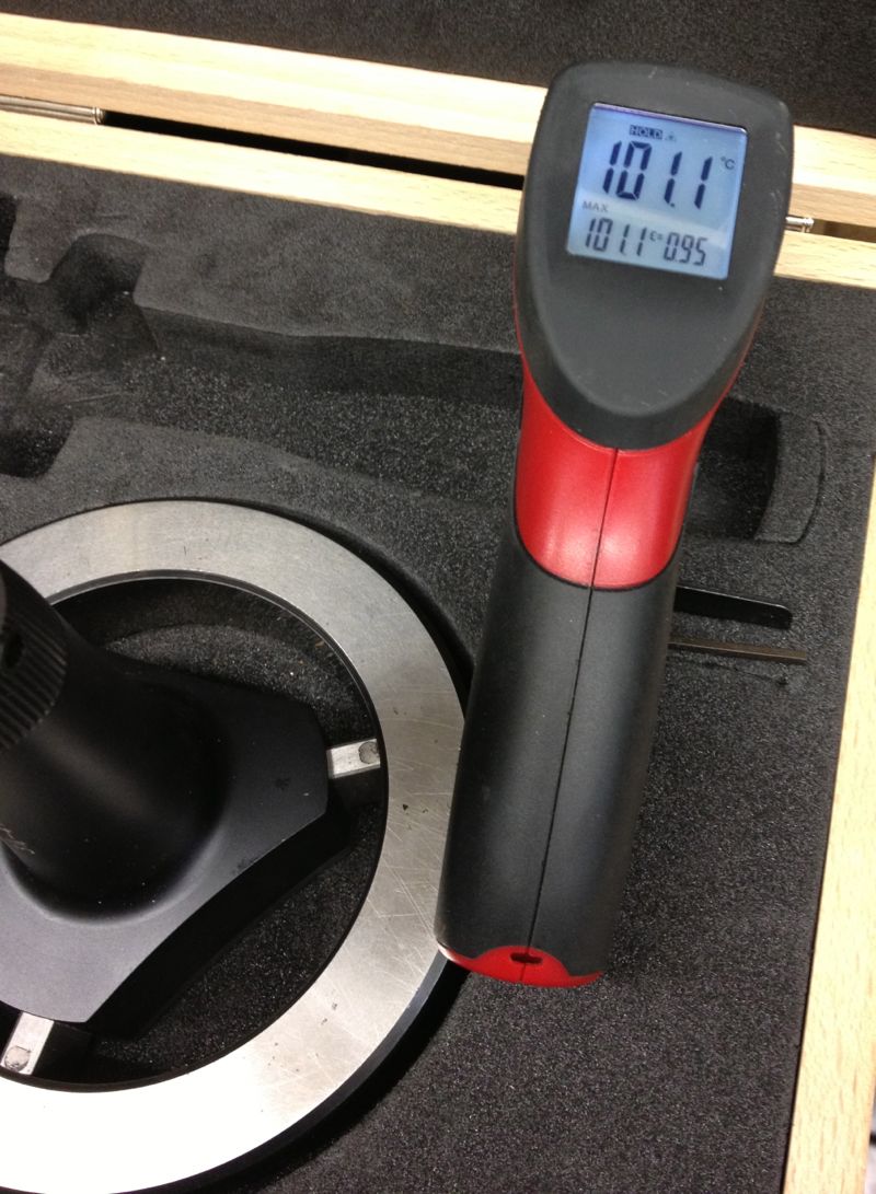
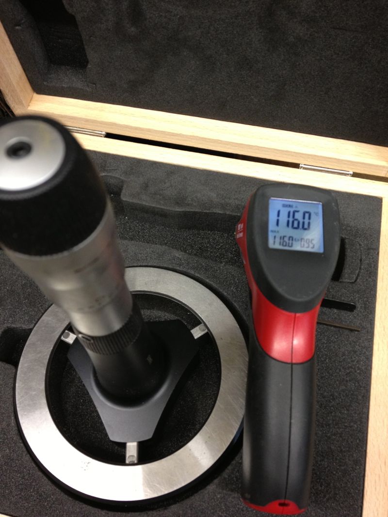
Picture below showing the setting ring and temperature at the moment of measuring.
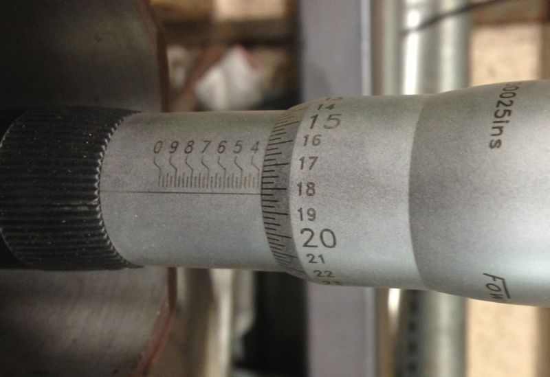
Then I heated the cylinder to about 130ºC, and let it cool slightly, and also took more measurements at the following temperature (116ºC) and then I noticed this!
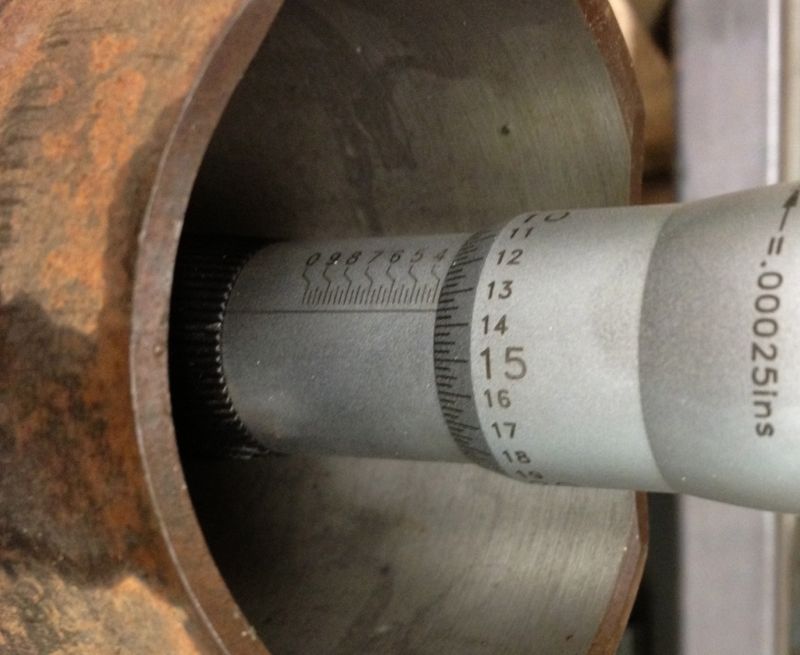
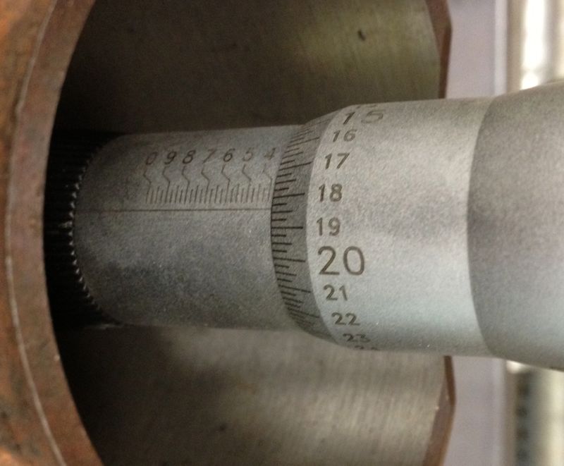
Top of liner closest to the combustion chamber measured “18” the same as the middle of the liner and the base of the liner was nearly the same, as the two images show.
Middle measurement was blurred, but you can see it is on the “18” mark
Conclusion, at around 120ºC the cylinder casting expands enough to become parallel, so now I have a figure I can work from to set my piston clearances too.
I wanted a rough idea, as too how much the cylinder would grow, and at what temperature could I expect the tapered bore to become parallel. I devised a really simple experiment, using a soft flame large propane torch ( no time for an oil bath etc), an infra red thermometer, and a three point micrometer, I quickly took snapshots of the sizes I was seeing on the micrometer, as I increased the temperature.
The idea was I’d measure the liner cold (today 5ºC), then about 50ºC, 100ºC and finally about 120ºC. These were just ball park figures, and the blow torch would be aimed around the cylinder finning roughly at the combustion chamber position. The temperatures were taken on the same spot, a nice black area, and the twin laser beams were focussed on this consistently. The cylinder was warmed past the temperature required and then allowed to drop to reach the desired test temperature. This way the heat would be soaking into the components more consistently.
As it was a little warmer, than yesterday, the cold bore at the top of the liner measured
Next the cylinder was warmed up to just over 50ºC, and new readings taken, but each time I rested the micrometer in the setting ring to dissipate any heat build up caused by taking the reading. the reading shows the new top bore size, around 0.0025” larger on just 50ºC.
The bit just a bit further down was measured at about 0.0035” larger.
So then the cylinder was heated to just over 100ºC, and more measurements taken, and the top of the liner was reading about “16” now( another 2.5 thou larger). The middle of the liner had opened up further too, and even more lower down, as shown below
Picture below showing the setting ring and temperature at the moment of measuring.
Then I heated the cylinder to about 130ºC, and let it cool slightly, and also took more measurements at the following temperature (116ºC) and then I noticed this!
Top of liner closest to the combustion chamber measured “18” the same as the middle of the liner and the base of the liner was nearly the same, as the two images show.
Middle measurement was blurred, but you can see it is on the “18” mark
Conclusion, at around 120ºC the cylinder casting expands enough to become parallel, so now I have a figure I can work from to set my piston clearances too.
Panhard Cylinder Liner Rebore Update 7
02/11/12 20:27 Filed in: Panhard Piston
HOW A PANHARD CYLINDER IS TAPERED
A Panhard air cooled twin has tapered bores, but the cylinder casting internal bore is parallel, the liner or sleeve is parallel externally, and all the new old stock liners have been as near as damn it parallel internally. So what is causing the taper?
Here’s the answer
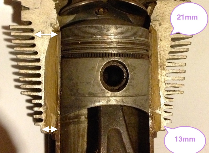
The cylinder casting has variable wall thicknesses, and is much thicker at the top of the liner than it is at the base of the casting, which means for any given interference fit, the base of the casting will give more than the top, so the liner is squeezed prorate more at the top than the bottom.
Really simple and it’s just physics. By varying the wall thickness to suit the likely temperature gradient, you can achieve tighter running clearances by tapering the bore inwards when cold. If this is combined with modern piston technology & manufacturing a quieter, more powerful air cooled engine will be the result.
A Panhard air cooled twin has tapered bores, but the cylinder casting internal bore is parallel, the liner or sleeve is parallel externally, and all the new old stock liners have been as near as damn it parallel internally. So what is causing the taper?
Here’s the answer
The cylinder casting has variable wall thicknesses, and is much thicker at the top of the liner than it is at the base of the casting, which means for any given interference fit, the base of the casting will give more than the top, so the liner is squeezed prorate more at the top than the bottom.
Really simple and it’s just physics. By varying the wall thickness to suit the likely temperature gradient, you can achieve tighter running clearances by tapering the bore inwards when cold. If this is combined with modern piston technology & manufacturing a quieter, more powerful air cooled engine will be the result.
