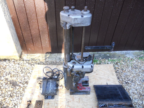
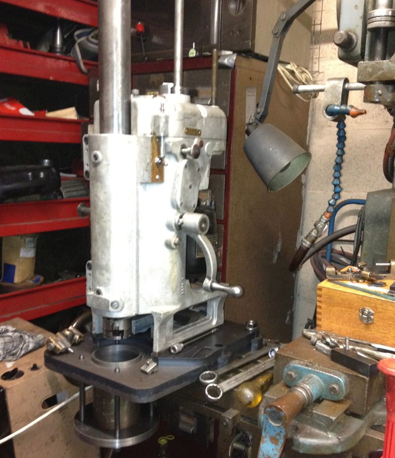
This is the raw casting, without motor or boring bar fitted. It is being cleaned and refurbished at the moment, but you might notice it is essentially an aluminium casting with cast in steel soleplate. They were usually painted in two or more colours, but I have decided to strip it back to bare aluminium.
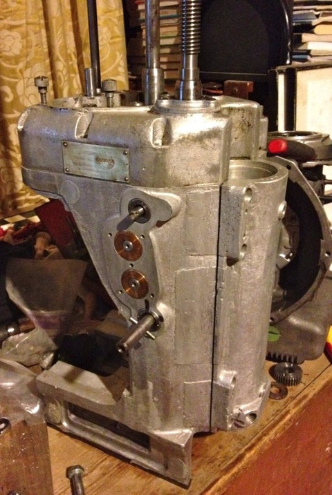
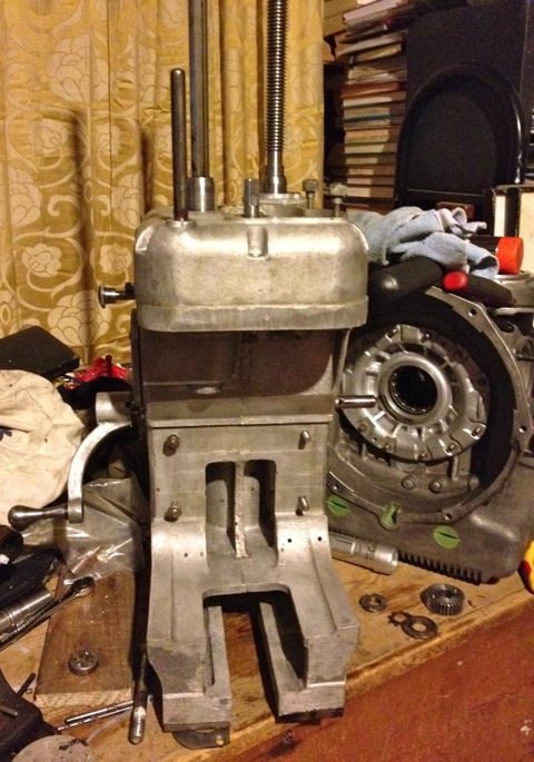
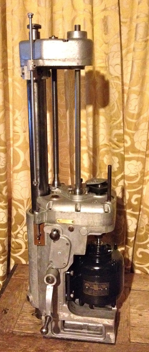
It normally has a 1400 rpm AEI motor fitted, usually 240V single phase and around 1/4 horsepower or 180W. The original motor needs a rewind, but hopefully over the next few days I might find another one in good condition.
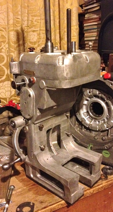
I also need some imperial woodruff keys for the change wheel motor gears, various Whitworth fasteners, and make a few shims on the lathe to finish it off. The gearbox is all functioning properly, so I now have a smoothly selectable two speed feed rate and a cog swapping two speed boring head tip speed function, which is needed as the boring bar covers 2.2”-4.2” diameter bores, and the tip speed would be too high at the larger sizes if it was just one speed.
UPDATE Easter 2012
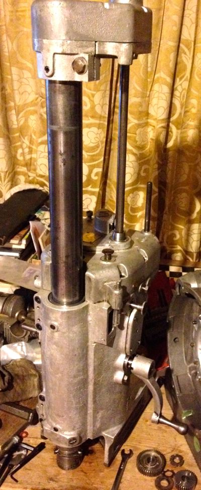
The woodruff keys have arrived, and I have built the Whatton up some more. The detailing on it is very good, but there is hardly any real info on the web. I am in the process of sorting out the toolkit and doing the research on Wimet tool tips. This boring bar takes 5/16” TCT bar, which is about 3/4” long, and I am trying to identify whether it was a standard design. The Van Norman took 1/4” tooltips, and I have found some of these on eBay, but it’ll probably be worthwhile making a indexable tip version, to facilitate easier replacement stock.
I managed to acquire a Wimet catalogue from the 1970s, and it seems I might be able to mod some round bar 90º tool stock.
The standard Whatton toolkit came with a diamond encrusted wheel, that was encased in bakelite, and was called a Spedia, which was similar to a Neven product from what I have read so far. They don’t exist anymore as such, but I am trying to see if I can get the wheel recoated. There was also a jig to make refacing the tooltip an easy four step operation.
This is the small tooltip holder, which covers from 2.2”-3.3”, and there is a larger one that does the bigger sizes. The lower limit is the size of the boring bar, which is around 54mm, and the upper limit will be the tooltip length in the large holder, although to get it centred, it might need additional rods for the three point centring tool, as these only reach to 3.6” at the moment. The boring bar should reach 4.2” comfortably, so I am unsure why there is such a large discrepancy here, but it is possible there is something missing or not quite built up properly.
The micrometer clamps to the bar head with a patentable mechanism, as shown.
The operator sets the micrometer to the desired bore
and winds the tooltip to just touch the end of the micrometer.
With my tooltips in place in their holders, I have a diametric range of 54-84mm, and 87-105mm, so as I am looking for 85.5mm, I will need to swap the slightly shorter tool tip into the large toolholder and vice versa. Below are the two remaining Wimet tooltips I have left, which are in good condition.
These are their respective tool-holders
Some idea of the variation in size.
This gives a range of 81-107mm from the small tooltip in the longer toolholder, which comfortably covers my requirements for the Panhard rebore, which is at 85.51mm.
However a range of 61-96 mm from the longer tip in the smaller holder is also possible, which also covers the Panhard rebore sizes too, but I might be able to reduce the lower limit further as the toolholder adjuster catches the base of the micrometer fixture. If it is chamfered slightly this should add another 2mm or so, which also infers that altering the overall length of the tooltip will allow for further variations in bore sizes to be achieved, and I think a bespoke indexable tool that mimics the toolholder could extend the usefulness of this Boring Bar even further.
UPDATE 8 April 2012
The back of the toolholder has now been chamfered, and the smallest diameter bore I can achieve with the long tipped bit in the short toolholder is 58.7mm, so a gain of just over 2mm has been achieved.By the way, the small tip in the short holder will actually do less than 2.2” using this modified part, which means I can possibly rebore 125cc kart, or 600cc four cylinder engines too.
Hopefully I will pick up the motor next week, plus the stainless steel 1/4” rod will have arrived, and then I can rewire the Whatton and restore the mechanical cut off feature at the on/off switch. I am also thinking of putting a resettable overload device in the motor wiring cover plate, just in case it stalls on the way up, because I am thinking of making the motor reverse too and this will give a motorised power up for boring bar removal. It would save messing with the gear selector on the side, because at the moment you select the middle position and disengage the motor drive gears and manually wind it up, although using a powered feed means you’d better wind the cutting head back in, otherwise you’d score the bores on the way out!
UPDATE 14 April 2012
I managed to pick up the motor this week, and it does have the same size output shaft, and plate dimensions, however I need to make a motor spacer to align the motor to gearbox shafts, before I can get it running. The newer AEI motor has an updated bearing layout, but it is still quite an old version, circa 1964, which was taken from a Hunter Penrose vacuum pump, that was installed in an old photographic shop. I have wired the motor up and left it running for 10 minutes under no load. The motor has a centrifugal start mechanism inside, and doesn’t get warm or smell cooked, so it’s looking good.
The stainless rod also dropped through the post box, so I made a few bobbins on the lathe, and threaded the ends of the rod to make a new safety bar/mechanical cut off switch. I’m locking the position with an Allen headed socket set screw, but ideally it should be a knurled wheel or similar, so I’ll have to make one of those next weekend, but only if I manage to get hold of a cross knurling double wheel tool for the lathe.
I checked the original motor rotation, but the new motor spins the opposite way and will need reversing. Instructions on how to do this are under the motor wiring cover plate, and I just swapped the internal motor wires over, so A1goes to A2 & A2 to A1, and in doing so I noticed the motor had been reversed for the vacuum pump application.
After testing the switch operation, I made a wiring loom, using spade connectors and eyelets, and fitted the motor to the boring bar, and it looks like this at the moment, but it’s going to get cleaned up and painted silver or black. The white electrical wire was the only four core I had, and I think I’ll change this for a black one later.
I have just given it another test run in situ, and had a play with the boring bar grinding/lapping jig. Works really well, with just some temporary washers acting as a spacer, but tightening the motor down changes the noise, so I am going to shim this for quietest running, once I get the new laser cut spacer.
UPDATE 21 APRIL 2012
I am still waiting for the laser cut spacer, but I have cleaned the motor and given it a lick of paint. Everything seems to be working very well, and I have lubricated the bearings and gears, which has made the machine a little quieter.
Pictures are a little soft, used the iPhone again.
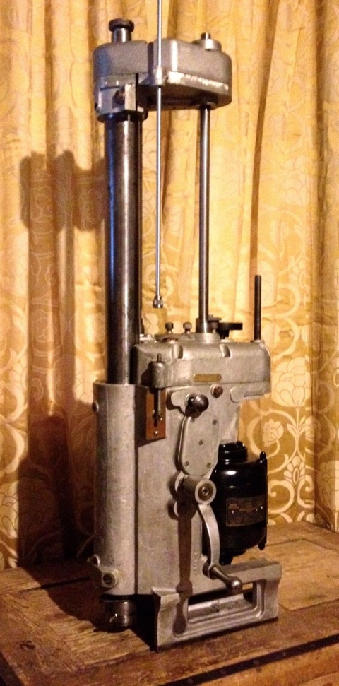
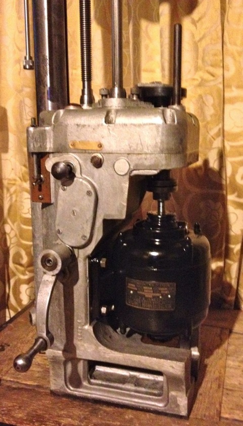
In this picture you can see the on/off switch middle left, and above it the bar that knocks the switch off at a predetermined depth. Motor was taken off a vacuum pump, that is settling in to its’ reverse rotation, and I have noticed it is a lot more powerful than the tired unit that was on the Whatton before, which you can see bottom left in the picture below. I am quite pleased with the overall transformation so far, and having worked on the internals, this boring bar has definitely been given a new lease of life. Fortunately the original motor was in such a weakened state it wasn’t able to destroy the gearboxes inside, just itself when it stalled.
Next up, CAD up a plate to sit the boring bar on, and machine it to take a Panhard liner, although I am thinking of making a set of concentric sleeves/adapters to give the table greater flexibility. I also have to sort out some new tool tips.
UPDATE 22 April 2012
I bought these longer bits from the USA, but they are not really suitable, as I have to machine a new flat on them. You can see the carbide face is 90 degrees out.
I have seen a couple of companies make carbide tips, so I have drawn one up in CAD, as shown below, and hopefully I can get a quote on some new ones. The plan B is to get some solid carbide tool stock, and make them myself, but it’d be nice to swap them out or have new stock available.
Obviously the other option is make an adaptor for indexable tooling, and just buy standard CNMT tips, a bit like this.
UPDATE 6 August 2012
Finally managed to machine the support plate for the cylinder liner to the right size. The lathe wasn’t able to do it, so I used the Whatton boring machine. Unfortunately, the Whatton really struggled with the work hardened laser cut plate, and the tooltips got hammered, but finally it was done.
The cylinder liner can now be held in situ, whilst it’s being rebored.
Everything is almost working OK, but I need to refine the belt tension, and the tooltip selection. I think I need to convert the Whatton to indexable tooling, as well as look at the pulley & V belt some more, as the tooltip can stall in the bore with a heavier cut.
Update 23 September 2012
I recently bought an upgraded version of the original motor off eBay, a 370W or 1/2 horsepower with the correct baseplate. However when I tried to swap the motor over today, I discovered the increased height or length didn’t allow it to clear the main casting. I had to revert back to the old motor, but I did use the cush drive off the vacuum pump, which was more concentric than the old part, and the boring machine is much quieter, with less vibration.
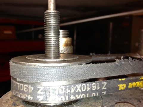
I have been doing all the attempted cuts so far with a single belt, and really struggled to fit one belt let alone the two that are required. Today I managed to fit the sister belt, a Z16 428 Ld, 410 Li onto the double fee pulley. It was at this point I notice the other belt was slightly stretched and greasy. The frayed edges are a result of a woodruff key being fitted incorrectly by the previous owner, it should never had one, as it had a hardened circular pin, that located in a vertical keyway. The woodruff key grabbed and wore itself out, and caused the belt to run at an angle, so cutting the edges.
I cannot guarantee I will get the same, so I have ordered two new belts to replace the stretched one. I also have a novel way (new to me) of getting the vee belt onto the pulleys, which doesn’t involve taking the pulleys off and sliding them down the shafts, however I cannot tell you how, as it might mean a silly person could lose a finger. Suffice to say, I cannot turn the pulleys by hand to get the belt to fall into its respective groove without it needing some electrical assistance.
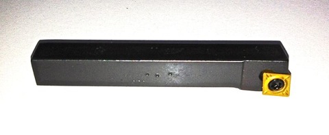
The tooltips were scheduled to be done today, but I am pleased they haven’t been done yet as I have bought another LH boring tool to convert, and so I don’t have to pay for another set up charge.
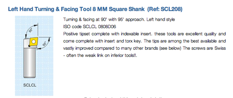
It’s 8mm square shanked, indexable and takes CCMT inserts, but I am having it shortened and made 5/16” round with a flat put on it to lock it off square in the boring head tooltip carrier.
Hopefully, I will be able to use them soon, within the first week of October, in the boring machine, and then get the test liner analysed for surface finish, squareness etc at the local engineering works. If all works out, I will be able to rebore Panhard liners in the future to very precise standards.
Update 29 September 2012
Today I collected the tooltips that I had modified, and also fitted the vee belts, that had arrived in the post earlier in the week, to the Whatton Boring Bar. After struggling to get them onto the pulleys, and replacing the top cover, I fitted a new indexable tips to the short tool tip holder.
I centralised the bar over the liner and went to adjust the tip using the micrometer, and discovered the tooltip was not catching the micrometer anvil, because it cuts slightly lower now it misses the anvil tip. I will have to make a larger diameter adaptor to sleeve & cap over the anvil of the micrometer, which might add say 0.1” thick overall externally, to make reading the actual size easier. A bit of machined silvered steel to the rescue, aided by a helpful chap on a tool grinder down the road.
If you look at the picture above you can see the cutting edge is much lower than the centre line of the old carbide tip.
This is the 12mm square shank tool converted in the long holder with a 8mm square shanked version in the background. The original tip is in the foreground.
I started to machine the liner, and the motor never stalled at all, so finally a little success, and the first shallow cut was of a very good surface finish. Next I tried a slower roughing cut, and after about halfway down the liner, some strange swishing/grating noises started to reverberate from the bar. I couldn’t see what was happening, as the heavier cut was creating a fair amount of dust, (note to me, need a vacuum source to remove cutting dust). When I looked at the bore after the cutting process had finished, I had a perfect bore for about half the length of the liner, then a series of ridges or ringed undulations. :eek
I had to leave off at that point and sort out a few other jobs, but it would appear the back edge of the tooltip was catching the bore, which is easily remedied by grinding an increased taper behind the tooltip face, but more importantly & slightly worrying is the only way it could ring the bore was if the tooltip was moving. I am going to try with the longer tooltip holder to see if the short tool holder was rocking slightly, and therefore pushing into the liner. I will also double check the gigs that take up the play on the bar as it travels downwards. The latter wasn’t an issue before, but I have to check.
Anyway I am pleased that the motor/tooltip stall with the original carbide tipped tools isn’t repeating itself, just got to work on this new problem.
Update 7 October 2012
Yet again, I could only manage a few hours on the Panhard stuff, but I have finally cured the machining issues I had reboring the liners.
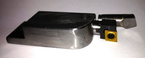
This is the set up as it stands now, long tooltip holder, modified LH boring bar with indexable CCMT insert, but unfortunately the longer tooltip holder fouls the boring bar micrometer body, so I cannot take a direct measurement using it at the moment. A little tweak with a Dremel should solve this, but I’ll do it another day, when I make a sleeve for the anvil, so it contacts the lower cutting surface of the new indexable insert.
On examination the bore was truly round, had a good consistent surface finish and measured 86.03 mm at the top, middle and bottom. I have eliminated the chatter that caused the rippling to the bore last weekend, by using the larger tooltip holder, but I got a slight scoring at three points afterwards. However, a slower feed speed, as well as tightening the spring loaded gibs, and increasing the pressure on the boring bar sleeves to eliminate the sliding play stopped any further occurrences.
Interestingly the original induction motor runs lot cooler with the vacuum pump motor coupling, which has a rubber cush drive rather than a leather or felt pad, and even with the increased loadings and therefore additional effort required to move the boring bar ,through the slides, there is no increase in temperature.
The ripple to the bores was caused by me inadvertently using the shorter tooltip holder, which is really made for the smaller bores sizes. The grub screw which is designed to lock the tooltip holder in position, was in fact gripping the adjusting plate, and so the tooltip holder was vibrating and moving on the screw adjuster.
Considering I didn’t have a manual, or know of any other person with one of these, losing just one liner to teething issues is a good result.
Here is the test cylinder after honing, but not washed yet though.
Update 13 October 2012
One of the areas I had to improve was the direct reading of the Whatton Boring Bar now that I have converted it to some readily available indexable tooltips.
The dedicated micrometer was not touching the tooltip, because the tooltip was lower than the anvil. A few moments on the lathe to test the idea, and bingo.
Here it is in situ, that’s attached to the anvil, with the micrometer fixed to the boring bar.
I just have to set the tip position and to do another test bore to establish the actual bore size measured by the three point bore micrometer versus the indicated reading of the Whatton micrometer.
Update 27 October 2012
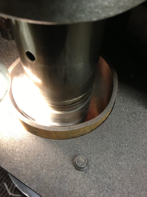
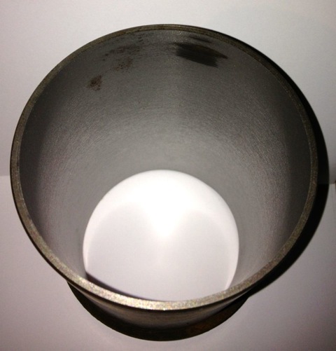
Using the freshly extracted & cooled cylinder liners from today, I loaded one into the Whatton boring machine jig, and started to centralise the Whatton to the liner. I usually drop the bar into the liner, centralise the machine using the three point cats paws, and tighten the base onto the mill bed.
I decided on an arbitrary test bore of 3.353” for the first cut, which is approximately 85.1mm, and just a bit oversize on the original liners.
I then started to machine the liner, but I noticed that the cut was greater on one side and not removing material from the opposite side, so I decided to recenter the Whatton at the top of the liner held in the rig. This is actually the bottom of the liner in reality...
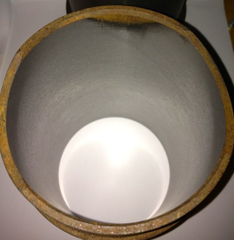
You can see the slight ring at the top in this picture above, when I centred the liner at the top of rig, and in the picture below, the area missed in the machining.
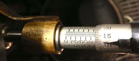
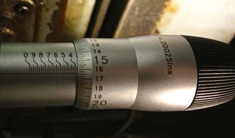
Obviously, further machining is required, but whether it will remove this blemish inside the liner is not known until you try, so it’s time to reset the cutting tip and see if cutting a slightly larger diameter will do it. New diameter is set at 3.3665”, as shown below, by sliding the tooltip out towards the micrometer.
and then after tightening the tooltip locking screw, a quick recheck, but there’s not much difference here, about a thou, so it’s now reading 3.3655” as shown below.
Notice how the top step is taken out by machining a larger diameter, but what will happen later on?
So when the second cut is finished, I let the tooltip pass through the liner & bottom mounting plate, and recheck the tooltip bore diameter, which hasn’t changed and reads 3.3655”. All is looking good.
However a quick check with the Bowers imperial three point micrometer reveals the actual bore measurement is 3.3614”, so the Whatton is reading about 0.004” oversize.
It’s still a good result, as I can now calibrate the Whatton micrometer to the actual bore size by resetting the detent. Incidentally the wear wasn’t quite machined out of the bottom part of the liner, (top in the picture below), but as it was less than 0.0005” on diameter when measured, the final cross hatch & prior honing process will remove this comfortably.
I decided to test the calibration by machining the other liner, but this time centre the Whatton with the bottom of the rig, as I originally started to do with the above liner. This left a very slight un-machined area at the top of the liner, which is really the bottom. No rings operate in this area, so it’s not critical, but either way it will be removed by the final honing process too.
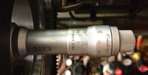
This second liner was machined at just under 3.366” using the Whatton direct reading micrometer, but after boring it measured 85.500mm with the three point Mitutoyo, and 3.3663” using the Bowers, so it’s well within my operating parameters.
A good days work, next up, reinstall the liners, and check the finished diameters, so the true clearance can be established or continue to test hone the cylinder liners using the Delapena hone. For the latter, I will have to CAD up a drawing, as I need to make a rig to hold the liners, before I can hone them properly. It’s not worth using the Whatton set up, as it’ll be too much disruption.
It normally has a 1400 rpm AEI motor fitted, usually 240V single phase and around 1/4 horsepower or 180W. The original motor needs a rewind, but hopefully over the next few days I might find another one in good condition.
I also need some imperial woodruff keys for the change wheel motor gears, various Whitworth fasteners, and make a few shims on the lathe to finish it off. The gearbox is all functioning properly, so I now have a smoothly selectable two speed feed rate and a cog swapping two speed boring head tip speed function, which is needed as the boring bar covers 2.2”-4.2” diameter bores, and the tip speed would be too high at the larger sizes if it was just one speed.
UPDATE Easter 2012
The woodruff keys have arrived, and I have built the Whatton up some more. The detailing on it is very good, but there is hardly any real info on the web. I am in the process of sorting out the toolkit and doing the research on Wimet tool tips. This boring bar takes 5/16” TCT bar, which is about 3/4” long, and I am trying to identify whether it was a standard design. The Van Norman took 1/4” tooltips, and I have found some of these on eBay, but it’ll probably be worthwhile making a indexable tip version, to facilitate easier replacement stock.
I managed to acquire a Wimet catalogue from the 1970s, and it seems I might be able to mod some round bar 90º tool stock.
The standard Whatton toolkit came with a diamond encrusted wheel, that was encased in bakelite, and was called a Spedia, which was similar to a Neven product from what I have read so far. They don’t exist anymore as such, but I am trying to see if I can get the wheel recoated. There was also a jig to make refacing the tooltip an easy four step operation.
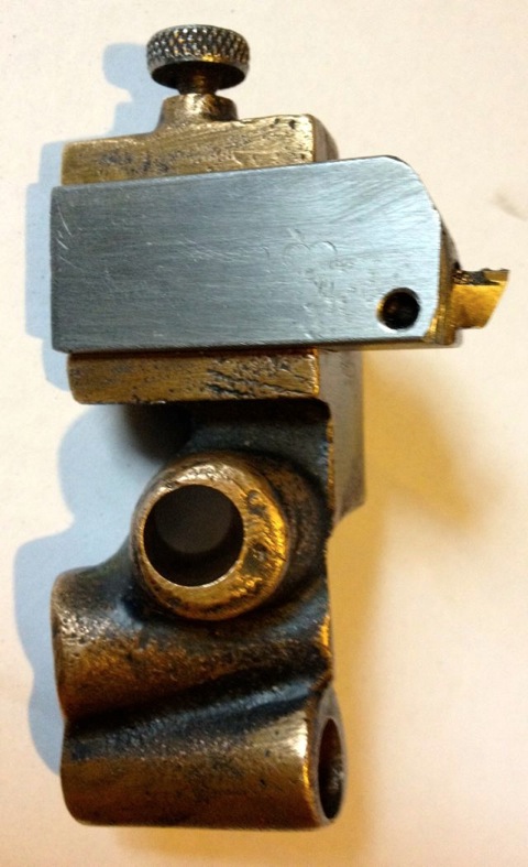
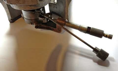
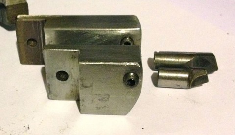
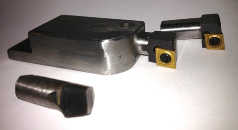
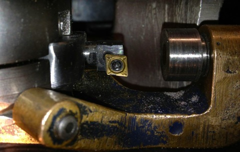
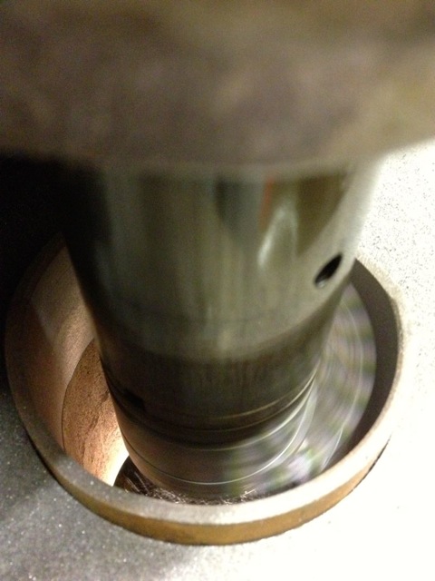
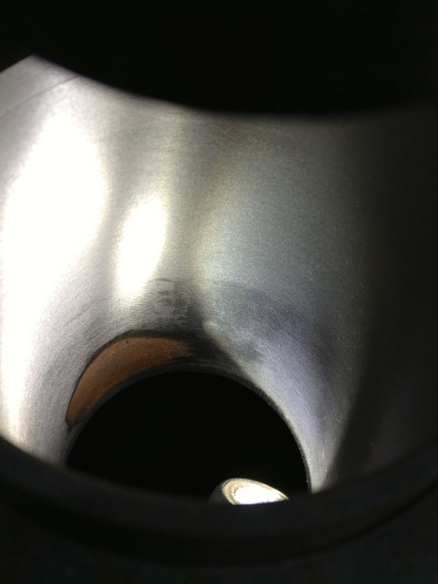
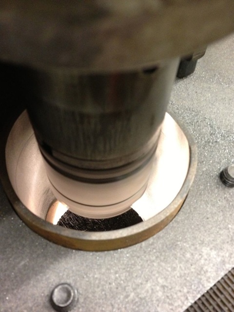
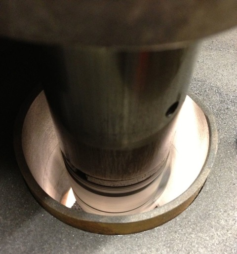
This is the small tooltip holder, which covers from 2.2”-3.3”, and there is a larger one that does the bigger sizes. The lower limit is the size of the boring bar, which is around 54mm, and the upper limit will be the tooltip length in the large holder, although to get it centred, it might need additional rods for the three point centring tool, as these only reach to 3.6” at the moment. The boring bar should reach 4.2” comfortably, so I am unsure why there is such a large discrepancy here, but it is possible there is something missing or not quite built up properly.
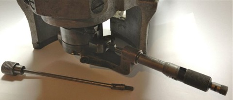
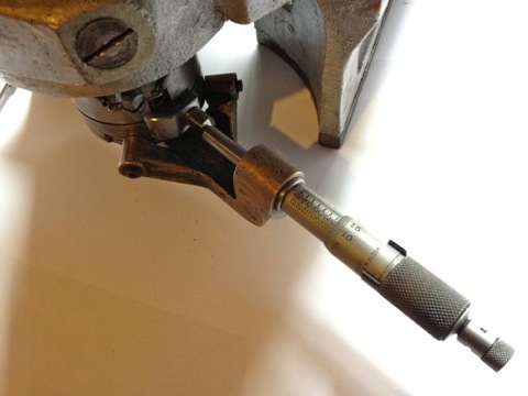
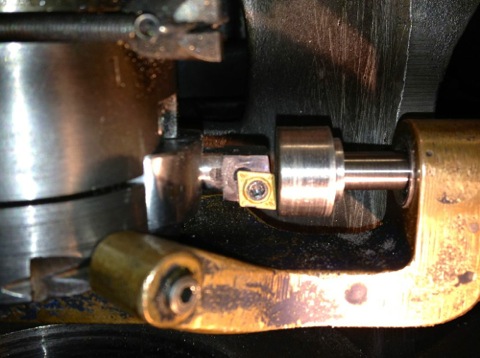
The micrometer clamps to the bar head with a patentable mechanism, as shown.
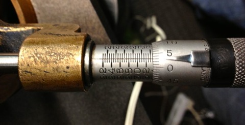
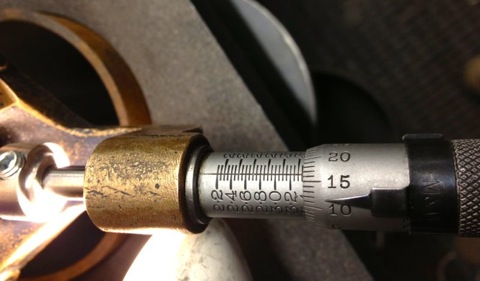
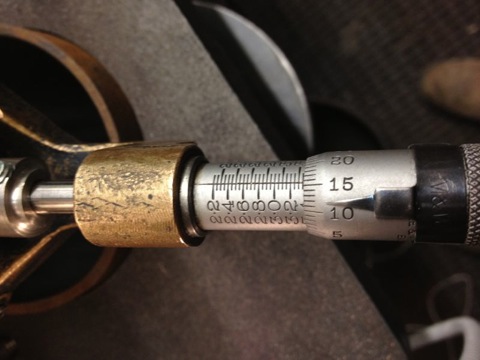
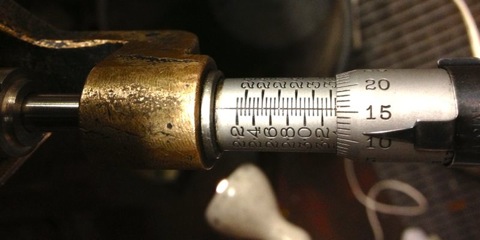
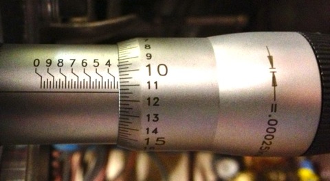
The operator sets the micrometer to the desired bore
and winds the tooltip to just touch the end of the micrometer.
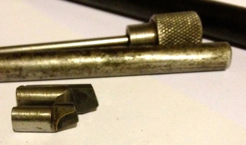
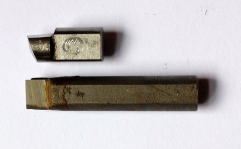
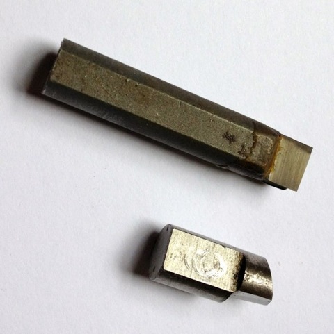
With my tooltips in place in their holders, I have a diametric range of 54-84mm, and 87-105mm, so as I am looking for 85.5mm, I will need to swap the slightly shorter tool tip into the large toolholder and vice versa. Below are the two remaining Wimet tooltips I have left, which are in good condition.
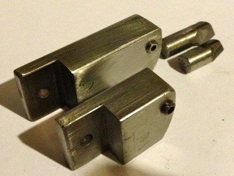
These are their respective tool-holders
Some idea of the variation in size.
This gives a range of 81-107mm from the small tooltip in the longer toolholder, which comfortably covers my requirements for the Panhard rebore, which is at 85.51mm.
However a range of 61-96 mm from the longer tip in the smaller holder is also possible, which also covers the Panhard rebore sizes too, but I might be able to reduce the lower limit further as the toolholder adjuster catches the base of the micrometer fixture. If it is chamfered slightly this should add another 2mm or so, which also infers that altering the overall length of the tooltip will allow for further variations in bore sizes to be achieved, and I think a bespoke indexable tool that mimics the toolholder could extend the usefulness of this Boring Bar even further.
UPDATE 8 April 2012
The back of the toolholder has now been chamfered, and the smallest diameter bore I can achieve with the long tipped bit in the short toolholder is 58.7mm, so a gain of just over 2mm has been achieved.By the way, the small tip in the short holder will actually do less than 2.2” using this modified part, which means I can possibly rebore 125cc kart, or 600cc four cylinder engines too.
Hopefully I will pick up the motor next week, plus the stainless steel 1/4” rod will have arrived, and then I can rewire the Whatton and restore the mechanical cut off feature at the on/off switch. I am also thinking of putting a resettable overload device in the motor wiring cover plate, just in case it stalls on the way up, because I am thinking of making the motor reverse too and this will give a motorised power up for boring bar removal. It would save messing with the gear selector on the side, because at the moment you select the middle position and disengage the motor drive gears and manually wind it up, although using a powered feed means you’d better wind the cutting head back in, otherwise you’d score the bores on the way out!
UPDATE 14 April 2012
I managed to pick up the motor this week, and it does have the same size output shaft, and plate dimensions, however I need to make a motor spacer to align the motor to gearbox shafts, before I can get it running. The newer AEI motor has an updated bearing layout, but it is still quite an old version, circa 1964, which was taken from a Hunter Penrose vacuum pump, that was installed in an old photographic shop. I have wired the motor up and left it running for 10 minutes under no load. The motor has a centrifugal start mechanism inside, and doesn’t get warm or smell cooked, so it’s looking good.
The stainless rod also dropped through the post box, so I made a few bobbins on the lathe, and threaded the ends of the rod to make a new safety bar/mechanical cut off switch. I’m locking the position with an Allen headed socket set screw, but ideally it should be a knurled wheel or similar, so I’ll have to make one of those next weekend, but only if I manage to get hold of a cross knurling double wheel tool for the lathe.
I checked the original motor rotation, but the new motor spins the opposite way and will need reversing. Instructions on how to do this are under the motor wiring cover plate, and I just swapped the internal motor wires over, so A1goes to A2 & A2 to A1, and in doing so I noticed the motor had been reversed for the vacuum pump application.
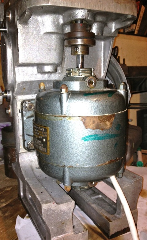
After testing the switch operation, I made a wiring loom, using spade connectors and eyelets, and fitted the motor to the boring bar, and it looks like this at the moment, but it’s going to get cleaned up and painted silver or black. The white electrical wire was the only four core I had, and I think I’ll change this for a black one later.
I have just given it another test run in situ, and had a play with the boring bar grinding/lapping jig. Works really well, with just some temporary washers acting as a spacer, but tightening the motor down changes the noise, so I am going to shim this for quietest running, once I get the new laser cut spacer.
UPDATE 21 APRIL 2012
I am still waiting for the laser cut spacer, but I have cleaned the motor and given it a lick of paint. Everything seems to be working very well, and I have lubricated the bearings and gears, which has made the machine a little quieter.
Pictures are a little soft, used the iPhone again.
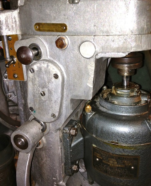
In this picture you can see the on/off switch middle left, and above it the bar that knocks the switch off at a predetermined depth. Motor was taken off a vacuum pump, that is settling in to its’ reverse rotation, and I have noticed it is a lot more powerful than the tired unit that was on the Whatton before, which you can see bottom left in the picture below. I am quite pleased with the overall transformation so far, and having worked on the internals, this boring bar has definitely been given a new lease of life. Fortunately the original motor was in such a weakened state it wasn’t able to destroy the gearboxes inside, just itself when it stalled.
Next up, CAD up a plate to sit the boring bar on, and machine it to take a Panhard liner, although I am thinking of making a set of concentric sleeves/adapters to give the table greater flexibility. I also have to sort out some new tool tips.
UPDATE 22 April 2012
I bought these longer bits from the USA, but they are not really suitable, as I have to machine a new flat on them. You can see the carbide face is 90 degrees out.
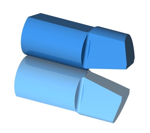
I have seen a couple of companies make carbide tips, so I have drawn one up in CAD, as shown below, and hopefully I can get a quote on some new ones. The plan B is to get some solid carbide tool stock, and make them myself, but it’d be nice to swap them out or have new stock available.
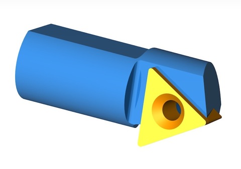
Obviously the other option is make an adaptor for indexable tooling, and just buy standard CNMT tips, a bit like this.
UPDATE 6 August 2012
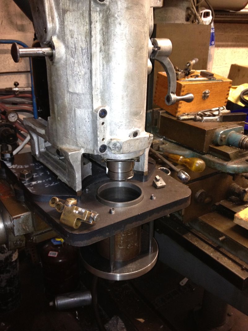
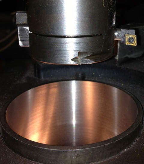
Finally managed to machine the support plate for the cylinder liner to the right size. The lathe wasn’t able to do it, so I used the Whatton boring machine. Unfortunately, the Whatton really struggled with the work hardened laser cut plate, and the tooltips got hammered, but finally it was done.
The cylinder liner can now be held in situ, whilst it’s being rebored.
Everything is almost working OK, but I need to refine the belt tension, and the tooltip selection. I think I need to convert the Whatton to indexable tooling, as well as look at the pulley & V belt some more, as the tooltip can stall in the bore with a heavier cut.
Update 23 September 2012
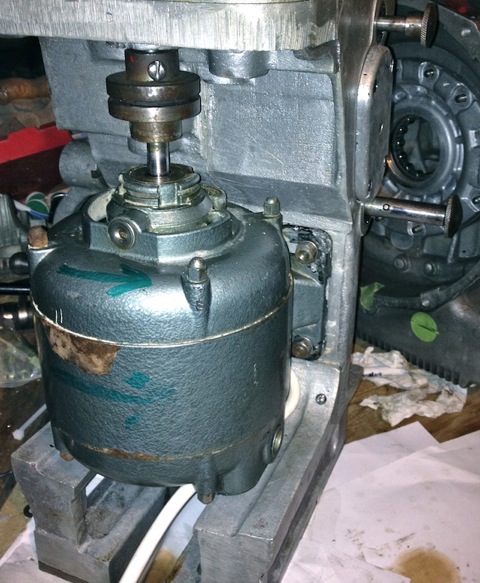
I recently bought an upgraded version of the original motor off eBay, a 370W or 1/2 horsepower with the correct baseplate. However when I tried to swap the motor over today, I discovered the increased height or length didn’t allow it to clear the main casting. I had to revert back to the old motor, but I did use the cush drive off the vacuum pump, which was more concentric than the old part, and the boring machine is much quieter, with less vibration.
I have been doing all the attempted cuts so far with a single belt, and really struggled to fit one belt let alone the two that are required. Today I managed to fit the sister belt, a Z16 428 Ld, 410 Li onto the double fee pulley. It was at this point I notice the other belt was slightly stretched and greasy. The frayed edges are a result of a woodruff key being fitted incorrectly by the previous owner, it should never had one, as it had a hardened circular pin, that located in a vertical keyway. The woodruff key grabbed and wore itself out, and caused the belt to run at an angle, so cutting the edges.
I cannot guarantee I will get the same, so I have ordered two new belts to replace the stretched one. I also have a novel way (new to me) of getting the vee belt onto the pulleys, which doesn’t involve taking the pulleys off and sliding them down the shafts, however I cannot tell you how, as it might mean a silly person could lose a finger. Suffice to say, I cannot turn the pulleys by hand to get the belt to fall into its respective groove without it needing some electrical assistance.
The tooltips were scheduled to be done today, but I am pleased they haven’t been done yet as I have bought another LH boring tool to convert, and so I don’t have to pay for another set up charge.
It’s 8mm square shanked, indexable and takes CCMT inserts, but I am having it shortened and made 5/16” round with a flat put on it to lock it off square in the boring head tooltip carrier.
Hopefully, I will be able to use them soon, within the first week of October, in the boring machine, and then get the test liner analysed for surface finish, squareness etc at the local engineering works. If all works out, I will be able to rebore Panhard liners in the future to very precise standards.
Update 29 September 2012
Today I collected the tooltips that I had modified, and also fitted the vee belts, that had arrived in the post earlier in the week, to the Whatton Boring Bar. After struggling to get them onto the pulleys, and replacing the top cover, I fitted a new indexable tips to the short tool tip holder.
I centralised the bar over the liner and went to adjust the tip using the micrometer, and discovered the tooltip was not catching the micrometer anvil, because it cuts slightly lower now it misses the anvil tip. I will have to make a larger diameter adaptor to sleeve & cap over the anvil of the micrometer, which might add say 0.1” thick overall externally, to make reading the actual size easier. A bit of machined silvered steel to the rescue, aided by a helpful chap on a tool grinder down the road.
If you look at the picture above you can see the cutting edge is much lower than the centre line of the old carbide tip.
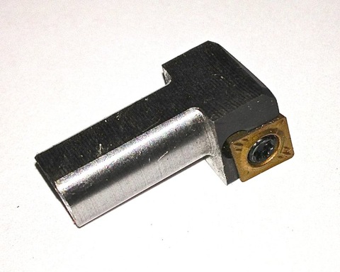
This is the 12mm square shank tool converted in the long holder with a 8mm square shanked version in the background. The original tip is in the foreground.
I started to machine the liner, and the motor never stalled at all, so finally a little success, and the first shallow cut was of a very good surface finish. Next I tried a slower roughing cut, and after about halfway down the liner, some strange swishing/grating noises started to reverberate from the bar. I couldn’t see what was happening, as the heavier cut was creating a fair amount of dust, (note to me, need a vacuum source to remove cutting dust). When I looked at the bore after the cutting process had finished, I had a perfect bore for about half the length of the liner, then a series of ridges or ringed undulations. :eek
I had to leave off at that point and sort out a few other jobs, but it would appear the back edge of the tooltip was catching the bore, which is easily remedied by grinding an increased taper behind the tooltip face, but more importantly & slightly worrying is the only way it could ring the bore was if the tooltip was moving. I am going to try with the longer tooltip holder to see if the short tool holder was rocking slightly, and therefore pushing into the liner. I will also double check the gigs that take up the play on the bar as it travels downwards. The latter wasn’t an issue before, but I have to check.
Anyway I am pleased that the motor/tooltip stall with the original carbide tipped tools isn’t repeating itself, just got to work on this new problem.
Update 7 October 2012
Yet again, I could only manage a few hours on the Panhard stuff, but I have finally cured the machining issues I had reboring the liners.
This is the set up as it stands now, long tooltip holder, modified LH boring bar with indexable CCMT insert, but unfortunately the longer tooltip holder fouls the boring bar micrometer body, so I cannot take a direct measurement using it at the moment. A little tweak with a Dremel should solve this, but I’ll do it another day, when I make a sleeve for the anvil, so it contacts the lower cutting surface of the new indexable insert.
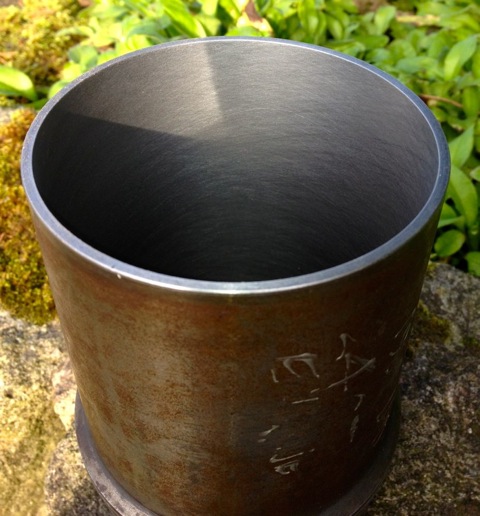
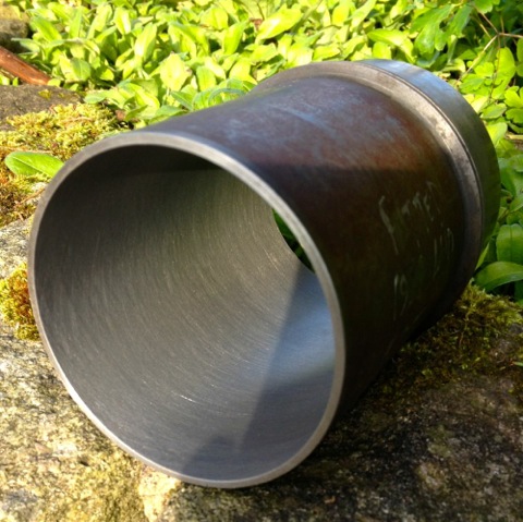
On examination the bore was truly round, had a good consistent surface finish and measured 86.03 mm at the top, middle and bottom. I have eliminated the chatter that caused the rippling to the bore last weekend, by using the larger tooltip holder, but I got a slight scoring at three points afterwards. However, a slower feed speed, as well as tightening the spring loaded gibs, and increasing the pressure on the boring bar sleeves to eliminate the sliding play stopped any further occurrences.
Interestingly the original induction motor runs lot cooler with the vacuum pump motor coupling, which has a rubber cush drive rather than a leather or felt pad, and even with the increased loadings and therefore additional effort required to move the boring bar ,through the slides, there is no increase in temperature.
The ripple to the bores was caused by me inadvertently using the shorter tooltip holder, which is really made for the smaller bores sizes. The grub screw which is designed to lock the tooltip holder in position, was in fact gripping the adjusting plate, and so the tooltip holder was vibrating and moving on the screw adjuster.
Considering I didn’t have a manual, or know of any other person with one of these, losing just one liner to teething issues is a good result.
Here is the test cylinder after honing, but not washed yet though.
Update 13 October 2012
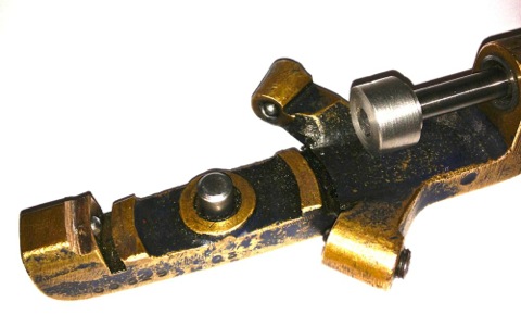
One of the areas I had to improve was the direct reading of the Whatton Boring Bar now that I have converted it to some readily available indexable tooltips.
The dedicated micrometer was not touching the tooltip, because the tooltip was lower than the anvil. A few moments on the lathe to test the idea, and bingo.
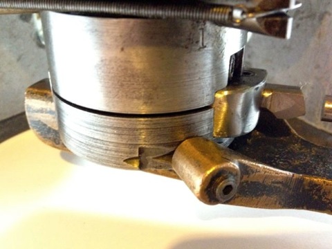
Here it is in situ, that’s attached to the anvil, with the micrometer fixed to the boring bar.
I just have to set the tip position and to do another test bore to establish the actual bore size measured by the three point bore micrometer versus the indicated reading of the Whatton micrometer.
Update 27 October 2012
Using the freshly extracted & cooled cylinder liners from today, I loaded one into the Whatton boring machine jig, and started to centralise the Whatton to the liner. I usually drop the bar into the liner, centralise the machine using the three point cats paws, and tighten the base onto the mill bed.
I decided on an arbitrary test bore of 3.353” for the first cut, which is approximately 85.1mm, and just a bit oversize on the original liners.
I then started to machine the liner, but I noticed that the cut was greater on one side and not removing material from the opposite side, so I decided to recenter the Whatton at the top of the liner held in the rig. This is actually the bottom of the liner in reality...
You can see the slight ring at the top in this picture above, when I centred the liner at the top of rig, and in the picture below, the area missed in the machining.
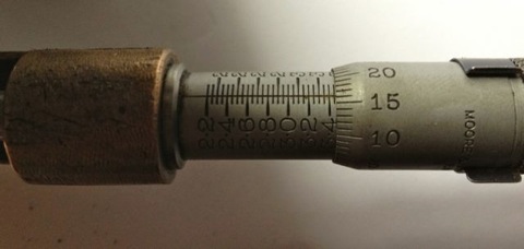
Obviously, further machining is required, but whether it will remove this blemish inside the liner is not known until you try, so it’s time to reset the cutting tip and see if cutting a slightly larger diameter will do it. New diameter is set at 3.3665”, as shown below, by sliding the tooltip out towards the micrometer.
and then after tightening the tooltip locking screw, a quick recheck, but there’s not much difference here, about a thou, so it’s now reading 3.3655” as shown below.
Notice how the top step is taken out by machining a larger diameter, but what will happen later on?
So when the second cut is finished, I let the tooltip pass through the liner & bottom mounting plate, and recheck the tooltip bore diameter, which hasn’t changed and reads 3.3655”. All is looking good.
However a quick check with the Bowers imperial three point micrometer reveals the actual bore measurement is 3.3614”, so the Whatton is reading about 0.004” oversize.
It’s still a good result, as I can now calibrate the Whatton micrometer to the actual bore size by resetting the detent. Incidentally the wear wasn’t quite machined out of the bottom part of the liner, (top in the picture below), but as it was less than 0.0005” on diameter when measured, the final cross hatch & prior honing process will remove this comfortably.
I decided to test the calibration by machining the other liner, but this time centre the Whatton with the bottom of the rig, as I originally started to do with the above liner. This left a very slight un-machined area at the top of the liner, which is really the bottom. No rings operate in this area, so it’s not critical, but either way it will be removed by the final honing process too.
This second liner was machined at just under 3.366” using the Whatton direct reading micrometer, but after boring it measured 85.500mm with the three point Mitutoyo, and 3.3663” using the Bowers, so it’s well within my operating parameters.
A good days work, next up, reinstall the liners, and check the finished diameters, so the true clearance can be established or continue to test hone the cylinder liners using the Delapena hone. For the latter, I will have to CAD up a drawing, as I need to make a rig to hold the liners, before I can hone them properly. It’s not worth using the Whatton set up, as it’ll be too much disruption.
