Panhard Front Timing Cover Sensor Fit
04/05/13 18:33 Filed in: Panhard Ignition | Panhard Engine
I noticed when I was testing the sensors that these parts are orientation sensitive, so I created an orientation map to help me when it came to fitting the sensors.
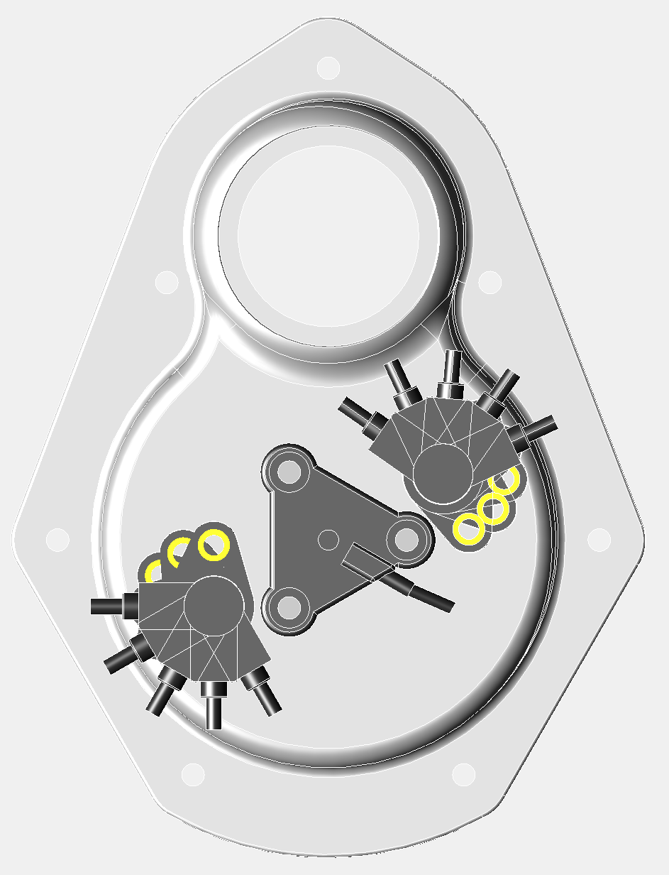
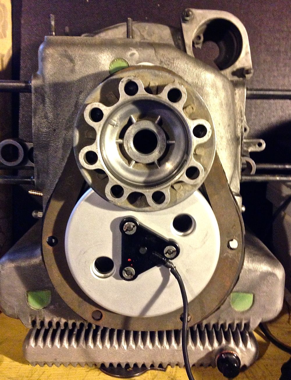
It was just a s well, because when I fitted the crankshaft pulley, I noticed the right hand sensor had very few options. The cable will foul the pulley, unless it is in the 1 or 2 o’clock positions, and it is best if it is tangental to the pulley, as this gives more room for dynamo V belt replacement. This is only really a consideration, as I am using sequential twin spark with the Imfsoft Ignition TCI module, and if I used a MicroSquirt, I could just use a single sensor and a toothed wheel. This will also be the case with electronic fuel injection too.
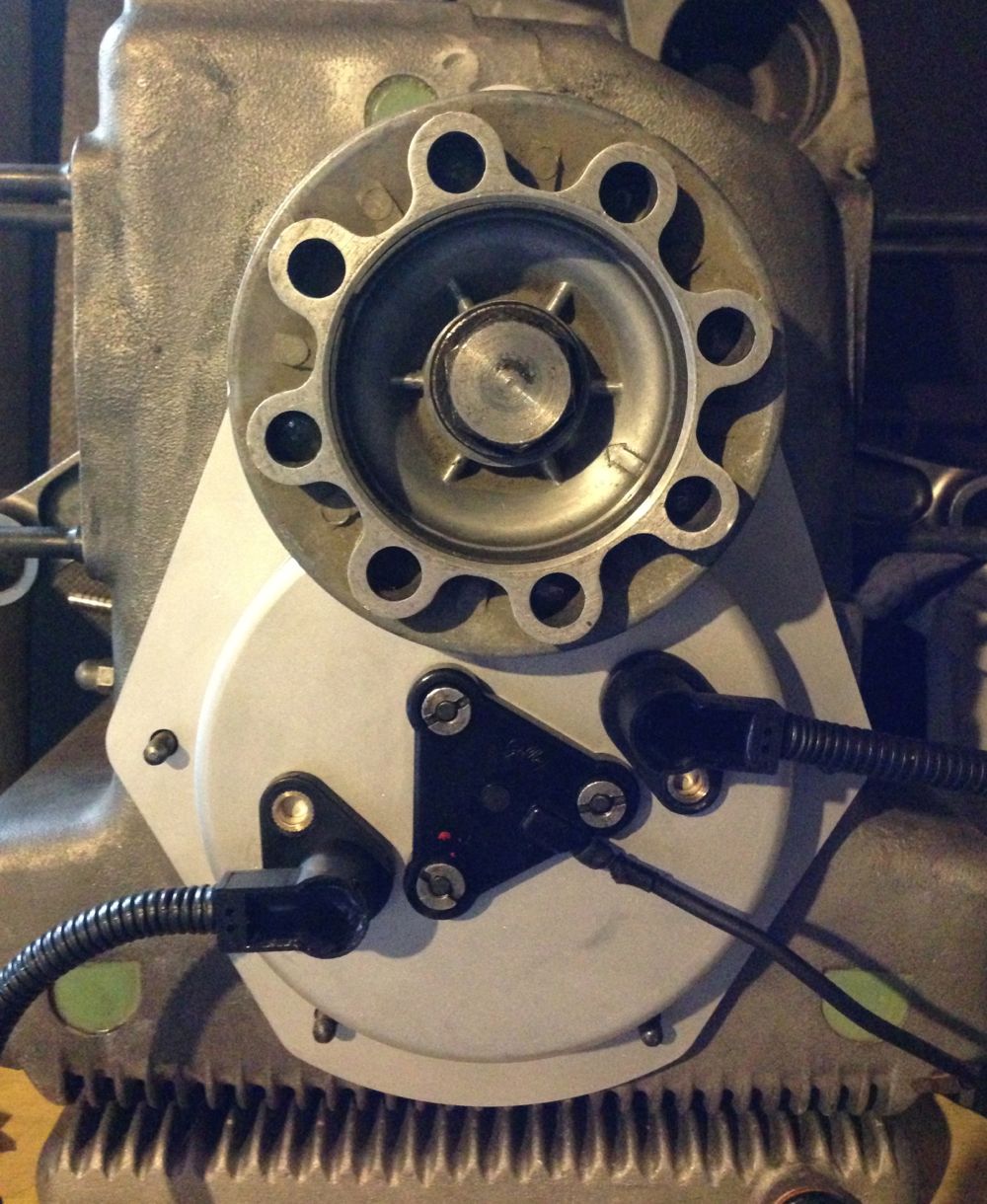
Notice how the Gelbey oil light sensor is rotated, which gives more clearance for sensor rotation.
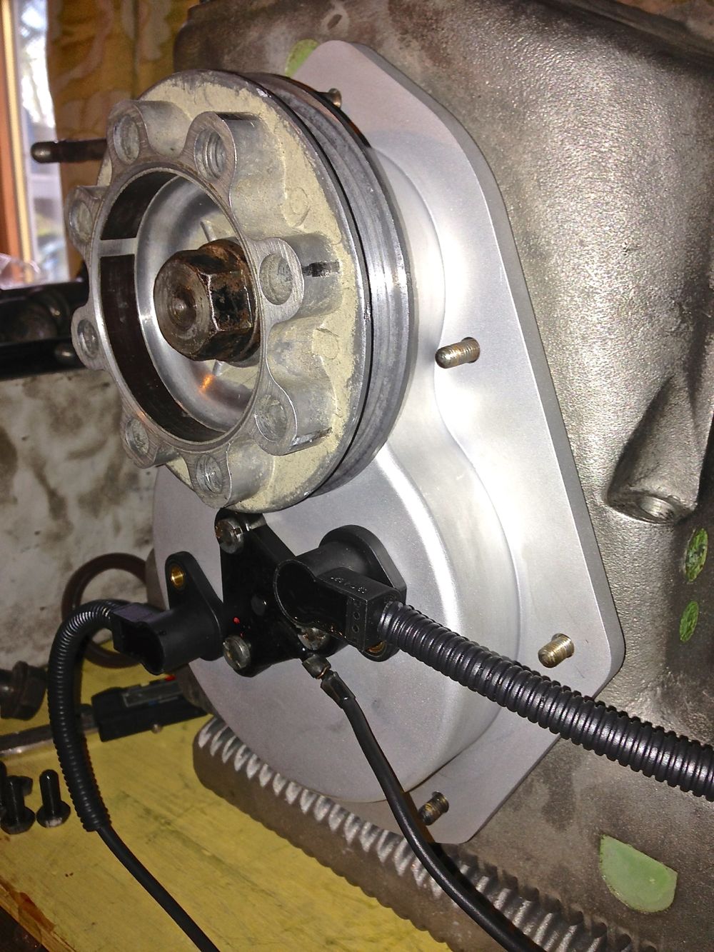
Tangental orientation below.
Next up was to check the cowling & fan fit
.
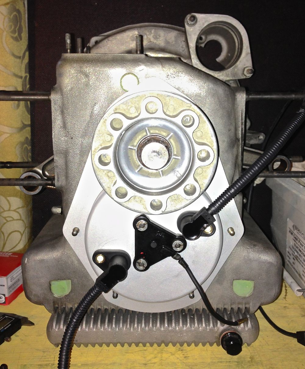
After this check the fan clearance, this is the front view, and how discreet is this cover. You wouldn’t realise it was there
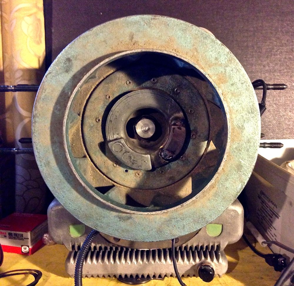
More importantly the clearance for the lower left hand sensor! Pretty tight, except the fan is pushed 5mm further forward if my measurements are right (phew)!
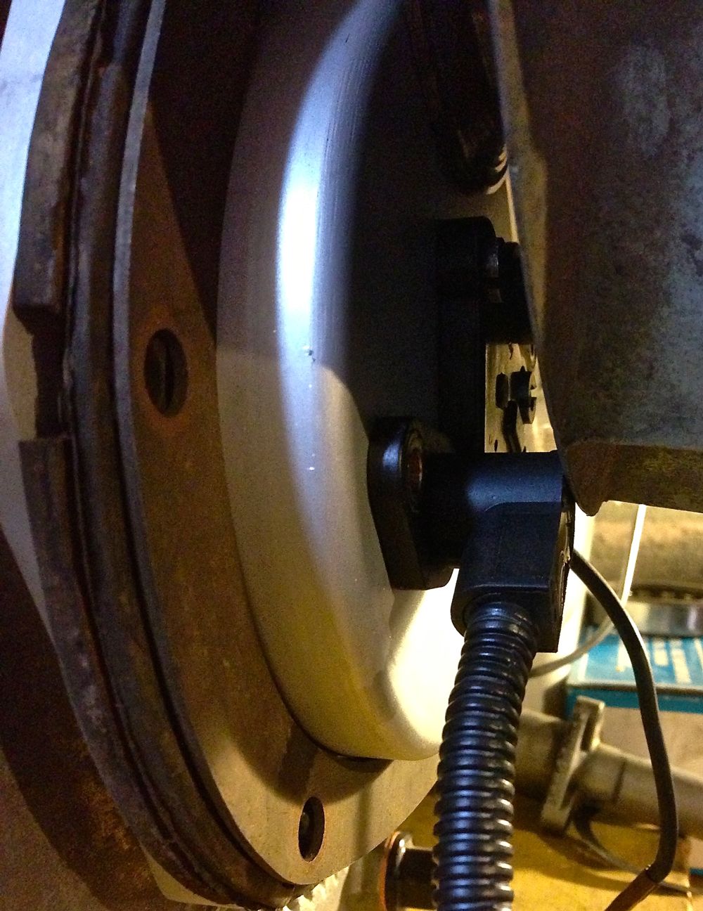
All in all, not a bad first stab, even if I do say so myself!
It was just a s well, because when I fitted the crankshaft pulley, I noticed the right hand sensor had very few options. The cable will foul the pulley, unless it is in the 1 or 2 o’clock positions, and it is best if it is tangental to the pulley, as this gives more room for dynamo V belt replacement. This is only really a consideration, as I am using sequential twin spark with the Imfsoft Ignition TCI module, and if I used a MicroSquirt, I could just use a single sensor and a toothed wheel. This will also be the case with electronic fuel injection too.
Notice how the Gelbey oil light sensor is rotated, which gives more clearance for sensor rotation.
Tangental orientation below.
Next up was to check the cowling & fan fit
.
After this check the fan clearance, this is the front view, and how discreet is this cover. You wouldn’t realise it was there
More importantly the clearance for the lower left hand sensor! Pretty tight, except the fan is pushed 5mm further forward if my measurements are right (phew)!
All in all, not a bad first stab, even if I do say so myself!
blog comments powered by Disqus
