New crankshaft design
22/04/16 01:21
I am finally updating the website after a long time out, and will be adding info and refining the content over the next few weeks, as I haven't been doing nothing Panhard before an enforced break.
DCNF carburettor modifications
22/04/16 01:20
Investigate the valve gear return spring tension
22/04/16 01:20
Crankshaft failure
08/02/16 01:21
A most disappointing start to the day, as I had a friend come round to the house, and he asked how the engine was going, so I said, "Have a look for yourself".
We nipped into the shed, and I started it, and he was gobsmacked it sound so quiet on open pipes, and after I released the choke, I left the engine on a slow idle to warm up. After a cup of tea, we went back to the shed, and I checked the exhausts and cylinders, and started to gently open the throttle. Then I dip three short blips on the throttle, "broom, broom, broom", and on the third blip just as I let the throttle go, there was an sudden "dink".
He looked at me, I looked at him, and just said, "It's seized, most odd". That was when the engine was almost ready to go in Brian's car, and all it needed were a few detailed tweaks, a clean with strip down and a rebuild.
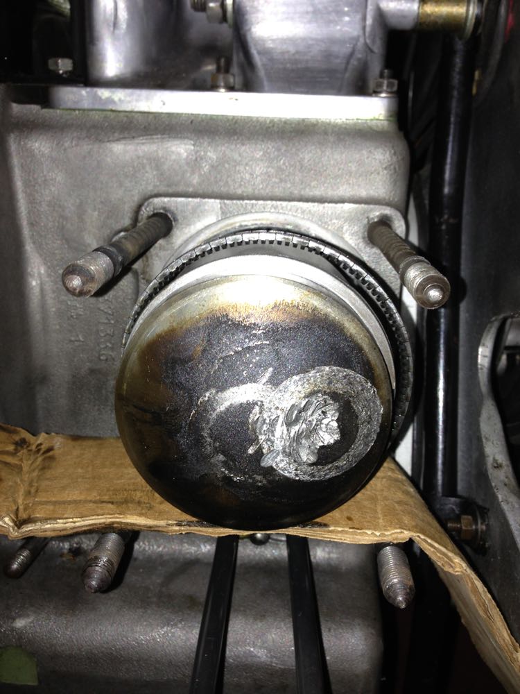
In a few hours the engine was stripped, the crankshaft split, and the cause inspected. It was a mystery, how could this crankshaft fail? It had only done 27 hours running, and how come the rod had friction welded itself to the crank web?
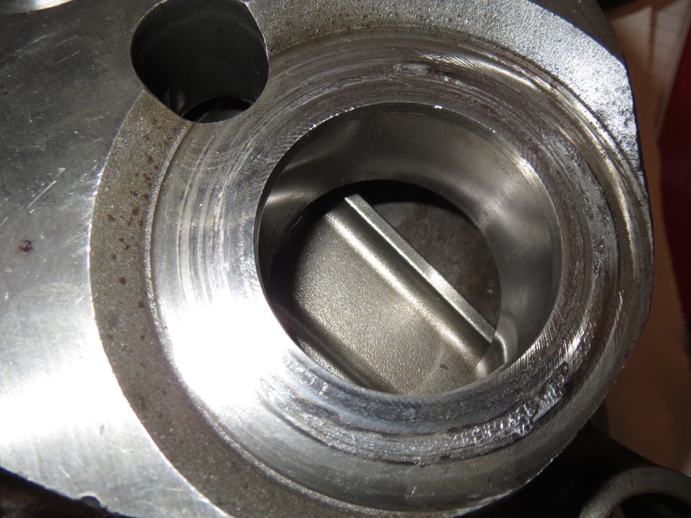
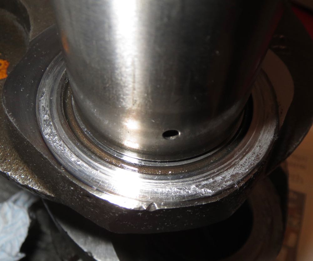
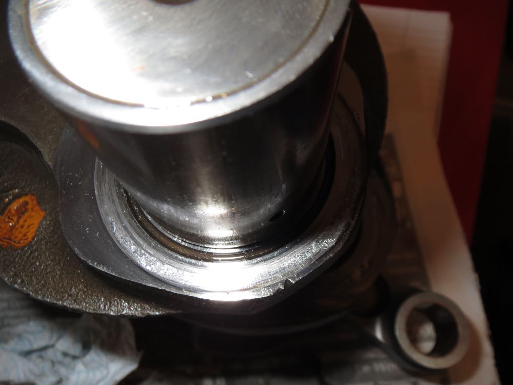
The pictures tell a story, as the rear rod has welded itself to the crankshaft webs, more so to the middle web than the rear, and there was plenty of oil, so what caused it?
It turns out the highest stresses are on the underside of the crankpins closest to the connecting rods, and the residual stresses in the interference are additive, such that the metal yields, and causes the crankshaft to flex. At low to mid speeds these are highest from the compressive forces of combustion, and later as the revs increase the inertial loads are greater and more destructive.
On inspection and relating to other roller bearing engines, the crankshaft to connecting rod side clearances are very low, at around 0.1mm, whereas most motorcycles run at around 0.4-0.7mm. As you open the clearances up, you need more oil flow to compensate for the losses, but that's no bad thing, as it can benefit other areas of the engine, and Brian's engine had a lot of oil on the underside of both pistons, and there was no discolouration under the crown either. In fact they had a rich golden syrup like colour, which is a very good sign indeed.
So the flexing of the crankshaft was due to the "blipping" of the throttle and the harmonics it introduced, and these combined fatally and killed the crankshaft, but it doesn't happen to a standard crankshaft, so what's different.
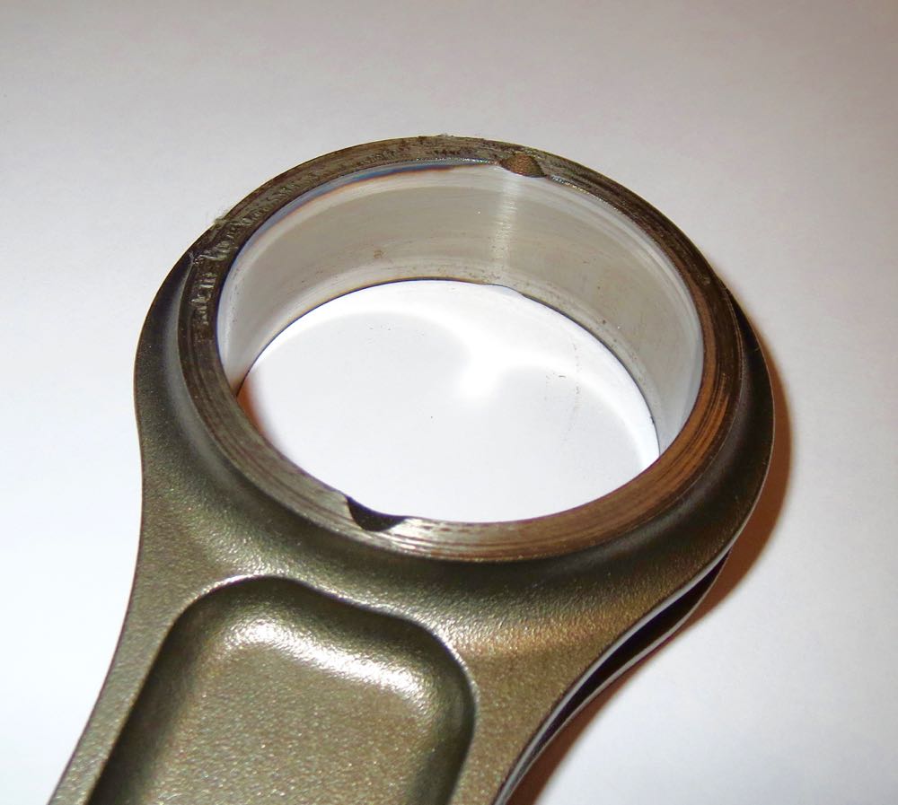
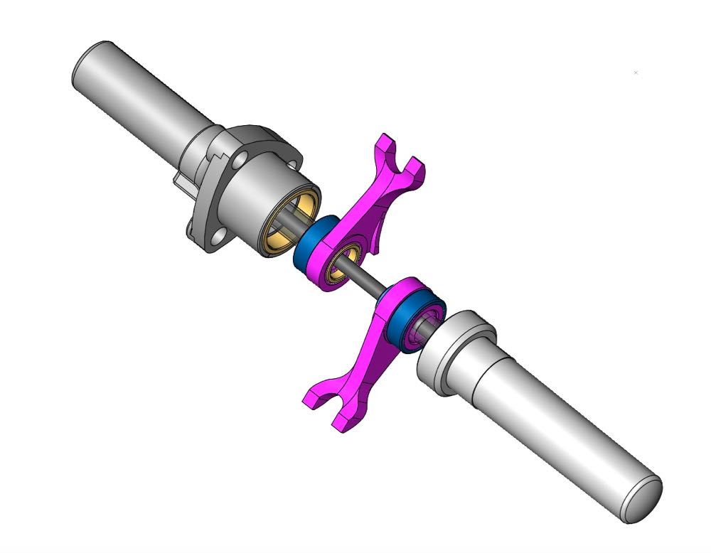
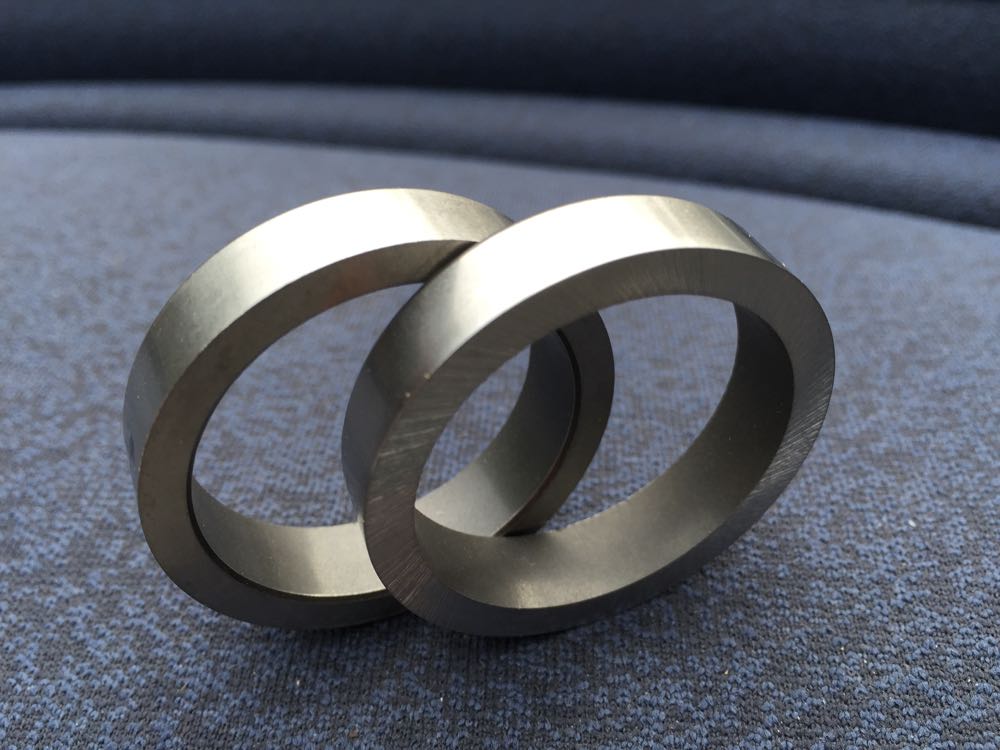
Well, the clue is here in this picture, a sleeved crankpin.
It turns out the bending moment of a round bar is proportional to the diameter to the power of 4, or D^4, which means if a 40mm bar has a bending moment of 100%, a 35mm bar has 59% of this value.
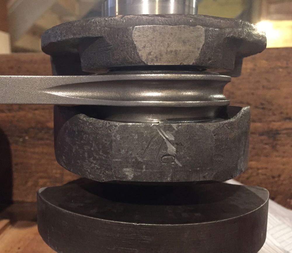
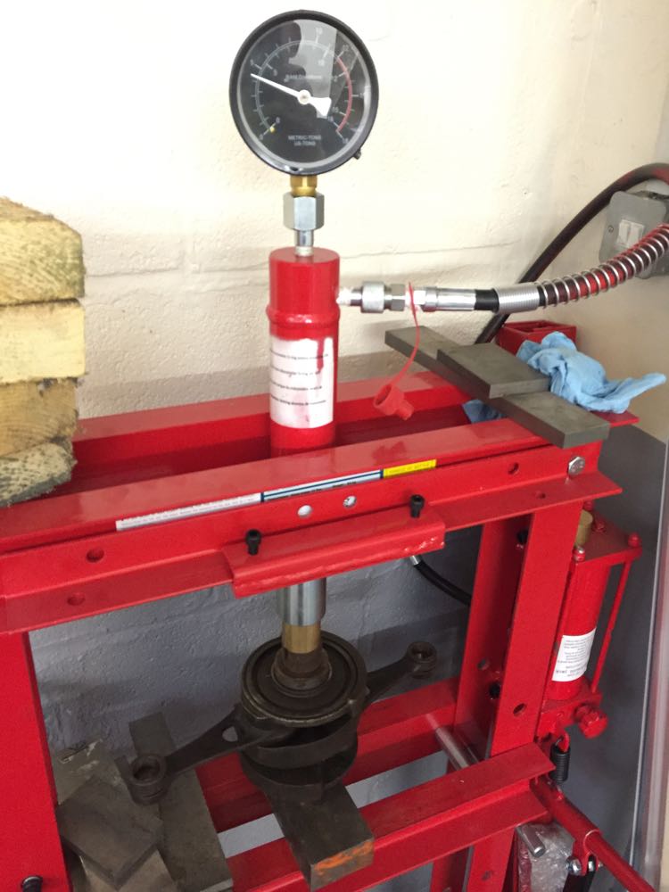
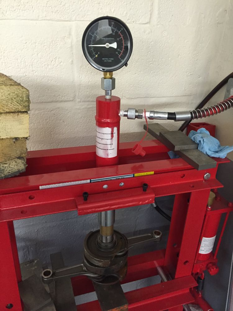
This is a huge reduction, and why you don't want to go do a sleeved route. This was also seen in a load deflection test, that I carried out. I wanted to understand whether I could test this, so I put a old crankshaft and the reassembled damaged one, and by applying a pressure to the ends it would cause the crankshaft to flex, without brinnelling the rollers into the crank pin, and the load limit was the rotation of the connecting roads. When it was too hard to rotate the rods, as in they had locked up by the crank webs touching them, then it was time to record the pressure.
As you can see the original crankshaft assembly took 5 tonnes of pressure, and Brian's 3 tonnes or so, which is about 60% of the original, and correlates well with the physical properties.
We nipped into the shed, and I started it, and he was gobsmacked it sound so quiet on open pipes, and after I released the choke, I left the engine on a slow idle to warm up. After a cup of tea, we went back to the shed, and I checked the exhausts and cylinders, and started to gently open the throttle. Then I dip three short blips on the throttle, "broom, broom, broom", and on the third blip just as I let the throttle go, there was an sudden "dink".
He looked at me, I looked at him, and just said, "It's seized, most odd". That was when the engine was almost ready to go in Brian's car, and all it needed were a few detailed tweaks, a clean with strip down and a rebuild.
In a few hours the engine was stripped, the crankshaft split, and the cause inspected. It was a mystery, how could this crankshaft fail? It had only done 27 hours running, and how come the rod had friction welded itself to the crank web?
The pictures tell a story, as the rear rod has welded itself to the crankshaft webs, more so to the middle web than the rear, and there was plenty of oil, so what caused it?
It turns out the highest stresses are on the underside of the crankpins closest to the connecting rods, and the residual stresses in the interference are additive, such that the metal yields, and causes the crankshaft to flex. At low to mid speeds these are highest from the compressive forces of combustion, and later as the revs increase the inertial loads are greater and more destructive.
On inspection and relating to other roller bearing engines, the crankshaft to connecting rod side clearances are very low, at around 0.1mm, whereas most motorcycles run at around 0.4-0.7mm. As you open the clearances up, you need more oil flow to compensate for the losses, but that's no bad thing, as it can benefit other areas of the engine, and Brian's engine had a lot of oil on the underside of both pistons, and there was no discolouration under the crown either. In fact they had a rich golden syrup like colour, which is a very good sign indeed.
So the flexing of the crankshaft was due to the "blipping" of the throttle and the harmonics it introduced, and these combined fatally and killed the crankshaft, but it doesn't happen to a standard crankshaft, so what's different.
Well, the clue is here in this picture, a sleeved crankpin.
It turns out the bending moment of a round bar is proportional to the diameter to the power of 4, or D^4, which means if a 40mm bar has a bending moment of 100%, a 35mm bar has 59% of this value.
This is a huge reduction, and why you don't want to go do a sleeved route. This was also seen in a load deflection test, that I carried out. I wanted to understand whether I could test this, so I put a old crankshaft and the reassembled damaged one, and by applying a pressure to the ends it would cause the crankshaft to flex, without brinnelling the rollers into the crank pin, and the load limit was the rotation of the connecting roads. When it was too hard to rotate the rods, as in they had locked up by the crank webs touching them, then it was time to record the pressure.
As you can see the original crankshaft assembly took 5 tonnes of pressure, and Brian's 3 tonnes or so, which is about 60% of the original, and correlates well with the physical properties.
Bench testing the engine
28/09/15 01:20
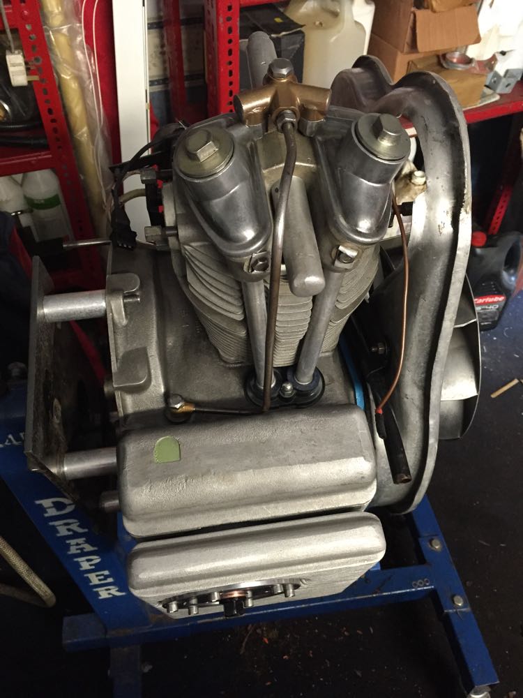
It is now late September in 2015, and Brian's engine is finally getting it first run in after the exhaust valve failure in mid 2013.
What a journey it has been to get this far, and there is a short video clip of it running on the original and carburettor pre failure on the stand, with no exhausts fitted.
Yes, it's idling a little fast, but everything is going round! :)
First start
This is a temporary oil light feed to check everything is working OK. Engine cranking introduces a flicker, but once the revs pick up, the oil light goes out at idle very comfortably, and this is with a standard, but enhanced pump, new oil light piston, plus revised crankshaft lubrication, and it's a measure of how improved the circuit is.
Oil Light Test
I had to add some downpipes to avoid getting fumes blowing into the work area, and also take the noise down bit, whilst I looked at other stuff. The first phase was to run the engine up standard, then convert the ignition over to the programmable system, and then establish a default curve that mimicked the original ignition. Later modify this, and tune the MAP sensor settings to enhance the pick up and drivability off idle. Later still double check the rev limiter is functioning, and using the built in diagnostics that all the sensors and toothed wheel settings are not causing any glitches.
This first thing I noticed was the idle was slightly erratic, and would settle at different rpms when opening the throttle slightly. It turned out the spindle wears directly in the zinc body, and unlike Weber carburettors they do not run in bearings, and have any seals either. Here is a short clip, showing the revs fluctuation as you apply pressure top the spindle.
Throttle Spindle Play
Cylinder finished
12/09/15 13:15
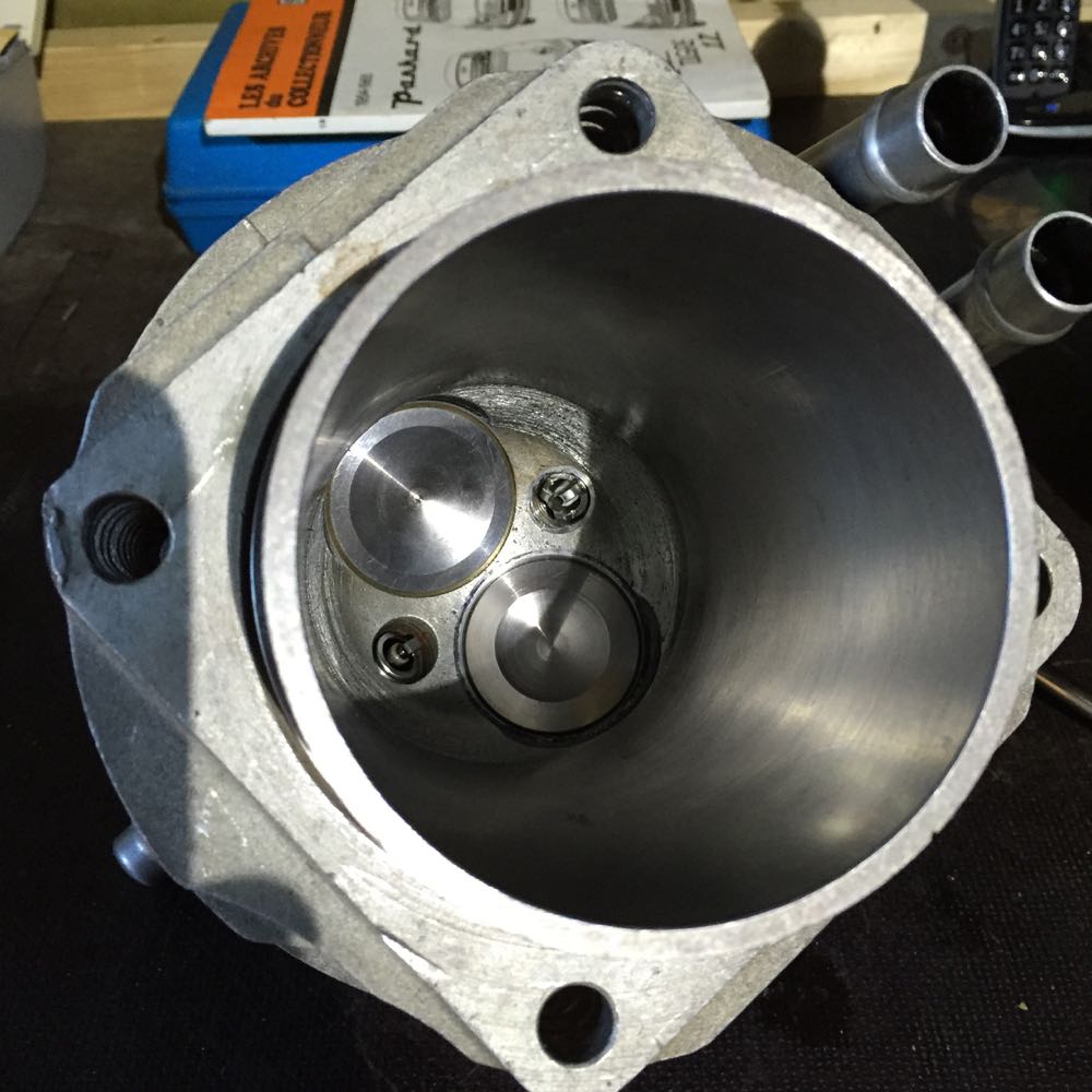
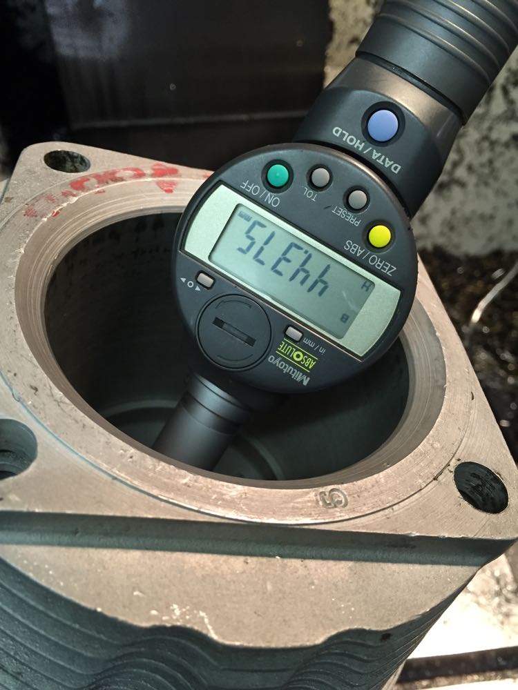
Pressure testing the cylinder using an airline, a drain stopper, and a collection of fittings to check valve was seating OK.
After all those seat cutting woes, I finally got the cylinder finished.
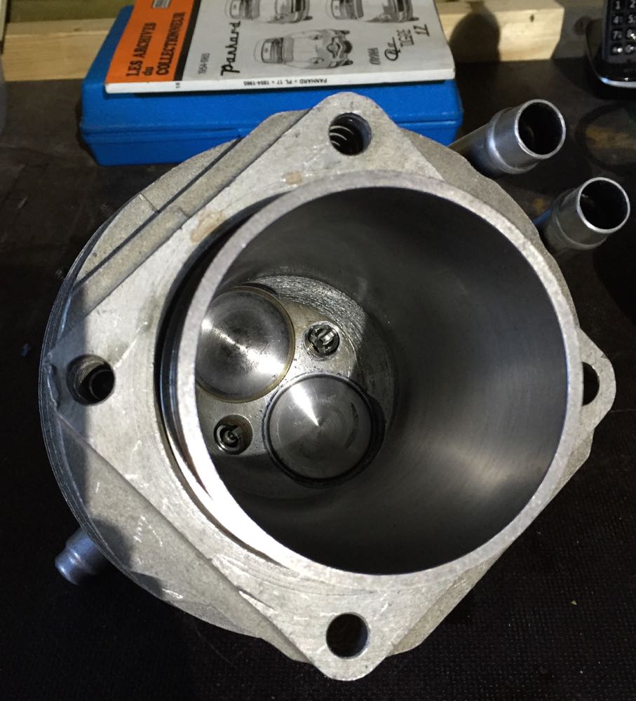
As the seats were finished, I thought, I'd try my new inlet and exhaust valves in here for fit, and they look OK, with respect to the seats. The important thing is these valves are lighter, have similar weights for the inlet & exhaust, and currently being tested in a Panhard racer in Europe. I don't expect any problems as they are 21/4N material, and used in racing engines around the world.
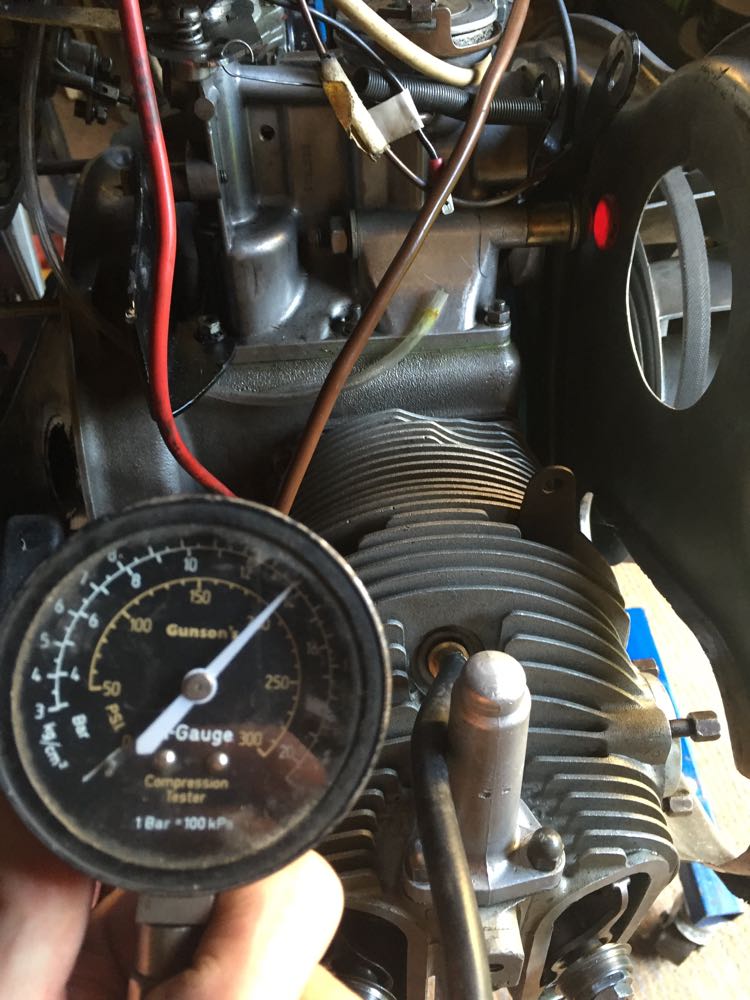
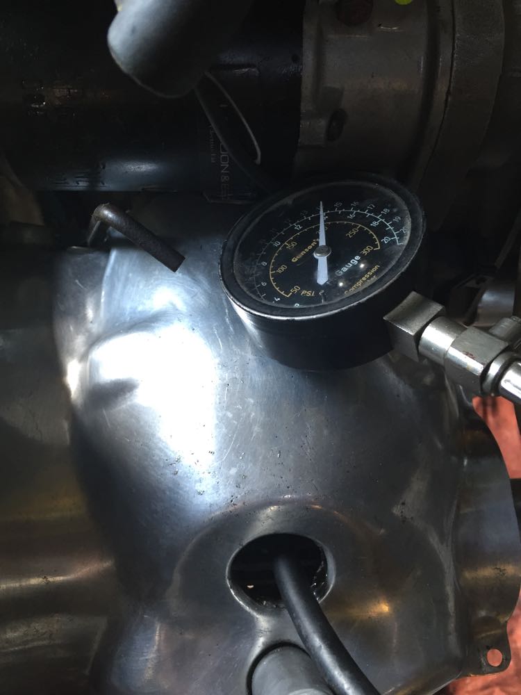
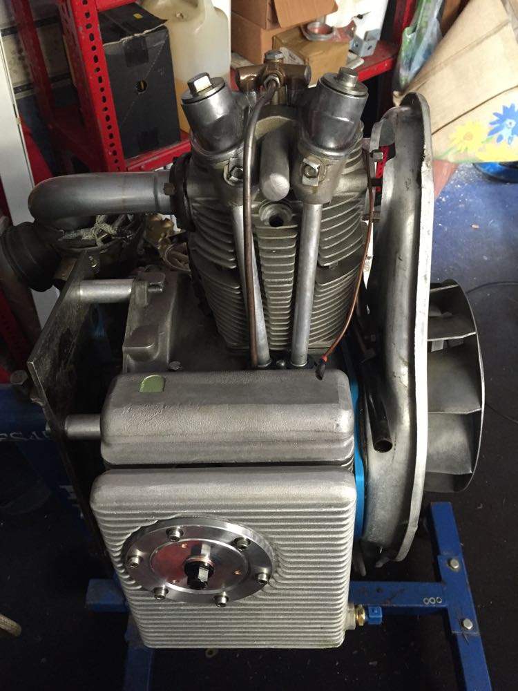
A few weeks later the cylinders are fitted, and the compression is a very healthy 14 bar or 200 psi on both cylinders. Unheard of and incredulous pressures for a Panhard engine doing about 5 turns on the starter, but there was a sting in the tale, after I got it running.
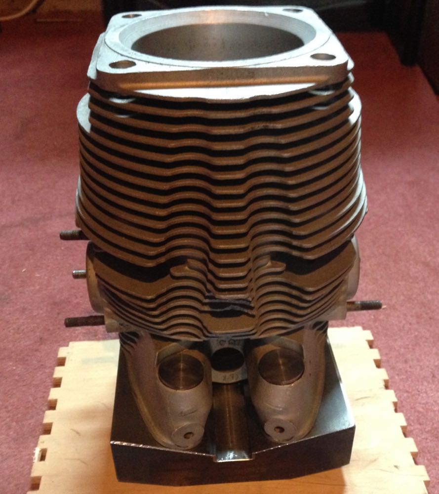
This is the finished cylinder, showing the sump extension and DIY aluminium sump plate.
Twin plugged cylinders, which will be used to evaluate different ignition advance curves further down the line.
Programmable ignition using multi toothed wheel
22/07/15 01:20
For Brian's 2012 engine, I used a twin sensor front timing cover, because that's what the lower cost Imfsoft Direct Ignition needed to create a sequential, non wasted spark on a two cylinder engine. It was decided to go this route, as this makes the best use of the camshaft timing and long inlet pipes, as anecdotal evidence suggested that wasted spark Panhard had a less favourable torque curve. The other requirement was to drive four coils, as the cylinders were twin plugged.
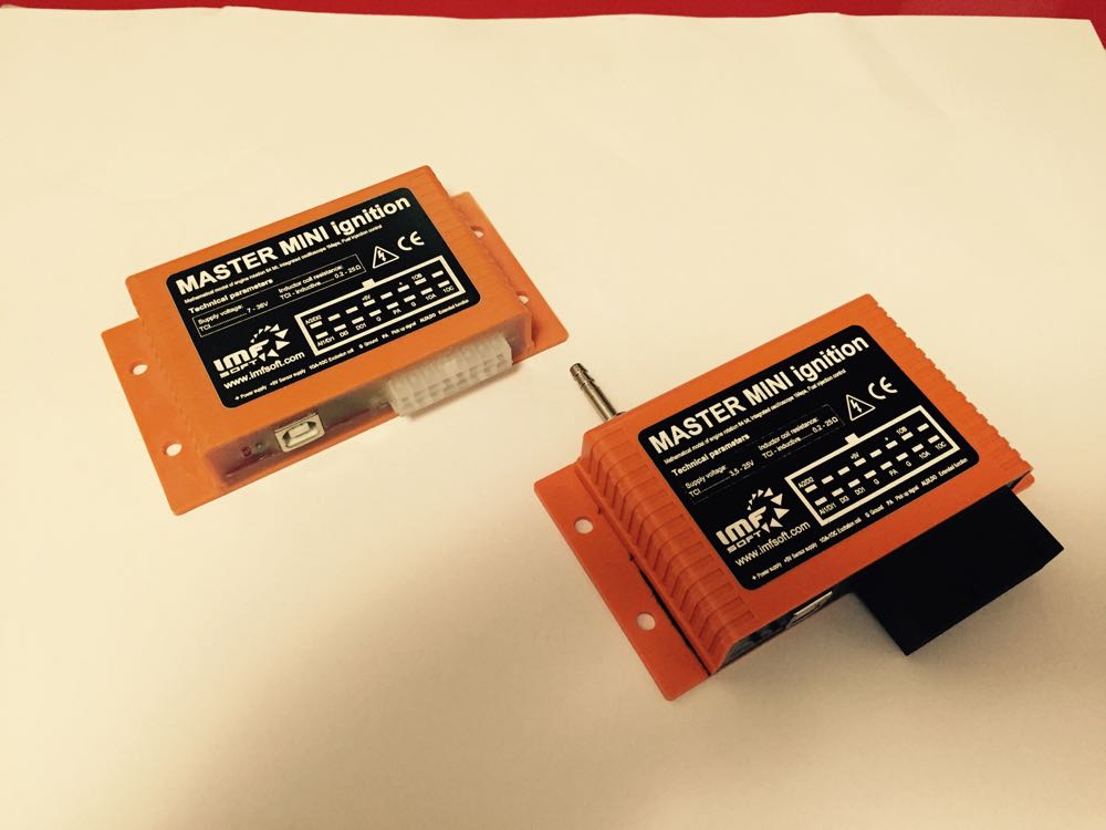
During 2014/2015 Imfsoft superseded the old ignition unit with another that allowed for a multi-toothed wheel, and it had enhanced flexibility, including an extra channel, so you could switch on a fuel pump relay, or even use mono-point injection., and the one on the right above, has a built in 1.5 bar MAP sensor, which gives more flexibility too. This meant a revision to the timing cover strategy, and I decided to just make one type, that is with a one hole sensor, and for people that didn't want the ignition option, just a front seal upgrade, I had a cover plug, that fitted inside the sensor recess.
Brian's engine was going to get the missing tooth upgrade, and the new cover. This was an actual production item being tested here.
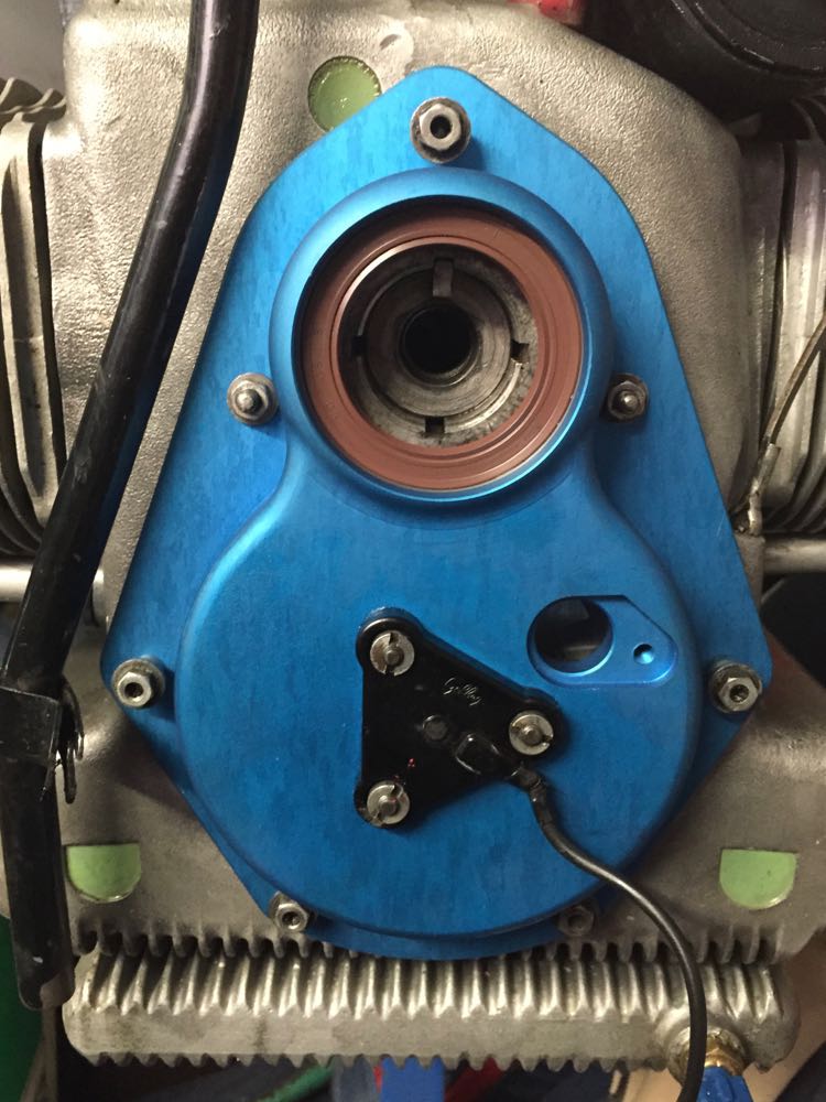
At the same time I needed to fit and test the new pulley I had made, so it was tested on Brian's engine too.
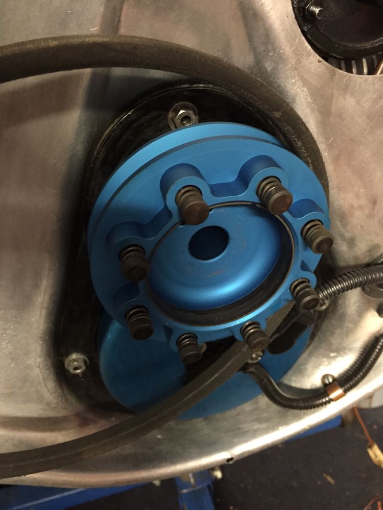
Before this was fitted I tested some different trigger wheels too, so that I could draw them up & get them laser cut later.
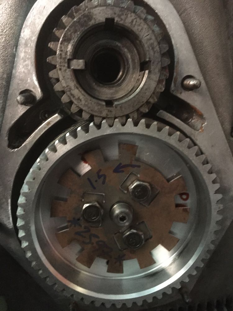
It turned out that this wheel was going to cause me problems, yet it ran to over 20,000 rpm on the test rig, no issues with a MicroSquirt and the same sensor.
One of the nice things about the new Imfsoft software, was the tooth trigger analysis functions were better, and by looking at the "oscilloscope" traces, you could see what the ignition module was seeing, and processing the information, and this saved y bacon a few times.
What I didn't know was the firmware was corrupted in my Imfsoft, and it took a future firmware upgrade at a later date to cure this, but once it was done the unit has been rock solid ever since. They do represent tremendous "bangs for bucks" compared to other systems, and are very sophisticated electronically.
During 2014/2015 Imfsoft superseded the old ignition unit with another that allowed for a multi-toothed wheel, and it had enhanced flexibility, including an extra channel, so you could switch on a fuel pump relay, or even use mono-point injection., and the one on the right above, has a built in 1.5 bar MAP sensor, which gives more flexibility too. This meant a revision to the timing cover strategy, and I decided to just make one type, that is with a one hole sensor, and for people that didn't want the ignition option, just a front seal upgrade, I had a cover plug, that fitted inside the sensor recess.
Brian's engine was going to get the missing tooth upgrade, and the new cover. This was an actual production item being tested here.
At the same time I needed to fit and test the new pulley I had made, so it was tested on Brian's engine too.
Before this was fitted I tested some different trigger wheels too, so that I could draw them up & get them laser cut later.
It turned out that this wheel was going to cause me problems, yet it ran to over 20,000 rpm on the test rig, no issues with a MicroSquirt and the same sensor.
One of the nice things about the new Imfsoft software, was the tooth trigger analysis functions were better, and by looking at the "oscilloscope" traces, you could see what the ignition module was seeing, and processing the information, and this saved y bacon a few times.
What I didn't know was the firmware was corrupted in my Imfsoft, and it took a future firmware upgrade at a later date to cure this, but once it was done the unit has been rock solid ever since. They do represent tremendous "bangs for bucks" compared to other systems, and are very sophisticated electronically.
Investigate piston to valve clearance
09/05/15 01:20
The valve failing in 2013 was a big surprise, as I had enough valve clearance in theory, but the reality was that there was lost motion in the valve gear, and at higher revs, insufficient spring tension to control the valve gear. The exhaust valves on the Panhard are 12% heavier than the inlets, and acceleration is directly proportional to mass, this was sufficient enough to overcome the spring tension, and have excessive travel.
Once contact was made, it was a second before the destruction ripped through the combustion chamber. I initially thought it was the two piece valve that had let go, but the piston doesn't lie, and more importantly the same symptoms, with reduced impact was seen on the other cylinder. This explains why I couldn't run the engine up, and had no compression on both.
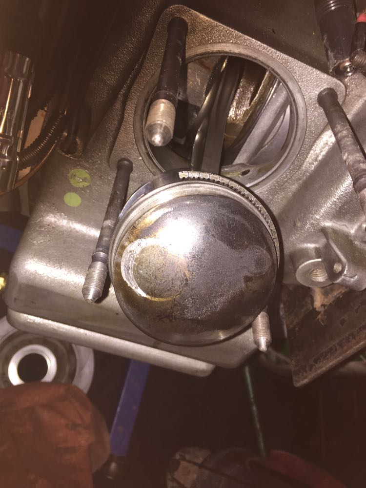
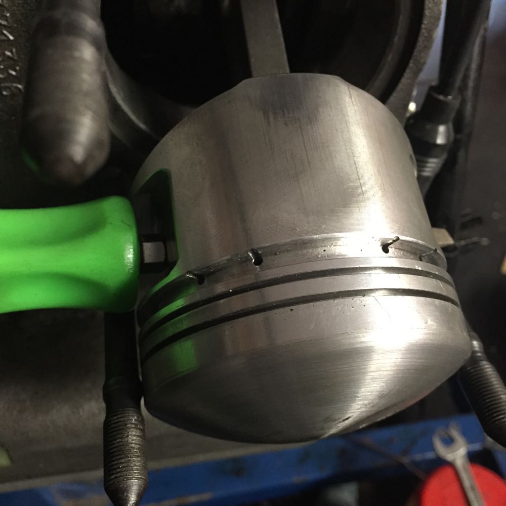
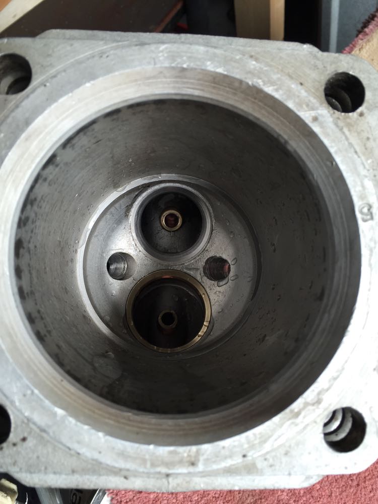
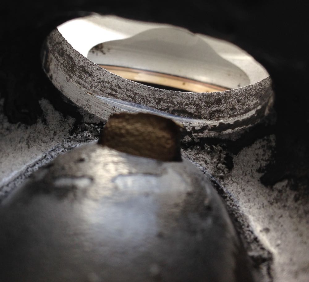
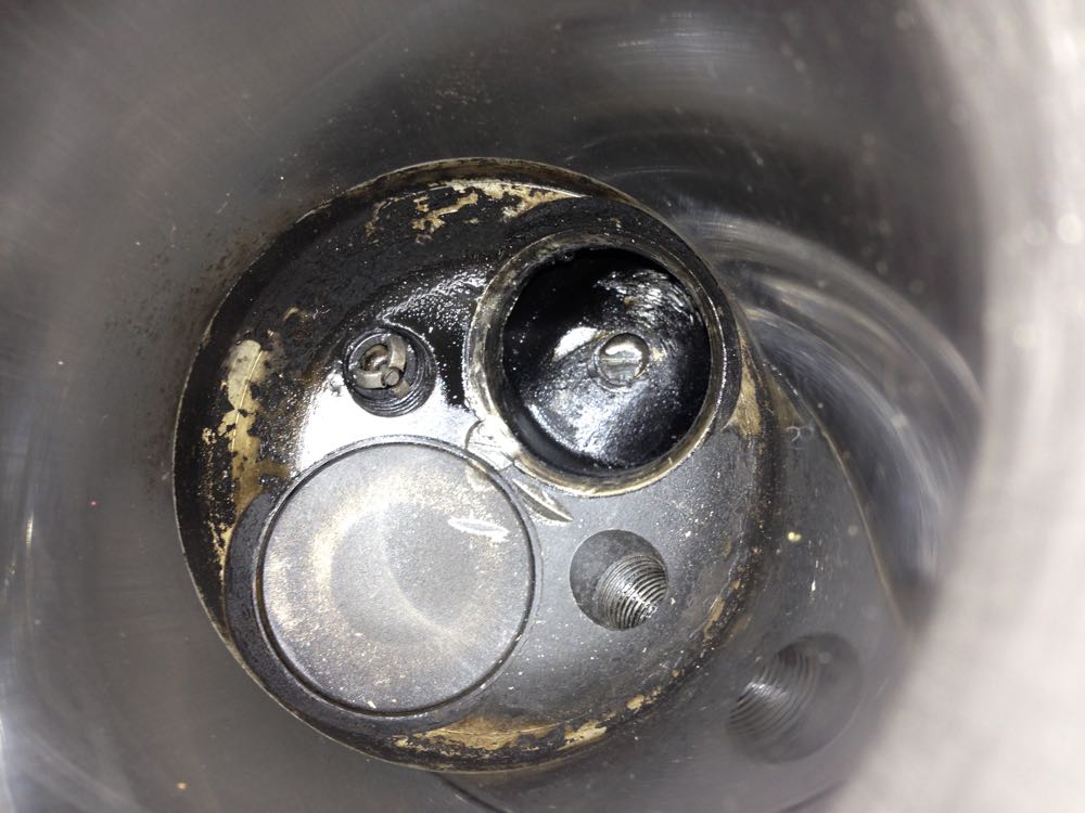
This was the state of the valve clearances when inspecting the dropped valve head cylinder, showing the markings to the piston, and interestingly you can see the effect of the higher pistons. The outer circumference of the piston is just catching the combustion chamber here, so it looks like the piston will have to be tweaked, otherwise the rocking action will possibly cause serious contact. This isn't getting rebuilt at this phase, I am doing a set up test with the failed components to find what the settings were when it broke. Later you use this information to tweak, and correct running issues.
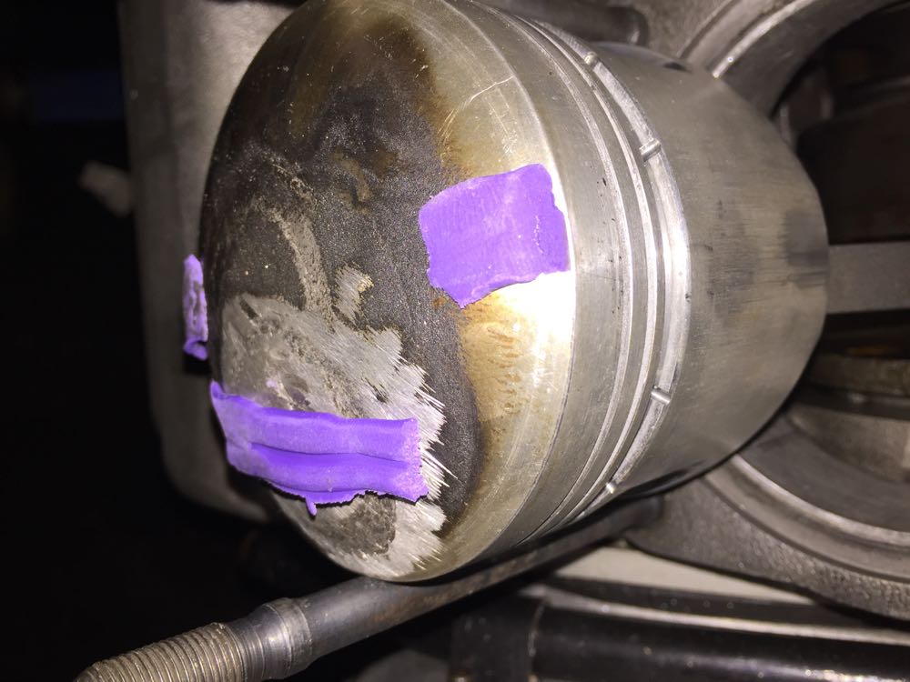
Here's the same piston with plenty of valve clearance in its final position and a modified circumference to prevent contact.
Now for the other side, and I did this because I had only stripped down the affected cylinder by now, and I thought the compression was variable, and the valve was ever so slightly bent, by piston to valve contact yet again, but not quite as much as the other side. Again it was the heavier exhaust valve, and this discovery led to a different route when I was making some replacement valves, but that's for another part of the website, but the CAD was busted out again for this too.
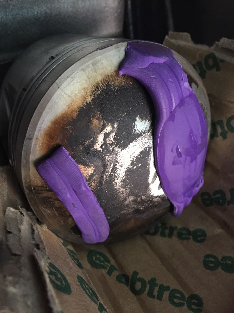
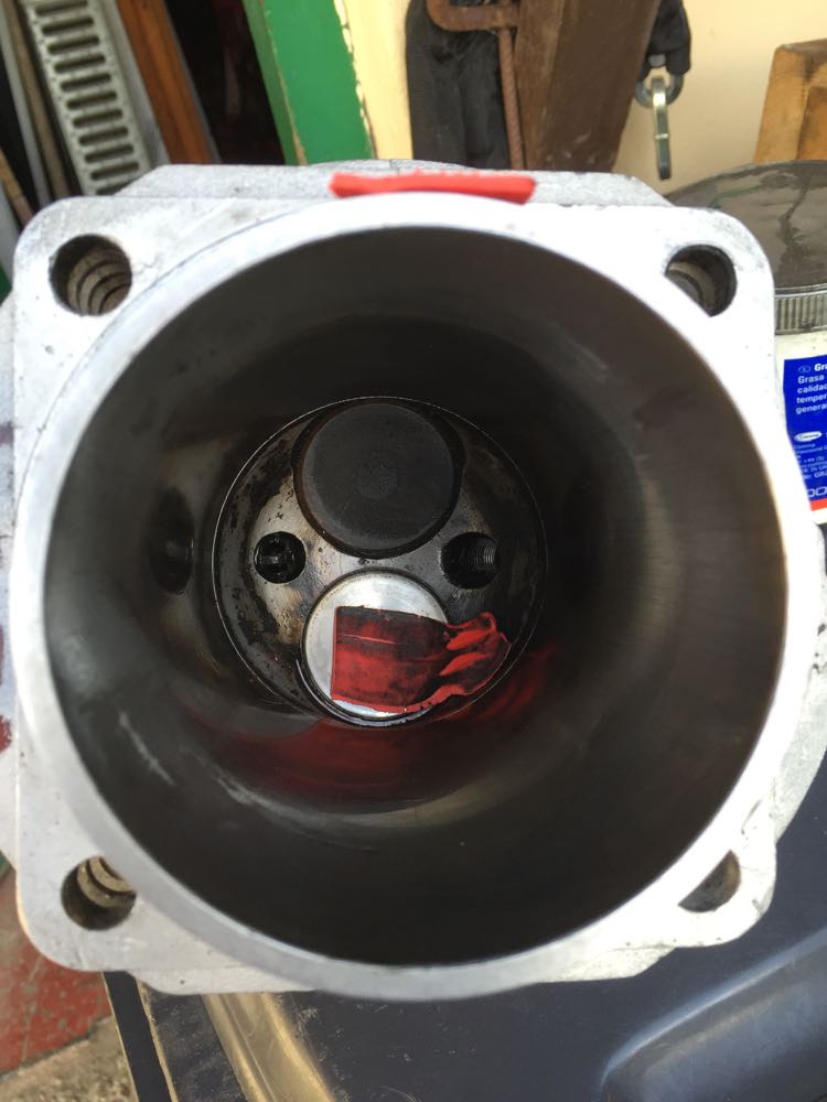
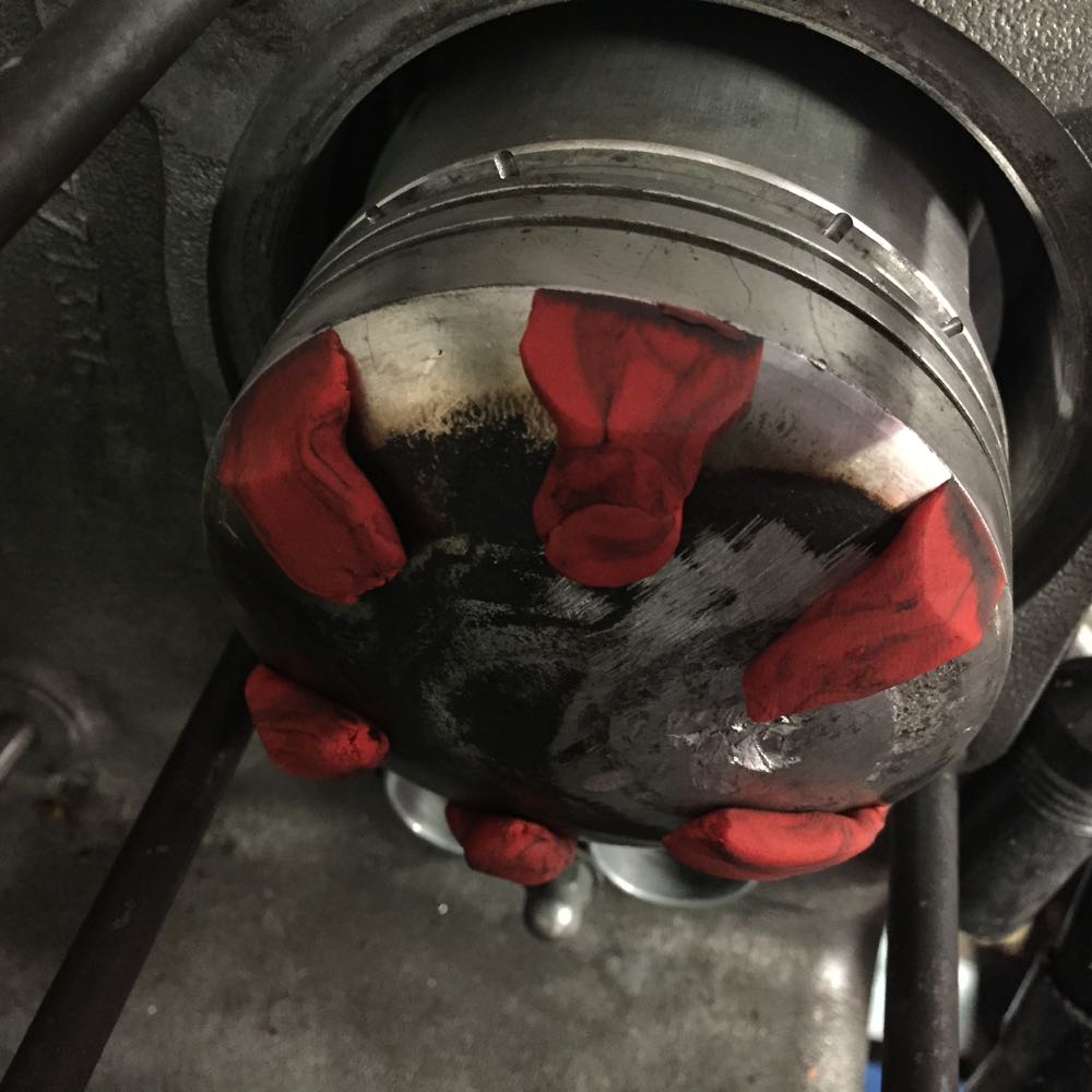
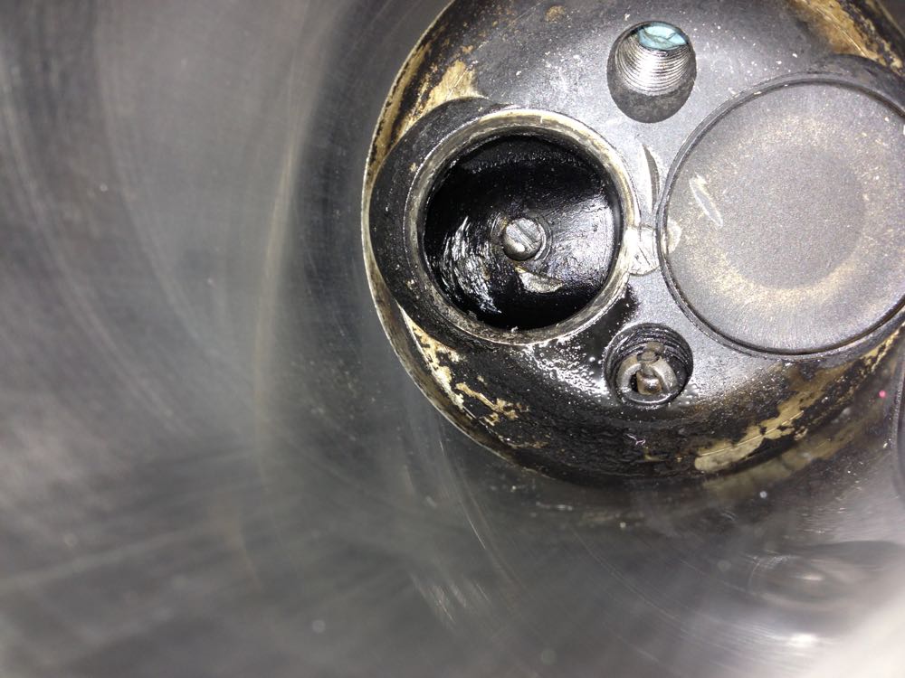
Back to the other cylinder, and the oily mess is from trying to restart the engine after failure by the roadside, as well as some of the running conditions.
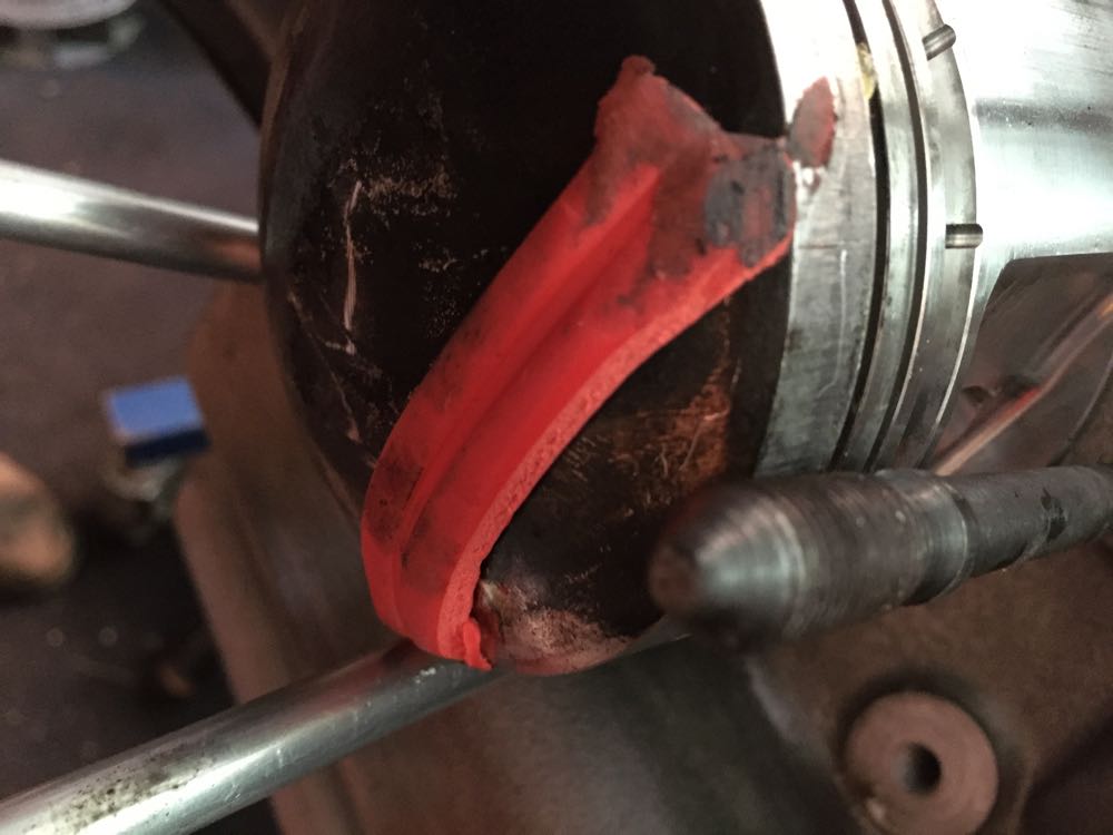
The Plasticene shows the same closeness at the edge of the piston, so this was modded too.
New exhaust valve, plenty of clearance now.
By the middle of July 2015, the pistons had been machined, and everything double checked. they still needed cleaning, but at least the pressures were good and clearances optimised.
Once contact was made, it was a second before the destruction ripped through the combustion chamber. I initially thought it was the two piece valve that had let go, but the piston doesn't lie, and more importantly the same symptoms, with reduced impact was seen on the other cylinder. This explains why I couldn't run the engine up, and had no compression on both.
This was the state of the valve clearances when inspecting the dropped valve head cylinder, showing the markings to the piston, and interestingly you can see the effect of the higher pistons. The outer circumference of the piston is just catching the combustion chamber here, so it looks like the piston will have to be tweaked, otherwise the rocking action will possibly cause serious contact. This isn't getting rebuilt at this phase, I am doing a set up test with the failed components to find what the settings were when it broke. Later you use this information to tweak, and correct running issues.
Here's the same piston with plenty of valve clearance in its final position and a modified circumference to prevent contact.
Now for the other side, and I did this because I had only stripped down the affected cylinder by now, and I thought the compression was variable, and the valve was ever so slightly bent, by piston to valve contact yet again, but not quite as much as the other side. Again it was the heavier exhaust valve, and this discovery led to a different route when I was making some replacement valves, but that's for another part of the website, but the CAD was busted out again for this too.
Back to the other cylinder, and the oily mess is from trying to restart the engine after failure by the roadside, as well as some of the running conditions.
The Plasticene shows the same closeness at the edge of the piston, so this was modded too.
New exhaust valve, plenty of clearance now.
By the middle of July 2015, the pistons had been machined, and everything double checked. they still needed cleaning, but at least the pressures were good and clearances optimised.
Seat cutting woes
03/05/15 00:50
Making yet another cylinder
27/04/15 00:30
So lets start again! :(
Then it was off to the CNC shop and get it machined using the same jig & fixture.
A day later, the seat was cold enough and the cylinder was heated, and the seat & guide dropped in place. In the picture below, you can see the heat from the cylinder blueing up the seat as the heat soaks back.
Then it was off to the CNC shop and get it machined using the same jig & fixture.
A day later, the seat was cold enough and the cylinder was heated, and the seat & guide dropped in place. In the picture below, you can see the heat from the cylinder blueing up the seat as the heat soaks back.
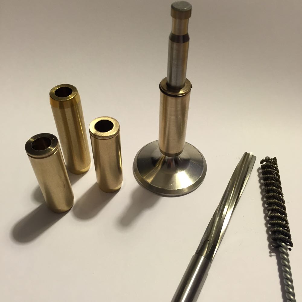
Making new valve guides
16/01/15 00:07
Now that the cylinder had been machined, it was time to start rebuilding it, so I purchased some oversized bronze valve guides and looked at machining them to suit. The outer diameter was sized to the reamed hole in the cylinder, and I had increased the diameter to 14mm nominal to create a good mating surface and better interference fit.
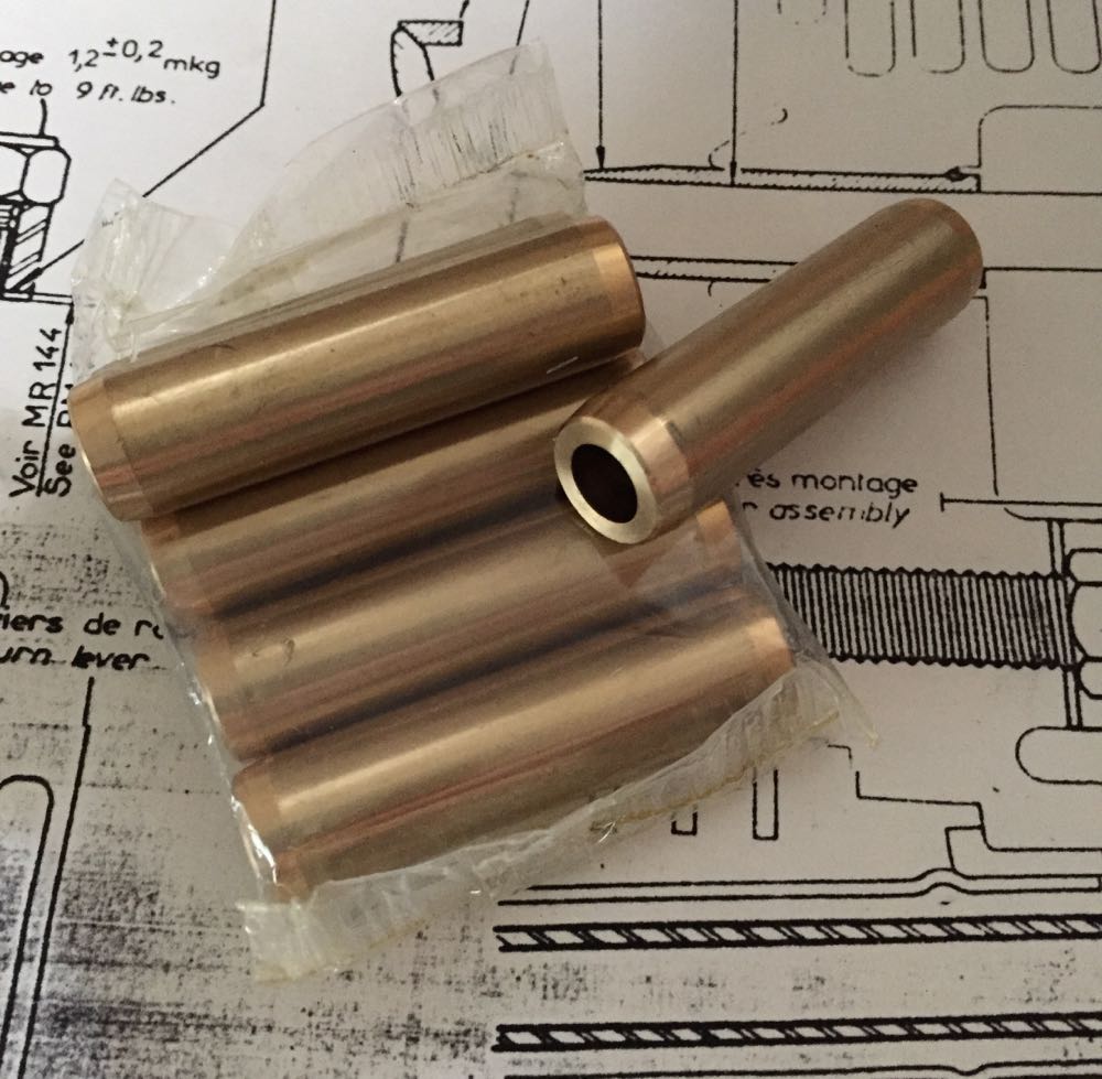
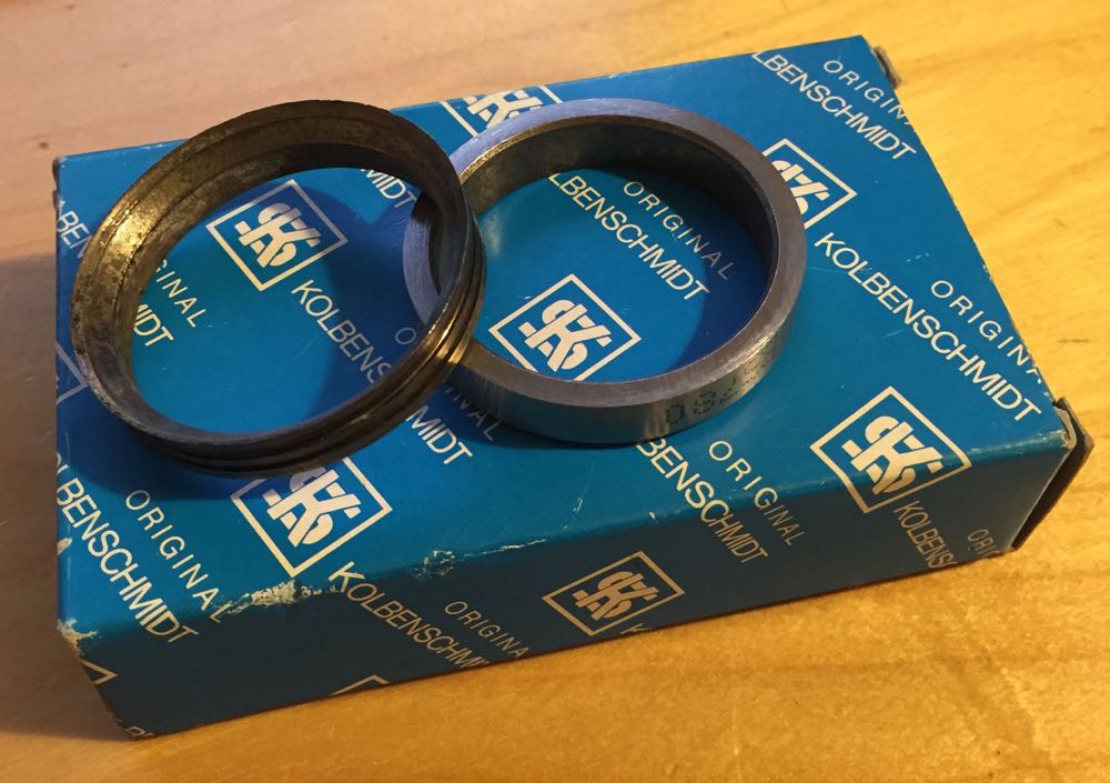
These were going to be shortened & grooved for the wire ring later, and it was a lot later, because in Feb 2015 the larger diameter valve seats arrived.
It was now March 2015, and the valves, guides and seats I was going to use were all made, as well as having a reamer ground to size, and a new FlexHone purchased, as I was using an 8.5mm Alain Lauffenburger exhaust valve. It had a similar weight to the other cylinder, but that's for another day.
New guide and seat installed, partially machined, and it's now late April 2015.
By this point there was an issue with the valve seat cutting and I had no idea what was going wrong, so I "scrapped" the cylinder, as I wasn't happy with it and had to start again.
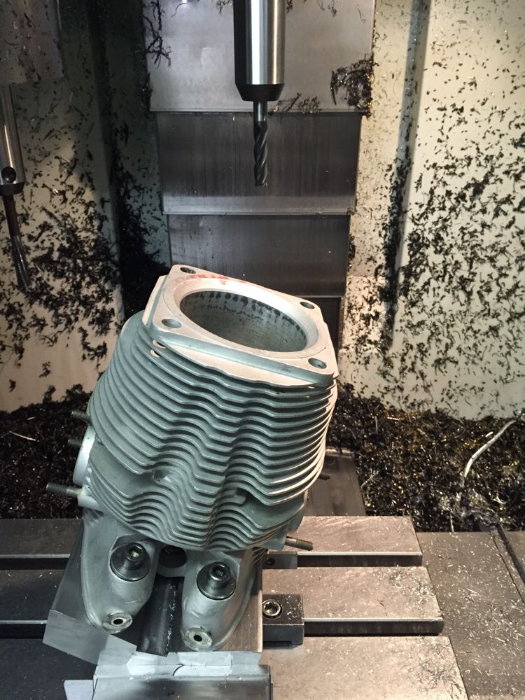
Repairing the damaged cylinder
22/08/13 00:50
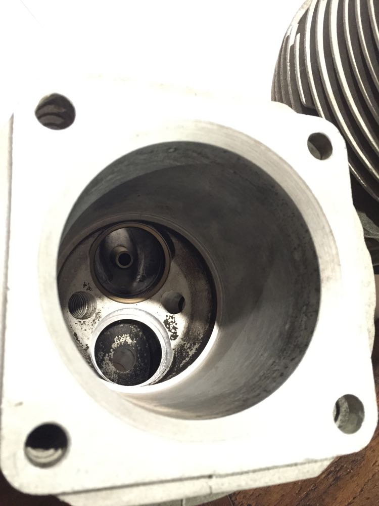
This is a close up of the damage to the cylinder, and you can see the broken valve head has caused some nasty impacts, so I decided to scrap the cylinder.
As these are all in one cylinders and heads, as in very deep, it's a mess trying to get down to weld and machine afterwards, and I thought it wasn't worth the effort. I found another cylinder that was a similar size with the liner removed, and I will update this.
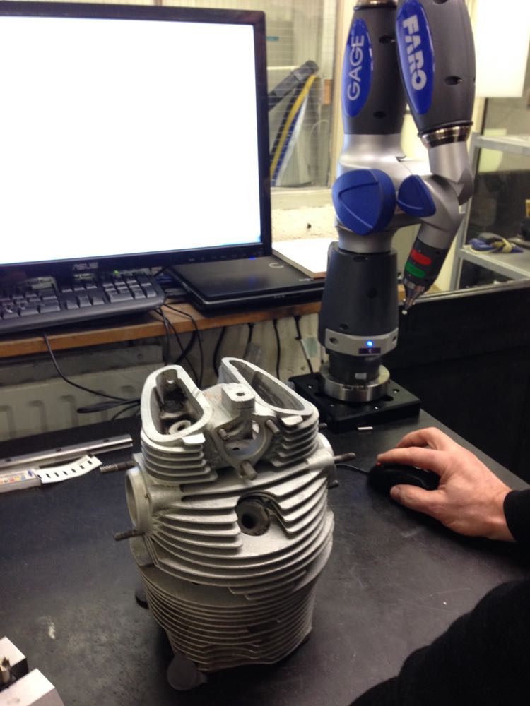
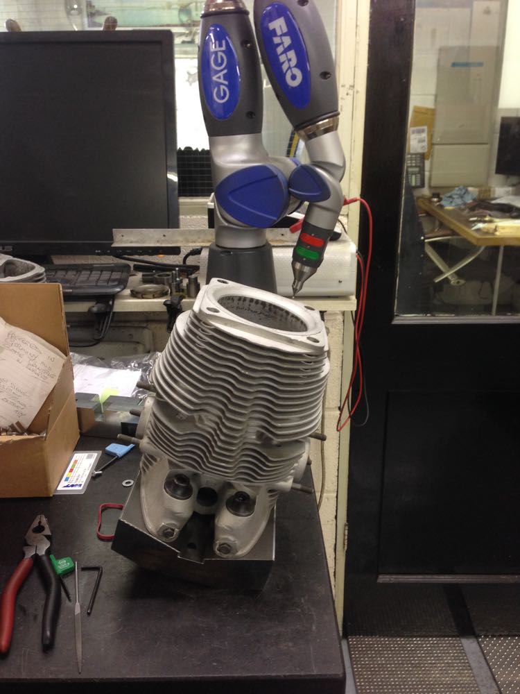
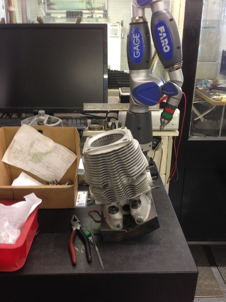
First up I had to make a jig for the CNC machine to hold the cylinder in the desired position, and so a flame cut lump of metal was ordered, then I needed the dimensions for the CAD model,and this is where a Faro arm comes in..
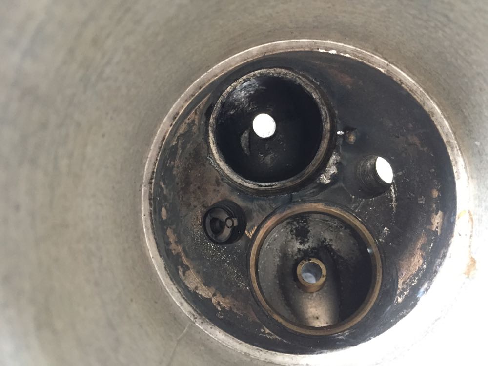
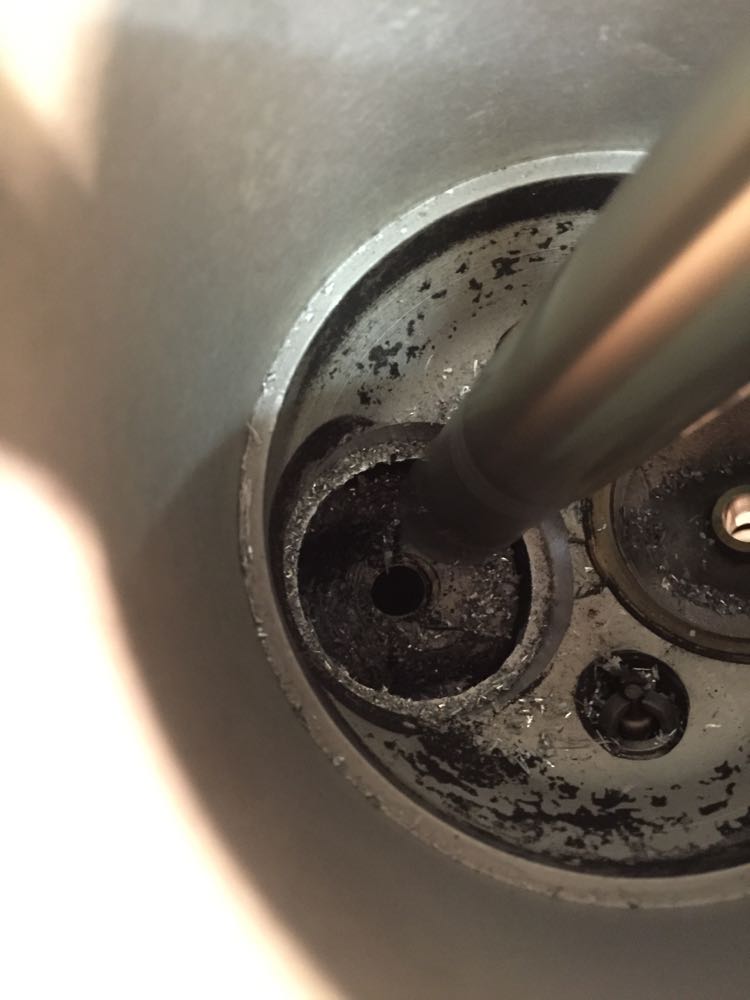
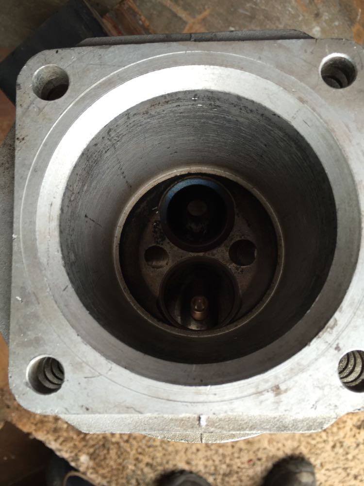
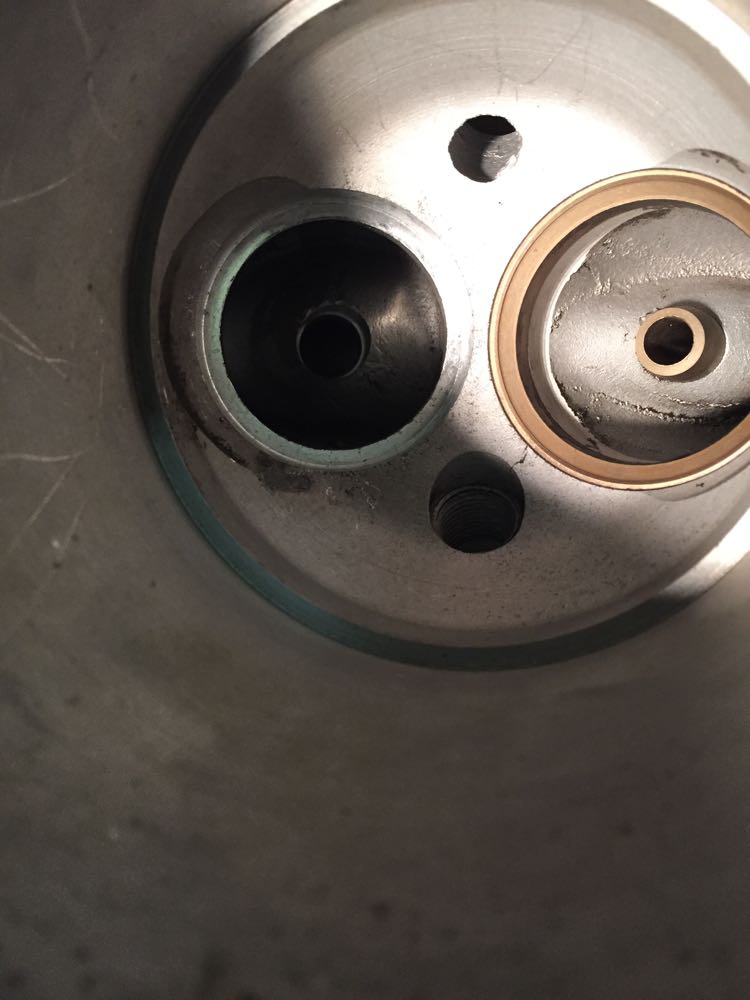
Next up a partial twin plugged cylinder had the standard exhaust seat removed as a precaution, as well as the valve guide later on. Notice all the deposits that oozed out of the seat removal process, which tells you this one was loose.
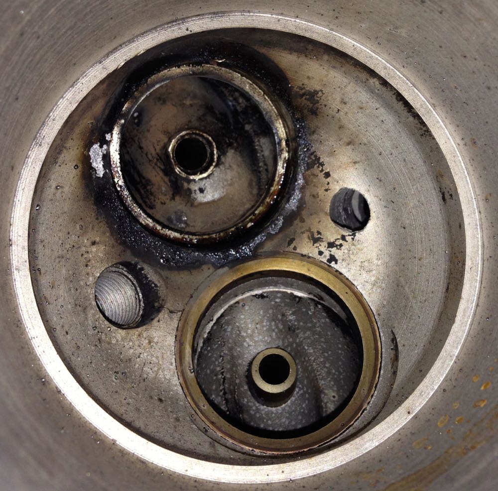
…and after a clean, and you can seat the exhaust valve seat recess fretting marks…
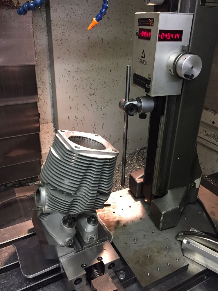
Now to create a test piece, to double check the accuracy of the jig, which had been CNC'ed from the CAD model I drew up previously.
Then time to double check the accuracy on the Faro again, but this is now September 2014. I have been working on other stuff whilst trying to progress this.
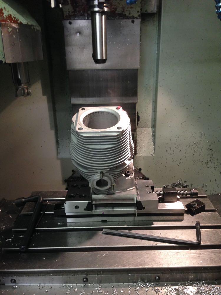
Another check a few weeks later, to make sure the milling machine can reach the bottom of the combustion chamber.
After all this there was a twist in the jig, and it needed to be machined, but at least it was spotted before any cylinders were done.
Finally in early December 2014, it is time to machine the new valve seat recess in the combustion chamber.
Then a quick check of the seat size, and a tweak to the final cut.
…and this is the finished seat recess cut into the head, with concentric valve guide hole done at the same time too.
After Christmas, it was time to make the guides and other stuff.
As these are all in one cylinders and heads, as in very deep, it's a mess trying to get down to weld and machine afterwards, and I thought it wasn't worth the effort. I found another cylinder that was a similar size with the liner removed, and I will update this.
First up I had to make a jig for the CNC machine to hold the cylinder in the desired position, and so a flame cut lump of metal was ordered, then I needed the dimensions for the CAD model,and this is where a Faro arm comes in..
Next up a partial twin plugged cylinder had the standard exhaust seat removed as a precaution, as well as the valve guide later on. Notice all the deposits that oozed out of the seat removal process, which tells you this one was loose.
…and after a clean, and you can seat the exhaust valve seat recess fretting marks…
Now to create a test piece, to double check the accuracy of the jig, which had been CNC'ed from the CAD model I drew up previously.
Then time to double check the accuracy on the Faro again, but this is now September 2014. I have been working on other stuff whilst trying to progress this.
Another check a few weeks later, to make sure the milling machine can reach the bottom of the combustion chamber.
After all this there was a twist in the jig, and it needed to be machined, but at least it was spotted before any cylinders were done.
Finally in early December 2014, it is time to machine the new valve seat recess in the combustion chamber.
Then a quick check of the seat size, and a tweak to the final cut.
…and this is the finished seat recess cut into the head, with concentric valve guide hole done at the same time too.
After Christmas, it was time to make the guides and other stuff.
The next generation engine
28/07/13 00:50
After the sudden failure of the 2014 engine on that uphill stretch of the M20, when Brian's 24CT was cruising at 6000 rpm on part throttle, I decided I needed to do some more development.
On examination the valve had failed and this was despite having adequate clearance, or so I thought at the time. Unfortunately, I was to discover that the valve train was rather inept at controlling the valves, and what had happened was the heavier exhaust valve had hit the piston, and on the affected cylinder it was more severe. I was only found out about this several months later, when I inspected the other cylinder.
So what were the plans for the 2016 engine.
1. Repair the damaged cylinder.
2. Investigate the piston to valve clearance, and increase this.
3. Investigate the valve gear return spring tension.
4. Fit the later programmable electronic ignition with multi toothed trigger wheel
5. Refine the double sump & filter set up.
6. Bench test the engine, prior to installing in the car.
