Panhard ignition - Imfsoft Master Mini 3TCI
Saturday 20 September 2014 Filed in: Panhard Ignition
After getting back from Belgium, I started to revisit the Master Mini 3TCI that was working on the test rig before I left.
Unfortunately, I had a firmware glitch that was stopping it writing to the ROM chip, aka the “FLASH” in Czech speak, but of course I didn’t know this. I had uploaded the latest version previously, but as I was getting frustrated, I resurrected a Windows 7 laptop and installed the Imfsoft software direct from the website, and the pages that referred to the Master Mini 3TCI. Upon opening it, the MASTER software looked different, so I reset the wheel parameters, and wrote to the RAM & ROM, disconnected the power, and read the ROM. It stayed the same, whereas the MacBook running XP SP3 in Parallels 9 was corrupting the unit. I was getting loads of “-128” values in boxes, when previously they were blank.
After doing a few oscilloscope traces of the trigger wheel in action at various speeds, and having no problems, I rebooted the MacBook with the same firmware and wrote it to the MASTER Mini...voilà c’est parfait.
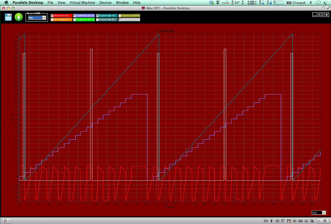
Here’s a few screenshots from the MacBook, at different speeds. the lowest recorded cranking speed was 40 rpm!
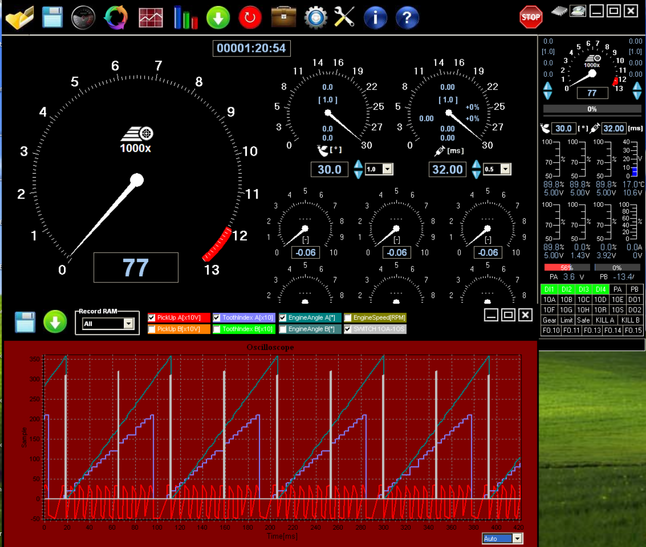
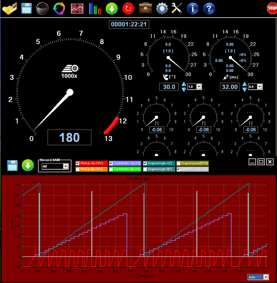
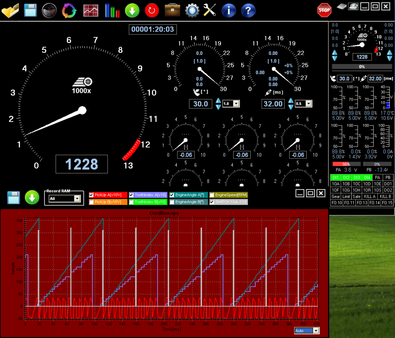
The red trace at the bottom is the trigger wheel going past the sensor, the white columns are the ignition events for the coil switching, so you can see two per revolution. So it’s all looking good again. Next test is check at what range of air gap I can tolerate, and not lose reliable triggering, but that’ll be another day.
Unfortunately, I had a firmware glitch that was stopping it writing to the ROM chip, aka the “FLASH” in Czech speak, but of course I didn’t know this. I had uploaded the latest version previously, but as I was getting frustrated, I resurrected a Windows 7 laptop and installed the Imfsoft software direct from the website, and the pages that referred to the Master Mini 3TCI. Upon opening it, the MASTER software looked different, so I reset the wheel parameters, and wrote to the RAM & ROM, disconnected the power, and read the ROM. It stayed the same, whereas the MacBook running XP SP3 in Parallels 9 was corrupting the unit. I was getting loads of “-128” values in boxes, when previously they were blank.
After doing a few oscilloscope traces of the trigger wheel in action at various speeds, and having no problems, I rebooted the MacBook with the same firmware and wrote it to the MASTER Mini...voilà c’est parfait.
Here’s a few screenshots from the MacBook, at different speeds. the lowest recorded cranking speed was 40 rpm!
The red trace at the bottom is the trigger wheel going past the sensor, the white columns are the ignition events for the coil switching, so you can see two per revolution. So it’s all looking good again. Next test is check at what range of air gap I can tolerate, and not lose reliable triggering, but that’ll be another day.
Comments
Panhard ignition update
Wednesday 17 September 2014 Filed in: Panhard Ignition
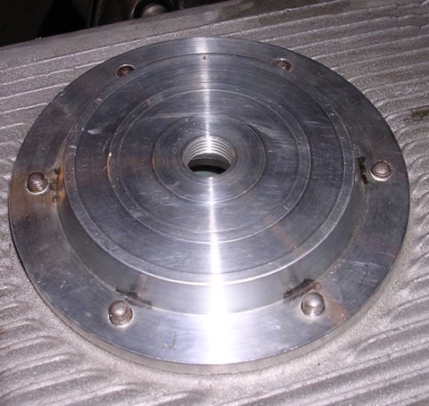
The ignition version of the timing cover has to be reworked, as Imfsoft do not make the Direct Ignition TCI model anymore, but a new unit called the Master Mini 3TCI. To adapt my existing two sensor covers I have made a blanking plug, and the thoughts at the moment are, that only one or no hole version of the cover will be produced, with a distinct possibility that the plain cover will be the ignition variant with a blanking plug fitted.
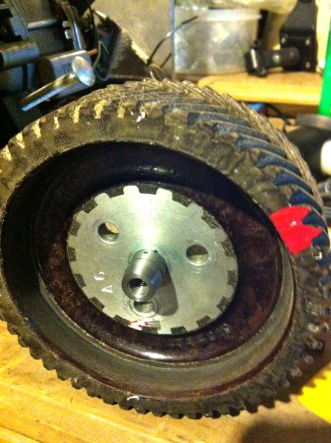
Here’s how it looks at the moment...the V pulley is an optional part, for those that cannot modify the front pulley themselves.
The timing cover is primarily a front seal upgrade option, so the ignition aspect is a secondary upgrade.
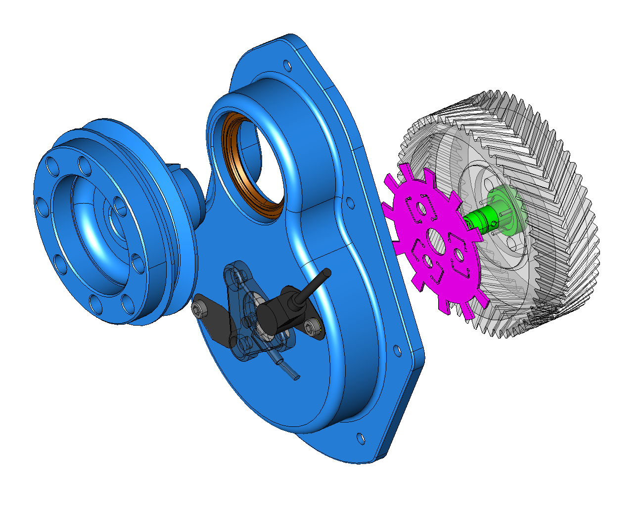
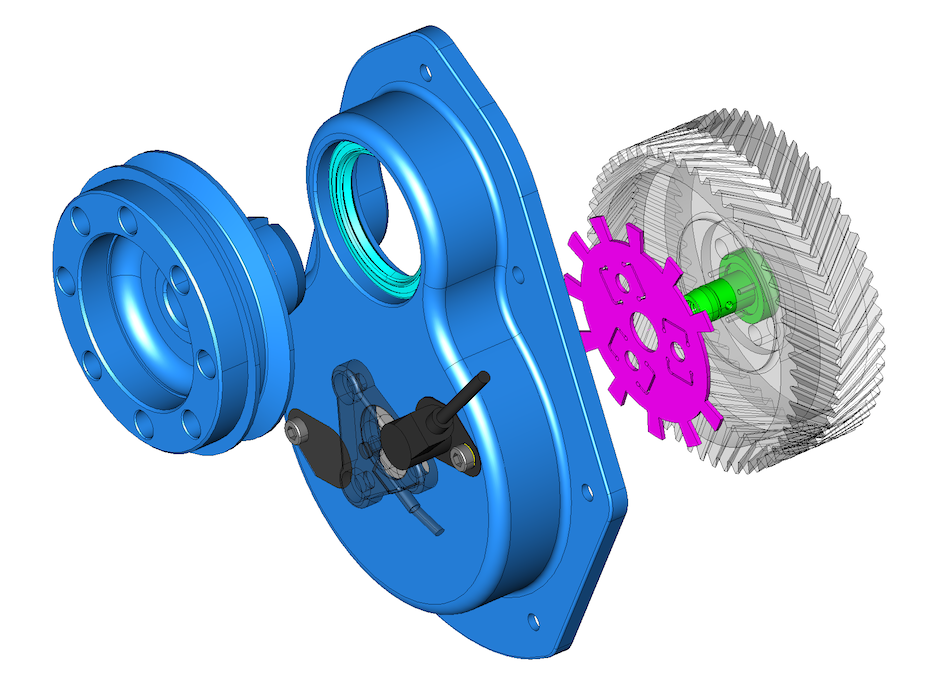
The Imfsoft Master Mini 3TCI has been bench tested and produces very good results, as can be seen here. The red waveform at the bottom is the teeth from the trigger wheel, the light blue “stairs” that step upwards are the incrementing trigger events, and these need to be regular steps. The diagonal greenish line is the processor interpreting the wheel, and the software is checking that these are the correct spacings. The white columns are twice per camshaft revolution and are the ignition events that trigger the coils.
At the moment, I don’t have a working engine, so I have fitted the Imfsoft to an MEP X2 recently. This used the earlier Imfsoft unit, but it has a very useful “dyno” function. The units are meaningless on the right hand side representing “Power”, but the shaping of the curve is representational. The first one is a standard Panhard M8S engine fitted with the original vacuum & centrifugal advance system, and the next curve is the first Imfsoft run where a modified advance curve affected the power output of the engine.
Early days yet, but interesting to say the least, and it backs up my earlier research with Ron Tyrrell’s PL17 where I modified the distributor. I could get a change in part throttle performance at the expense of full throttle or cruising. The mechanical system isn’t able to cope with the demands of the engine, whereas a correctly set up programmable system is.

Watch this space...
Panhard Ignition Improvements
Tuesday 04 June 2013 Filed in: Panhard Ignition
I have discussed the oil modifications in some detail over the years, but the next big area of improvement is the ignition.
The Panhard ignition was a distributor based system, that used a rotor arm to give a cylinder 1, cylinder 2 sequential output. There were two types of distributor fitted, vacuum only, and centrifugal & vacuum, but whatever type it is nowadays, the distributor will almost certainly be worn. I first noticed this in Ron Tyrrell’s car when I reversed the vacuum canister on his distributor to improve the running. Later I made a 123 ignition prototype distributor, but a board failure stopped the project.
It is quite common for this to be replaced with a Citroen 2CV coil, triggered by the points to create a wasted spark system, where cylinder 1 & 2 “fire” together, but the strongest spark is biased towards the cylinder with the most compression, which is full of the fuel air mix.
Other systems have been devised over the years of production, Hampe fitted twin contact breakers for twin plugging (although this was a wasted system for reliability), and some DB racers had a cam based triggering system from a special front cover. I found this out at Almen from Joel Brunel.
Whilst I was in Belgium, I got first hand knowledge of the distributor wear problem, when I was watching Stefaan timing up a MEP racer. This is basically a Tigre Panhard engine with a slightly different carburettor and manifold, but the distributor was a Ducellier vacuum & centrifugal type. He was running up the engine, setting the static advance based on the flywheel position, and getting a sluggish engine. In the end after disconnecting the vacuum, and measuring the centrifugal advance it was close on 28º and sticking, the vacuum was 23º, and static was an additional 21-31º. All these values are added together, so you could get close to 75º advance if you followed the manual.
Maximum advance for a Panhard engined racing sidecar running twin Amal carburettors was close on 32º, using high octane fuel, but burning modern pump fuel, the cars need a lot less than OEM. In fact, driving Sonia’s car & Brian’s whilst it was running, my static was around 10º to give nice off the throttle response, but at higher rpms, it could do with even less. Ron Tyrrell’s car has a manual advance and retard cable, a bit like a choke cable, which allows for variations to be made when running, and you do have to use it to make the engine more responsive under load. All of this tells you that the original Panhard ignition advance curve is not matched to present day fuels.
How would you go about to change this?
The obvious approach is modify the distributor, and Peter Breed does this, with a very nice 123 derived system. I actually did this years earlier, but the circuit board was too big, and so I had to make a new distributor casing. A distributor based system is still a good solution for some people, but it lacks accuracy, so modern cars use a more direct approach, mainly because of emissions, and the need to control things better.
Some earlier cars used a crankshaft sensor, using either the flywheel, a front pulley or a crankshaft web, and wasted spark coils. I did look at flywheel sensing for the Panhard engine, and it was the need to develop an easy to fit kit that negated this, so this is why I went down the modified pulley route, as shown below.
If you look at the components required to make an easy to fit kit, the cost is starting to go far too high, so I had to come up with a better idea. The biggest single flaw, was the lack of camshaft position sensing, which meant another set up to do this. On modern cars with overhead camshafts, it’s relatively easy to sense the cam lobe via a hole in the camshaft cover or a trigger wheel on the camshaft belt drive pulley, but on a Panhard pushrod engine, things are at first a little more complicated, as there doesn’t seem to be a suitable position to place one on the cylinder. It was only after I exhausted the camshaft sensor location possibilities, that I decided a trigger off the camshaft timing gear would be best and least expensive way to modify the ignition on these cars, because it would need only one part to be modified.
Camshaft triggering is often combined with crankshaft or flywheel triggering to make a higher level of precision on multi cylinder cars or motorcycles, and often this is used to create sequential information, so now the engine management knows what stroke the cylinder is on, which just replicates what the distributor cap and contact breaker system did originally. However, when you look at the spark events, you can use a simpler camshaft trigger will suffice, as the Panhard engine is unlikely to exceed 6500 rpm, and it only has two cylinder to ignite. It could even be modified further to provide more accurate rotational information, by fitting a toothed wheel, so it became a “no brainer” to not take this further.
However, I needed to identify the easiest area to locate a sensor and trigger, and it soon became apparent, that although I could modify the existing pressed metal timing gear cover, it would be a struggle for most people. After a large amount of CAD work, and experimenting with different sensor types, a new timing cover was developed, and this also includes a new front seal detail, but only after an easy mod to the front pulley. This new part creates an accurate highly reliable triggering system, but it does require the fitting of the aluminium camshaft gear aka “alu pignon”, as well as fitting a steel inner ring to the front pulley. It is a big step forward in modernising the engines, without detracting from their originality, and allows them to run better with modern fuels.
The latest version is here…this is designed for a MicroSquirt or Imfsoft Master Mini 3TCI
The part uses liquid gasket to seal the timing cover to the crankcase, and the original oil slinger parts, that diverted the oil from the piston ring oil seal are not required, a small laser cut spacer is used instead. The front crankshaft oil seal has an outer diameter of 65mm, which allows for a large variance in inner ring sizes to be used on the front pulley, as some Panhardistes have made modifications to this area already.
I recommend a 50 x 65 x 8 Viton oil seal, and a IR 45 x 50 x 15 inner ring.
Almen RIP 2013
Saturday 01 June 2013
Just a quick note to say thanks to all for making Almen 2013, the International Panhard Event such a pleasant experience. It was really nice to meet up with friends I last saw 10 years ago at Riems. Thanks to Sonia for letting me drive “Sophie” her 24CT, which was just as well as Sophie needed a little dose of spannering, but it was all resolved in the end. Next year is at Richelieu, France, but I have seen a couple of dates mentioned, one says Pentecost, the other 6/7 June 2014. I hope to be there in a Panhard again, but as always you travel hopefully.
Panhard Oil Lubrication Musings
Friday 15 March 2013 Filed in: Panhard Oil
I am writing this piece to try and get past some misconceptions some people seem to have about Panhard engines and their oil circuits. I will edit this over the next few weeks, and try and make this easier to grasp, and I hope to translate a little of this for my French friends who visit my website.
Panhard engines evolved over time, as they needed more horsepower and had to respond to service failures. The single biggest lubrication change came to the front cylinder crankshaft oil circuit, which was modified and adapted to cure a premature wear problem to this cylinders big end bearings.
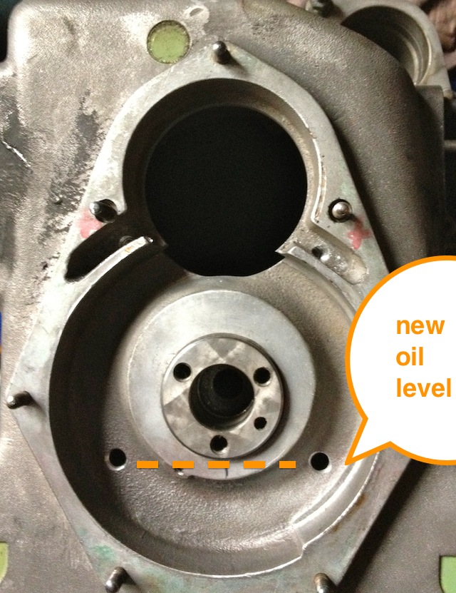
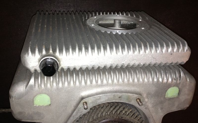
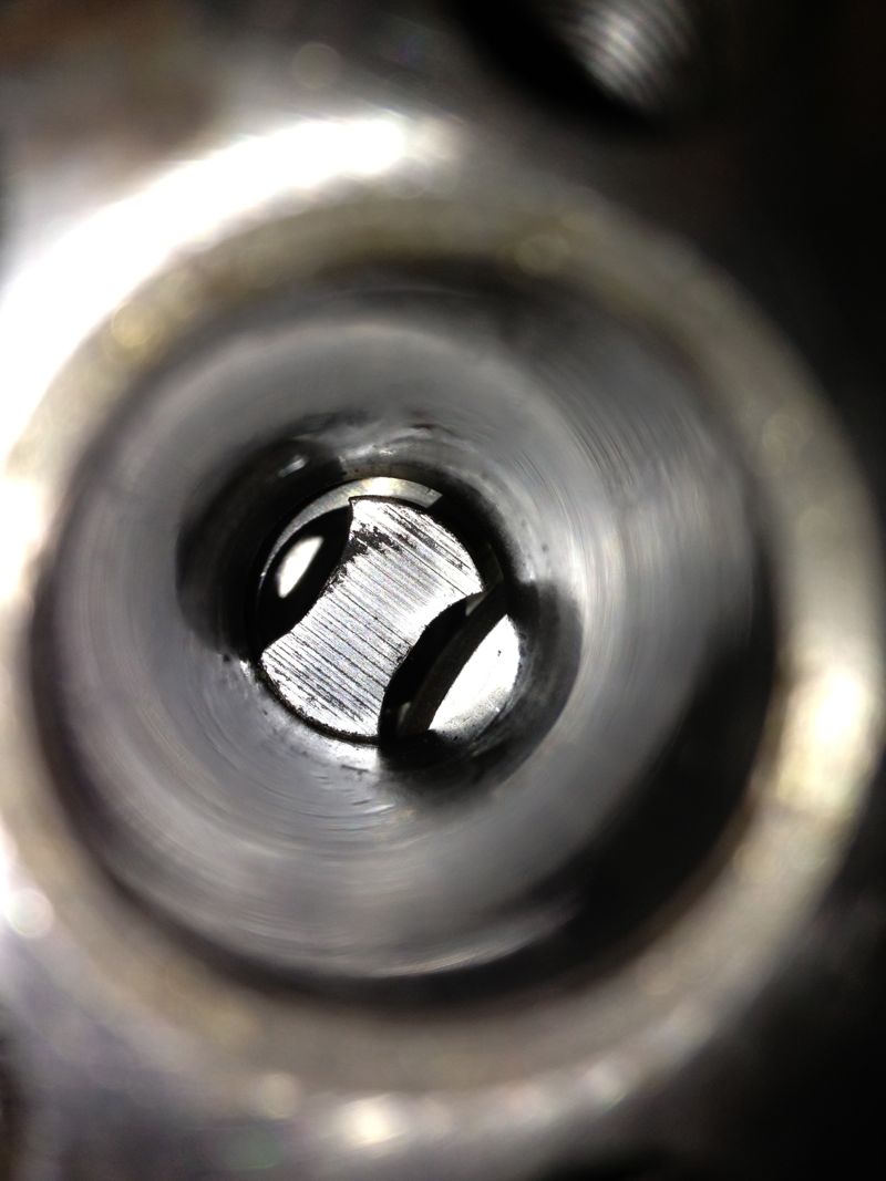
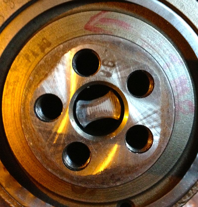
Originally the oil system was well designed, but a misplaced hole marginalised the oil supply at the front of the crankshaft compared to the rear. The oil supply to the timing gears was the problem, as can be seen in the picture below, labelled timing gear oil feed. This hole lowered the oil pressure to the slinger oil feed via the camshaft, so as the pump output dropped, the oil supply became deficient enough to accelerate the wear and cause service failures.
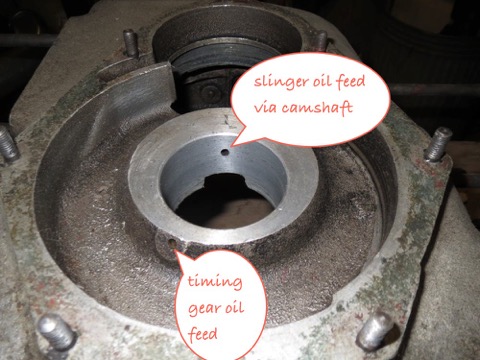
The later engines, had a modified oil delivery system, where the slinger oil feed was removed, and all the oil went into the timing gear case, and relied on the churning of the gears to splash lubricate and purge the oil into the slingers via two new high level holes. These are shown in the picture below, and labelled oil feed to slingers. The original drain holes that returned oil to the sump were filled in or not made.
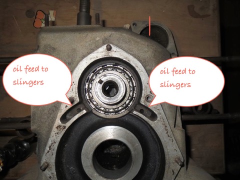
All that is needed to restore the oil to how it should have been designed, is to plug the timing gear oil feed and replace this with a central or common feed from the camshaft oil gallery. This is easily achieved by modifying or replacing the oil light piston with a bespoke design.
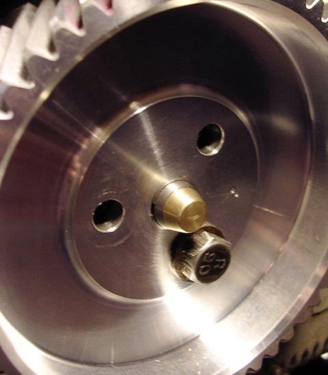
I had done this previously to various engines over the last few years, but refined it to include a bypass valve inside the oil light, so maintain a good pressure in the camshaft oil gallery. The small hole sprays an oil mist into the timing gear cavity, and lubricates the camshaft and crankshaft gear.
I also fitted a new nose to this, made of brass, but it wasn’t necessary, because there was no adverse wear to the other component.
UPDATE 15 September 2013
Lately, I have modified the design further by enlarging the hole, and using it as the oil pump pressure relief valve, that way the pumped oil isn’t wasted it used to lubricate the timing gears. The only thing I should point out, is that I create a lower oil return, so I don’t saturate the timing gears in oil and incur churning losses. Typical splash lubrication system, don’t immerse more than a third of the gear diameter.
I made the holes here on the 2012 engine, but I now make them slightly lower. As this was a M10 engine, I had to plug the slinger oil feeds with an M8 set screw & a dab of Loctite, and I also restored the original camshaft oil feed that passed through the crankcase, and made a new exit under the bearing. I also enlarged the hole slight at the camshaft interface to equalise the port timings front and rear, which is something Panhard never did.
Panhard engines evolved over time, as they needed more horsepower and had to respond to service failures. The single biggest lubrication change came to the front cylinder crankshaft oil circuit, which was modified and adapted to cure a premature wear problem to this cylinders big end bearings.
Originally the oil system was well designed, but a misplaced hole marginalised the oil supply at the front of the crankshaft compared to the rear. The oil supply to the timing gears was the problem, as can be seen in the picture below, labelled timing gear oil feed. This hole lowered the oil pressure to the slinger oil feed via the camshaft, so as the pump output dropped, the oil supply became deficient enough to accelerate the wear and cause service failures.
The later engines, had a modified oil delivery system, where the slinger oil feed was removed, and all the oil went into the timing gear case, and relied on the churning of the gears to splash lubricate and purge the oil into the slingers via two new high level holes. These are shown in the picture below, and labelled oil feed to slingers. The original drain holes that returned oil to the sump were filled in or not made.
All that is needed to restore the oil to how it should have been designed, is to plug the timing gear oil feed and replace this with a central or common feed from the camshaft oil gallery. This is easily achieved by modifying or replacing the oil light piston with a bespoke design.
I had done this previously to various engines over the last few years, but refined it to include a bypass valve inside the oil light, so maintain a good pressure in the camshaft oil gallery. The small hole sprays an oil mist into the timing gear cavity, and lubricates the camshaft and crankshaft gear.
I also fitted a new nose to this, made of brass, but it wasn’t necessary, because there was no adverse wear to the other component.
UPDATE 15 September 2013
Lately, I have modified the design further by enlarging the hole, and using it as the oil pump pressure relief valve, that way the pumped oil isn’t wasted it used to lubricate the timing gears. The only thing I should point out, is that I create a lower oil return, so I don’t saturate the timing gears in oil and incur churning losses. Typical splash lubrication system, don’t immerse more than a third of the gear diameter.
I made the holes here on the 2012 engine, but I now make them slightly lower. As this was a M10 engine, I had to plug the slinger oil feeds with an M8 set screw & a dab of Loctite, and I also restored the original camshaft oil feed that passed through the crankcase, and made a new exit under the bearing. I also enlarged the hole slight at the camshaft interface to equalise the port timings front and rear, which is something Panhard never did.
Panhard Engine Musings
Sunday 10 February 2013 Filed in: Blog Comments | Panhard Oil
The Panhard engine is intrinsically well designed, but the two things that could be improved with hindsight after having ceased production for nearly 50 years, is oil filtration & oil cooling. These two factors are fundamental in making a Panhard engine last longer, and the reason why they were vulnerable to failures in their production years.
Filtration is required because roller bearings have much less tolerance to particulates & contamination than the more widely used shell bearings, and fortunately tor Panhard owners there are various alternatives out there. Mr Guny and myself have developed suction variants, and later Mr Lauffenburger developed his pressure fed system. The latter is a comprehensive upgrade, and includes a new oil pump, the option to fit oil coolers and various other sensors.
It really doesn’t matter which one is used, as long as you employ some type of filtration. Historically, Panhard did fit a positive pressure filter off the RJH banjo feeds of the cylinders, but it was a partial system, because once the RJH system got up to pressure the main oil flow was through the camshaft gallery bypassing this arrangement.
Why did Mr Guny & myself both go down the suction route? I’d like to think we both recognised the oil flow of the Panhard engine is so low (compared to modern engines), that the pressure drop across a paper filter is negligible, and not a problem for the oil pump. This can be quite hard for people to understand, especially when surrounded by modern engines and all the technobabble that they are exposed to, but the simple fact is the Panhard engine is a low flow device, really elegantly designed, and it’s only when you start to use the engine harder in modern traffic conditions that the system gets stretched, and mainly because the oil gets too hot.
Again, there is a school of thought which says you should use OEM oils in your car even 50 years later, well that is nonsense. Do you think oil technology has stood still in that time, so don’t expect your engine to suffer the old stuff either. In todays driving conditions, on a summers day going down the motorway, you will exceed the oil temperature limits of straight mineral oil frequently, however around town stuck in traffic with little airflow only occasionally.
What does this tell you? Simply, the engine cannot dissipate the heat in the oil. So how to do something about this? Heat dissipated is proportional to the flow rate, the surface area available, and also the quantity, because a small kettle boils faster than a big one. The complicated way (and not dissing anyone) is fit an oil cooler (more surface area), and a bigger oil pump and tackle the flow side of the equation, but the really smart option is to increase the oil capacity.
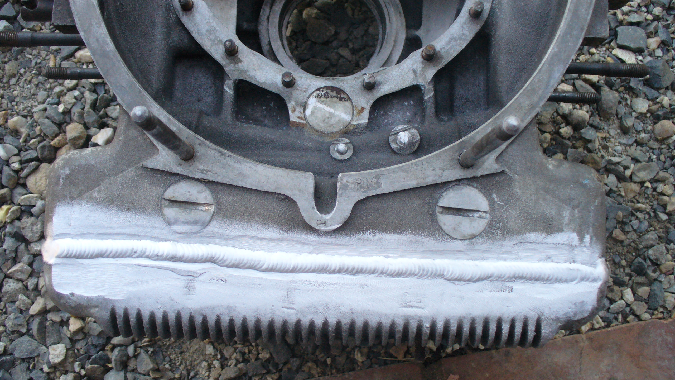
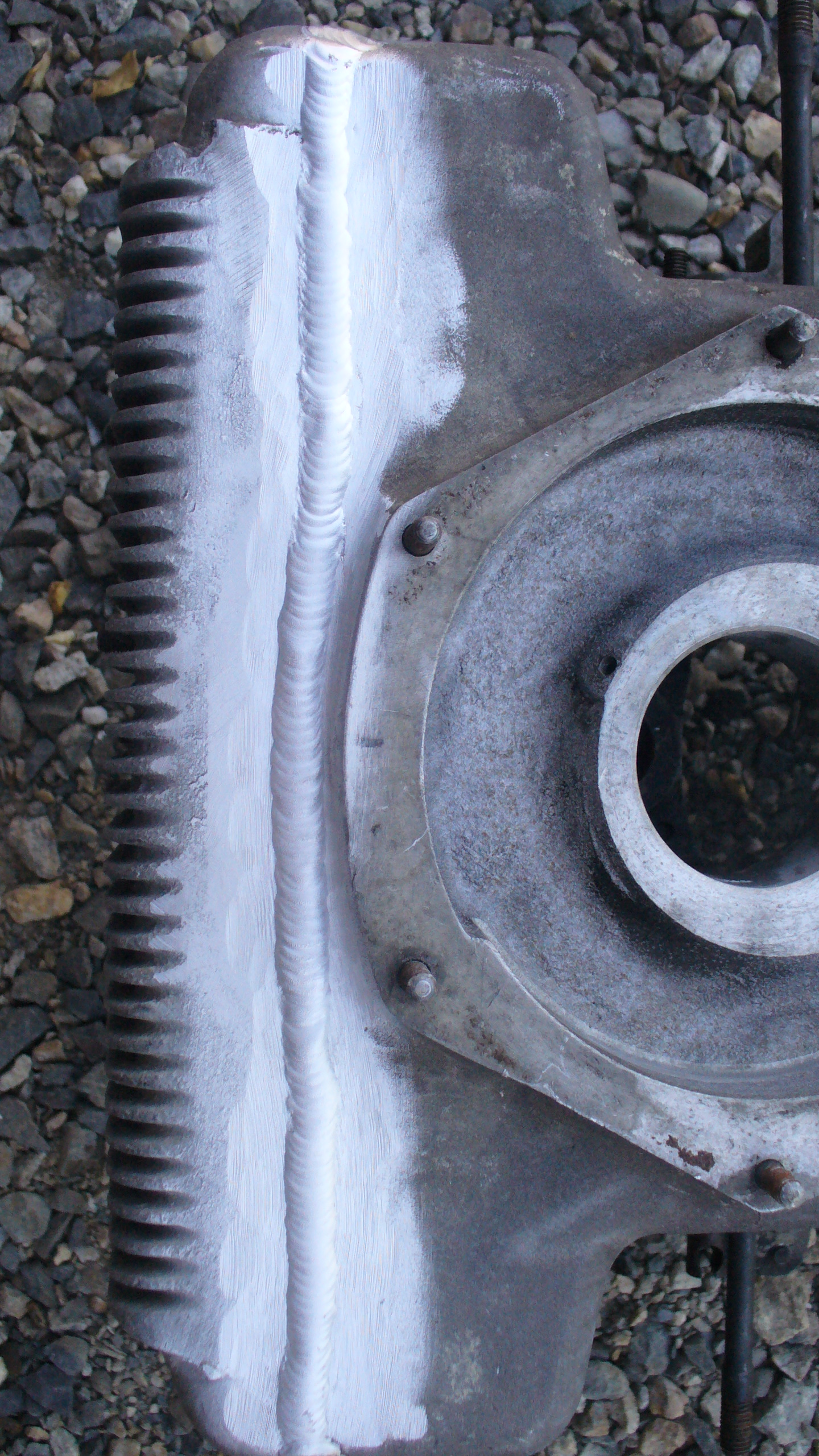
How you do this is down to the individual, one resourceful chap aka yves31 submitted these photos on the forumpanhard.free.fr. If you look closely, he has removed a thin portion off the base of his existing engine, taken another engine, and removed the sump with a higher cut line, and TIG welded the two together. All of this adds 21mm to the depth, and gives 1.3 litres of extra capacity. It is an excellent idea, but probably not easily achieved by typical owners, needs a donor crankcase, some skilful welding and requires a total stripdown of the engine. The last point is only valid if you have an engine in good condition.
The next way, is to take a leaf out of the competition engines of the 1950’s and fit a double sump or double carter. The beauty of this system is it is easily fitted, has more surface area, yet still adds about 1.1 litres of extra oil, and can be purchased for around €140, without the oil pump adapters. This is the system that I fitted to Ron Tyrrell’s car, along with a modified oil filter kit, that placed the filter inside the crankcase, and not externally, like my other versions, which meant the extra depth of the sump (44mm) was about the same as the screw on oil filter conversion.
In tests, the oil temperature of his car dropped significantly around town, rarely went above 80ºC in drives around the rural roads. In motorway work this summer on the way to the Citröen Rally at Harrogate where 130ºC had been seen in the sump previously, the temperature never went above 115ºC, and once the ignition timing and fuelling had been dialled in, the car was travelling faster and only recording 105ºC in the sump. Another observation was, as the car was being used the oil temperature rose more slowly than before, and also recovered, whereas I seem to remember in a fateful journey to Worcester one year in the same car (without the sump addition) as the day got warmer, the temperatures kept getting hotter, until a valve seat let go.
This reinforces the best way to cool the engine is with more oil capacity, however fitting an oil cooler has other benefits in that it can be used as a heating matrix for demisting & added warmth without the oily whiffs off the air fed heating system at present.
One of the problems some Panhard owners have with filtration is the ground clearance issue, which is really is a non issue on Dyna X, PL17 & 24 models, because the exhausts hang down further either side of the sump plate, where typically an aftermarket filter is located. If adding a double sump or anything else it would be best to fit an internal filter, with the flatter sump plate, and although filter changes are not as quick, if ground clearance is an issue to the owner, an internal filter would be the best option.
Over the next few months I will be making a revised internal filter kit for the double sump variant, based on the Ron Tyrrell prototype, as Brian’s engine needs one and so does a friend in Belgium, but I am just rejigging the CAD files, as this latest double sump, has a smaller hole on the underside than previously. Ideally, I’d like to make one new sump plate fit both versions, but even though it would compromise the ground clearance by only 13mm, it’s probably better to make two different versions to negate criticism.
Filtration is required because roller bearings have much less tolerance to particulates & contamination than the more widely used shell bearings, and fortunately tor Panhard owners there are various alternatives out there. Mr Guny and myself have developed suction variants, and later Mr Lauffenburger developed his pressure fed system. The latter is a comprehensive upgrade, and includes a new oil pump, the option to fit oil coolers and various other sensors.
It really doesn’t matter which one is used, as long as you employ some type of filtration. Historically, Panhard did fit a positive pressure filter off the RJH banjo feeds of the cylinders, but it was a partial system, because once the RJH system got up to pressure the main oil flow was through the camshaft gallery bypassing this arrangement.
Why did Mr Guny & myself both go down the suction route? I’d like to think we both recognised the oil flow of the Panhard engine is so low (compared to modern engines), that the pressure drop across a paper filter is negligible, and not a problem for the oil pump. This can be quite hard for people to understand, especially when surrounded by modern engines and all the technobabble that they are exposed to, but the simple fact is the Panhard engine is a low flow device, really elegantly designed, and it’s only when you start to use the engine harder in modern traffic conditions that the system gets stretched, and mainly because the oil gets too hot.
Again, there is a school of thought which says you should use OEM oils in your car even 50 years later, well that is nonsense. Do you think oil technology has stood still in that time, so don’t expect your engine to suffer the old stuff either. In todays driving conditions, on a summers day going down the motorway, you will exceed the oil temperature limits of straight mineral oil frequently, however around town stuck in traffic with little airflow only occasionally.
What does this tell you? Simply, the engine cannot dissipate the heat in the oil. So how to do something about this? Heat dissipated is proportional to the flow rate, the surface area available, and also the quantity, because a small kettle boils faster than a big one. The complicated way (and not dissing anyone) is fit an oil cooler (more surface area), and a bigger oil pump and tackle the flow side of the equation, but the really smart option is to increase the oil capacity.
How you do this is down to the individual, one resourceful chap aka yves31 submitted these photos on the forumpanhard.free.fr. If you look closely, he has removed a thin portion off the base of his existing engine, taken another engine, and removed the sump with a higher cut line, and TIG welded the two together. All of this adds 21mm to the depth, and gives 1.3 litres of extra capacity. It is an excellent idea, but probably not easily achieved by typical owners, needs a donor crankcase, some skilful welding and requires a total stripdown of the engine. The last point is only valid if you have an engine in good condition.
The next way, is to take a leaf out of the competition engines of the 1950’s and fit a double sump or double carter. The beauty of this system is it is easily fitted, has more surface area, yet still adds about 1.1 litres of extra oil, and can be purchased for around €140, without the oil pump adapters. This is the system that I fitted to Ron Tyrrell’s car, along with a modified oil filter kit, that placed the filter inside the crankcase, and not externally, like my other versions, which meant the extra depth of the sump (44mm) was about the same as the screw on oil filter conversion.
In tests, the oil temperature of his car dropped significantly around town, rarely went above 80ºC in drives around the rural roads. In motorway work this summer on the way to the Citröen Rally at Harrogate where 130ºC had been seen in the sump previously, the temperature never went above 115ºC, and once the ignition timing and fuelling had been dialled in, the car was travelling faster and only recording 105ºC in the sump. Another observation was, as the car was being used the oil temperature rose more slowly than before, and also recovered, whereas I seem to remember in a fateful journey to Worcester one year in the same car (without the sump addition) as the day got warmer, the temperatures kept getting hotter, until a valve seat let go.
This reinforces the best way to cool the engine is with more oil capacity, however fitting an oil cooler has other benefits in that it can be used as a heating matrix for demisting & added warmth without the oily whiffs off the air fed heating system at present.
One of the problems some Panhard owners have with filtration is the ground clearance issue, which is really is a non issue on Dyna X, PL17 & 24 models, because the exhausts hang down further either side of the sump plate, where typically an aftermarket filter is located. If adding a double sump or anything else it would be best to fit an internal filter, with the flatter sump plate, and although filter changes are not as quick, if ground clearance is an issue to the owner, an internal filter would be the best option.
Over the next few months I will be making a revised internal filter kit for the double sump variant, based on the Ron Tyrrell prototype, as Brian’s engine needs one and so does a friend in Belgium, but I am just rejigging the CAD files, as this latest double sump, has a smaller hole on the underside than previously. Ideally, I’d like to make one new sump plate fit both versions, but even though it would compromise the ground clearance by only 13mm, it’s probably better to make two different versions to negate criticism.
Panhard Oil Light Piston
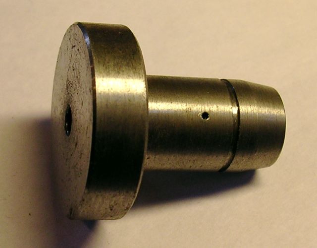
I have been asked to make an oil light piston for a friend in Belgium, and as promised here it is. This is only used when you modify the crankcase oil circuits, and although it is of similar dimensions to the OEM part, there is a built in oil pressure relief valve that only dumps oil through the side drilling to the timing gears when the camshaft gallery has a minimum of 30 psi or 2 bar pressure.
The diameter of the side drilling can be increased, but at the moment, there appears to be sufficient lubrication to the timing gears.
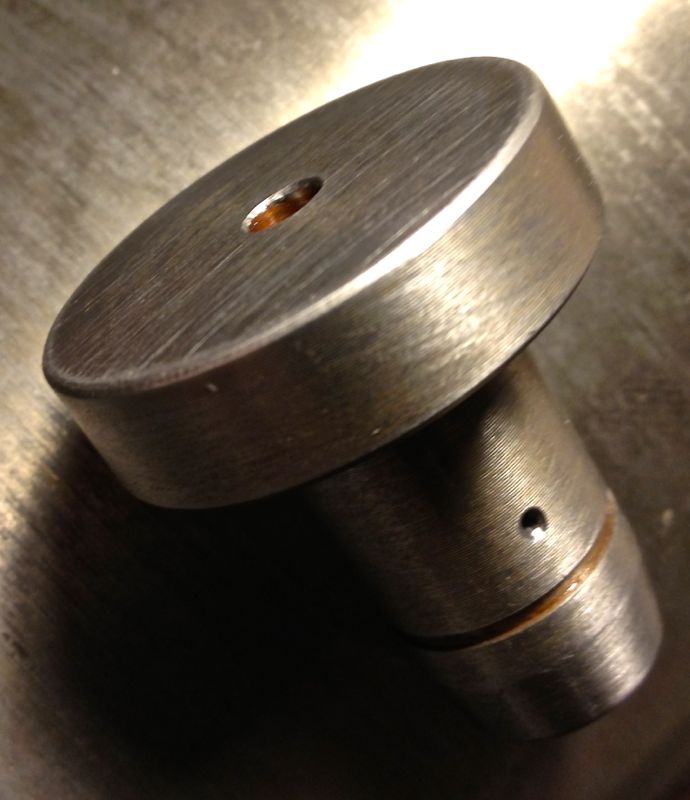
The circlip is not fitted in the following pic, and I haven’t rounded the corners at the tip. The evidence so far is it isn’t needed, but you can do this if you want.
The diameter of the side drilling can be increased, but at the moment, there appears to be sufficient lubrication to the timing gears.
The circlip is not fitted in the following pic, and I haven’t rounded the corners at the tip. The evidence so far is it isn’t needed, but you can do this if you want.
Panhard crankshaft jig
Sunday 13 January 2013 Filed in: Blog Comments | Panhard Crankshaft
I need to make a jig to hold the crankshaft on the mill bed. I could set it up using fee blocks, but I decided if I made a dedicated jig, I could reliably and consistently machine the two holes required for pinning 180º apart. If I machine to the same depth using the digital readout, then the crankshaft should stay in balance. After looking at the problem, I decided a session at the laser cutters would be more than adequate. This is what I had in mind in CAD, without the clamping mechanism being shown.
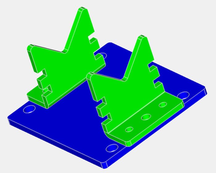
This is the first attempt, just waiting for a few fasteners, as the shop had closed by the time I picked the parts up.

I am going to modify it further with a quick change indexing system to give a 180º setting, but first I have to put it on the mill bed, and explore the tool path fit. The Clarkson MT40 collet holder is quite large, and I now need a slightly longer carbide slot drill to get machine the required hole depth for the dowelling process. the dowels are specially made for the job, and to aid removal, I have gone for the internally threaded type to aid crankshaft rebuilding operations.
It won’t be long before I can pin the crankshafts properly.
UPDATE I am going to use a small boring bar now, I tried with a slot drill, and it “walked” and the hole was too large!
This is the first attempt, just waiting for a few fasteners, as the shop had closed by the time I picked the parts up.
I am going to modify it further with a quick change indexing system to give a 180º setting, but first I have to put it on the mill bed, and explore the tool path fit. The Clarkson MT40 collet holder is quite large, and I now need a slightly longer carbide slot drill to get machine the required hole depth for the dowelling process. the dowels are specially made for the job, and to aid removal, I have gone for the internally threaded type to aid crankshaft rebuilding operations.
It won’t be long before I can pin the crankshafts properly.
UPDATE I am going to use a small boring bar now, I tried with a slot drill, and it “walked” and the hole was too large!
Panhard external oil filter conversion - screw on filter update
Wednesday 02 January 2013 Filed in: Blog Comments | Panhard Oil
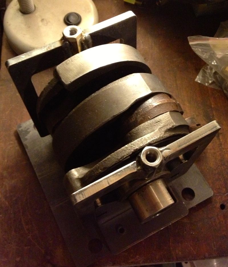
A lot of time has gone by since I did my first oil filter conversion, the first ten kits used a Champion F129 filter, whereas the later ones had a different thread and used a M20 x 1.5mm Renault Purflux filter.
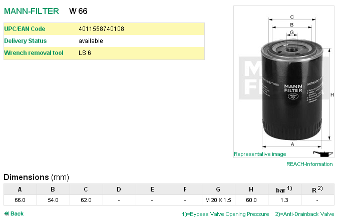
At the time the economics of making a special filter for the cars was out of the question, so it was necessary to remove the anti drain valve membrane fitted to the Purflux aka Renault Clio unit. Later on I made an internal filter version, but when I made a few external filter kits later I used a Mann Hummel W66. Details as below, but the picture is not representational, as it is only 60mm high. It is fitted with a bypass valve, which allows oil to flow should the filter clog up sufficiently to restrict the oil flow, but this is only really needed in high flow shell bearing crankshafts. In the Panhard engine, the low flow requirements and the low mileage usage they see means that the oil and filter would be changed before the bypass valve could operate, and besides the oil light would illuminate more frequently if this was happening.
One of the areas that was an improvement on the very first filter kit design was the dished area of the sump plate that received the filter cartridge was increased, so that meant there was more scope for larger diameter screw on filters.
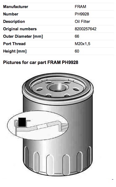
A UK PL17 owner, Gary Ockenden, who is involved in the motor trade recommended a Fram 9928, which is shown below (the picture is not representational), and this is an alternative for the Purflux LS924 & Mann Hummel W66.
Another filter that can be used is a Mann Hummel W87, but this is some 26mm taller than the W66.
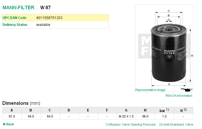
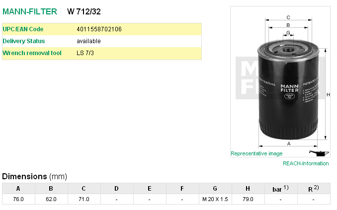
However the best filter, which has no bypass valve or anti drain valve fitted, so it is ideal on the suction side, is the Mann Hummel W712/32, but this is slightly taller by 19mm over the W66, and so better suited to the PL17 models. This model has a larger diameter as well, and so holds more oil.
The Mann 712/32 filter is also cross referenced to these numbers.
Ford 5022 739
Opel 650386
Vauxhall VOF114
GM 93156652 or 93156659
At the time the economics of making a special filter for the cars was out of the question, so it was necessary to remove the anti drain valve membrane fitted to the Purflux aka Renault Clio unit. Later on I made an internal filter version, but when I made a few external filter kits later I used a Mann Hummel W66. Details as below, but the picture is not representational, as it is only 60mm high. It is fitted with a bypass valve, which allows oil to flow should the filter clog up sufficiently to restrict the oil flow, but this is only really needed in high flow shell bearing crankshafts. In the Panhard engine, the low flow requirements and the low mileage usage they see means that the oil and filter would be changed before the bypass valve could operate, and besides the oil light would illuminate more frequently if this was happening.
One of the areas that was an improvement on the very first filter kit design was the dished area of the sump plate that received the filter cartridge was increased, so that meant there was more scope for larger diameter screw on filters.
A UK PL17 owner, Gary Ockenden, who is involved in the motor trade recommended a Fram 9928, which is shown below (the picture is not representational), and this is an alternative for the Purflux LS924 & Mann Hummel W66.
Another filter that can be used is a Mann Hummel W87, but this is some 26mm taller than the W66.
However the best filter, which has no bypass valve or anti drain valve fitted, so it is ideal on the suction side, is the Mann Hummel W712/32, but this is slightly taller by 19mm over the W66, and so better suited to the PL17 models. This model has a larger diameter as well, and so holds more oil.
The Mann 712/32 filter is also cross referenced to these numbers.
Ford 5022 739
Opel 650386
Vauxhall VOF114
GM 93156652 or 93156659
Panhard camshaft timing gears
Tuesday 01 January 2013 Filed in: Blog Comments
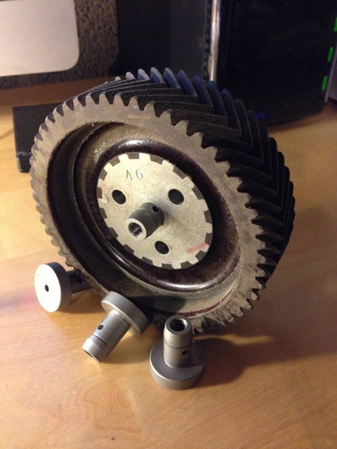
I was having a conversation with a fellow Panhard enthusiast, and he was querying the modifications to the timing gear oil level I make. At the end of the conversation, it was mentioned whether I had seen the modified DB timing gears, to which I said no. Later that day, I received some pictures via email.
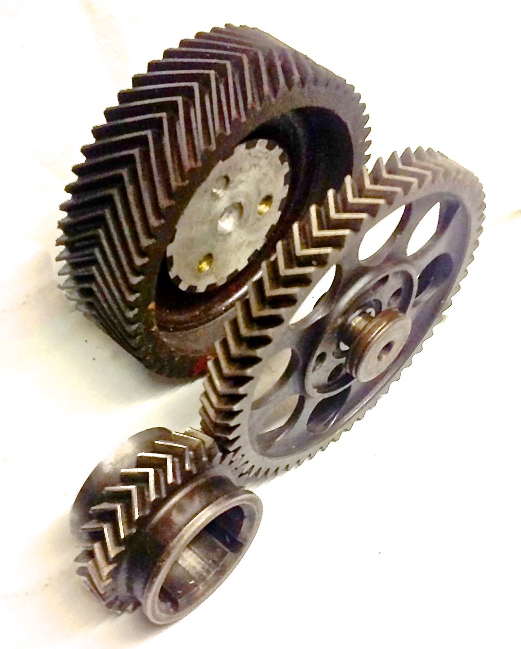
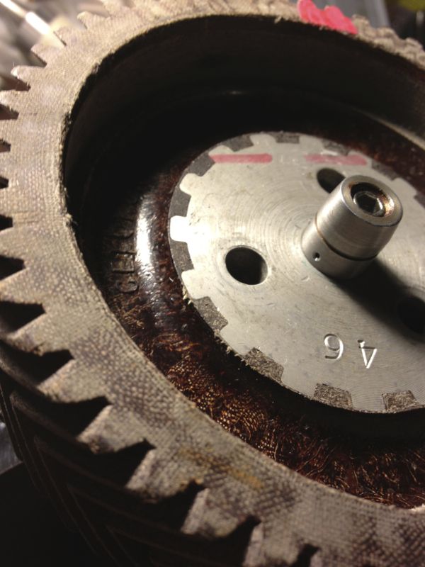
What’s really interesting, is I could never understand why the aluminium timing gear that replaces the fibre one was made the same width, as aluminium is so much stronger than the fibre aka Celeron gear. Looking at this DB gear, which is made in steel the racing guys took that to its logical conclusion, and reduced the width. This reduces the pumping losses too, as well as the inertial ones, so it seems there is scope for improvements here too.
Notice the extra mounting holes in the new gear, six versus three, which might have been some further camshaft timing adjustment mechanism.
Thank you Stefaan for the picture.
Panhard crankshaft truing
Sunday 04 November 2012 Filed in: Blog Comments
Too cold to work in the roof of the house first thing in the morning today, so for a few hours while it got warmer, I decided to make my crankshaft truing tool on the Elliot mill. I can’t do anything else until I collect the other liners and crankshafts, so it seemed fair to make a start on something else.
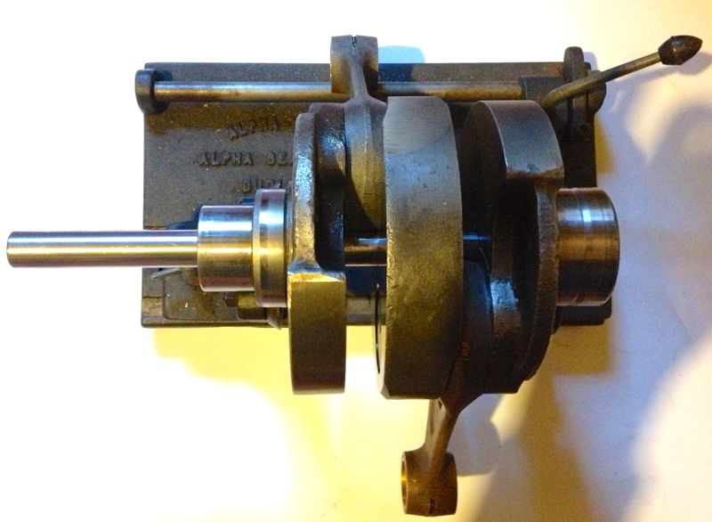
Several months ago, Martin McClarence had given me an ex Woody crankshaft to true up that had turned somehow.
When he installed this low mileage crankshaft (10 miles) into his engine, it decided to let go a little and break the piston ring seal and damage the timing gear cover. I knew it was bent because Martin couldn’t fit the rear bearing plate in the crankcase, when the crankshaft was installed in the front bearing, and this was confirmed by the wobble I saw on the Alpha crank truing rig. It is very awkward to true one of these cranks on a traditional crankshaft rig, which is why making the special tool is so beneficial.
After making my crankshaft tool, I decided to test it out on Martin’s crankshaft, and pleasingly it went down the middle until it hit the rear crankshaft web. A quick close up snap will show the tool and crankshaft hole are not concentric.
However, after looking at the crankshaft, a good swipe with a brand new #4 Thor from a decent height might suffice to put things right. It had to be bigger than my old crank bashing hammer, as these crankshafts have quite large pins, compared to the motorcycle crankshafts I have messed with in the past..Thor in right hand, crank in left, a couple of big swings and a few big hits later, and this is the result.
A quick check on the Alpha crankshaft truing rig, and it gets the all clear.
Now the question is do I leave it be, do i pin it or do I weld it with a pencil torch and TID set? I’ll let Martin make the decision.
UPDATE
He has and he’d like it pinning, so the saga continues...
Panhard bare cylinder isn't tapered (updated)
Friday 02 November 2012 Filed in: Blog Comments
I have long said that boring a tapered liner is extremely difficult, and I often wondered how Panhard did it, but today I found out for sure.
I have measured the internal diameters of a bare aluminium cylinder casting, and it is truly parallel internally. I have also measured a new old stock liner and this was parallel internally and externally, so it was suggested by me, that Panhard machined a tapered liner was the stuff of legends or folklore.
I actually surprised myself by accidentally stumbling upon a method of boring a tapered liner the other day, and although I might still do this using the boring bar directly, I didn’t think this is what Panhard did, as it’s not really a production method. So how else could this be achieved?
It was possible that Panhard used a tapered honing process, but again it’s way too slow and therefore probably not what Panhard did either.
I knew the cylinder finning and casting were tapered, and I wondered whether this fact was lost in translation when the cylinder was being described in the press releases, but then I had my eureka moment and I discovered an even easier way. I was drawing up a new cylinder in CAD looking at the original casting, and taking measurements, when it hit me.
The answer lies in the liner or sleeve is an interference fit in the cylinder casting, and depending on the interference, the strength of the cylinder casting (thickness of the walls) this determines how much the liner distorts, this distortion is what tapers the cylinder bore.
When the bare cylinder is warmed up the interference fit is lost, and the cold liner or sleeve is “dropped” in place, but when it cools the cylinder starts to squeeze the liner. However the cylinder walls have different thicknesses tapering from the bottom of the liner to the top, as in the picture below.
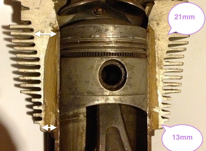
What this means is for a given interference fit along its length, the liner will be squeezed more at the top than the bottom, because the cylinder is much stiffer in compression at the top, and less stiff as the liner moves away from the top. The reality is on a cold bore today when it was 4ºC, the diameters measured across the liner from top to bottom are as shown.
3.3604” at the very top (closest to the combustion chamber in the above photo)
3.3620” in the middle of the liner, measured roughly in the middle of the cylinder casting.
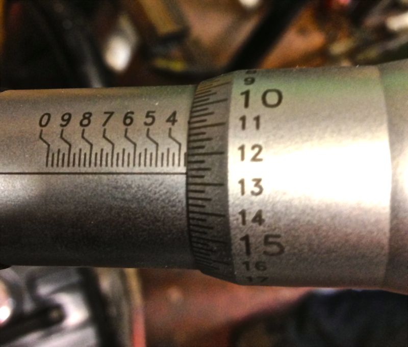
3.3626” in the liner, measured at the base of the cylinder casting.

Lastly, at the base of the liner skirt, which is the bit that isn’t contained by the cylinder casting, that is where the spigot goes into the crankcase, the actual machined bore diameter of 3.3670” is seen again on the micrometer.
There is a 0.007” variation on a cold cylinder from top to bottom, and no wonder people often said some engines were quiet and slow running, until they warmed up slightly!
The mystery as to how the cylinder bore becomes tapered is finally solved for me at least, and possibly a few others too.
It also means you can parallel bore the cylinder casting or sleeve, and you will not destroy the factory taper, but you must always take the liner or sleeve out of the cylinder casting otherwise you will.
If you make a larger bore engine using the standard cylinder casting & original interference fit, you will reduce the taper effect at the top, because you have reduced the wall thickness and compressive stiffness pro rata.
I am almost ready to machine the cylinders to suit the new pistons, but I need to explore a couple of other things first, namely how perpendicular is the bore, and how does the cylinder bore change with temperature versus the piston crown & ring body, which will establish the actual bore size required for the liner or sleeve.
UPDATE Saturday 3 November 2012
It seems that at about a cylinder temperature of 120ºC the bore is truly parallel, and approximately 0.007” larger at the combustion chamber end of the liner, than when it is cold.
I have measured the internal diameters of a bare aluminium cylinder casting, and it is truly parallel internally. I have also measured a new old stock liner and this was parallel internally and externally, so it was suggested by me, that Panhard machined a tapered liner was the stuff of legends or folklore.
I actually surprised myself by accidentally stumbling upon a method of boring a tapered liner the other day, and although I might still do this using the boring bar directly, I didn’t think this is what Panhard did, as it’s not really a production method. So how else could this be achieved?
It was possible that Panhard used a tapered honing process, but again it’s way too slow and therefore probably not what Panhard did either.
I knew the cylinder finning and casting were tapered, and I wondered whether this fact was lost in translation when the cylinder was being described in the press releases, but then I had my eureka moment and I discovered an even easier way. I was drawing up a new cylinder in CAD looking at the original casting, and taking measurements, when it hit me.
The answer lies in the liner or sleeve is an interference fit in the cylinder casting, and depending on the interference, the strength of the cylinder casting (thickness of the walls) this determines how much the liner distorts, this distortion is what tapers the cylinder bore.
When the bare cylinder is warmed up the interference fit is lost, and the cold liner or sleeve is “dropped” in place, but when it cools the cylinder starts to squeeze the liner. However the cylinder walls have different thicknesses tapering from the bottom of the liner to the top, as in the picture below.
What this means is for a given interference fit along its length, the liner will be squeezed more at the top than the bottom, because the cylinder is much stiffer in compression at the top, and less stiff as the liner moves away from the top. The reality is on a cold bore today when it was 4ºC, the diameters measured across the liner from top to bottom are as shown.
3.3604” at the very top (closest to the combustion chamber in the above photo)
3.3620” in the middle of the liner, measured roughly in the middle of the cylinder casting.
3.3626” in the liner, measured at the base of the cylinder casting.
Lastly, at the base of the liner skirt, which is the bit that isn’t contained by the cylinder casting, that is where the spigot goes into the crankcase, the actual machined bore diameter of 3.3670” is seen again on the micrometer.
There is a 0.007” variation on a cold cylinder from top to bottom, and no wonder people often said some engines were quiet and slow running, until they warmed up slightly!
The mystery as to how the cylinder bore becomes tapered is finally solved for me at least, and possibly a few others too.
It also means you can parallel bore the cylinder casting or sleeve, and you will not destroy the factory taper, but you must always take the liner or sleeve out of the cylinder casting otherwise you will.
If you make a larger bore engine using the standard cylinder casting & original interference fit, you will reduce the taper effect at the top, because you have reduced the wall thickness and compressive stiffness pro rata.
I am almost ready to machine the cylinders to suit the new pistons, but I need to explore a couple of other things first, namely how perpendicular is the bore, and how does the cylinder bore change with temperature versus the piston crown & ring body, which will establish the actual bore size required for the liner or sleeve.
UPDATE Saturday 3 November 2012
It seems that at about a cylinder temperature of 120ºC the bore is truly parallel, and approximately 0.007” larger at the combustion chamber end of the liner, than when it is cold.
Panhard bare cylinder isn't tapered
Saturday 15 September 2012 Filed in: Blog Comments
Panhard liners have had tapered bores since the early days. However when it’s time to rebuild them, I never found this out.
It was assumed by others, and I had no reason to question whether the liner was tapered internally, or perhaps the aluminium cylinder itself? The reasoning behind this was, if the aluminium cylinder was slightly narrower at the combustion chamber end, it would squeeze the sleeve and so make it tapered.
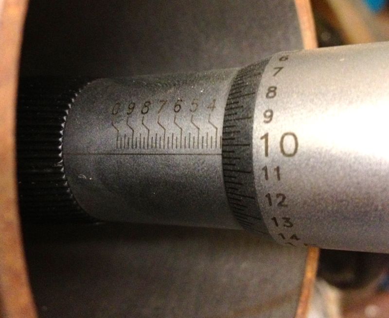
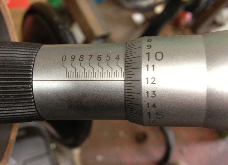
Yesterday, I got a Tesa three point bore micrometer in the post, and I was finally able to measure the internal bore of the aluminium cylinder.
I measured the bottom, middle and top of the bore of the bare aluminium cylinder, that’s without a liner or sleeve being fitted.
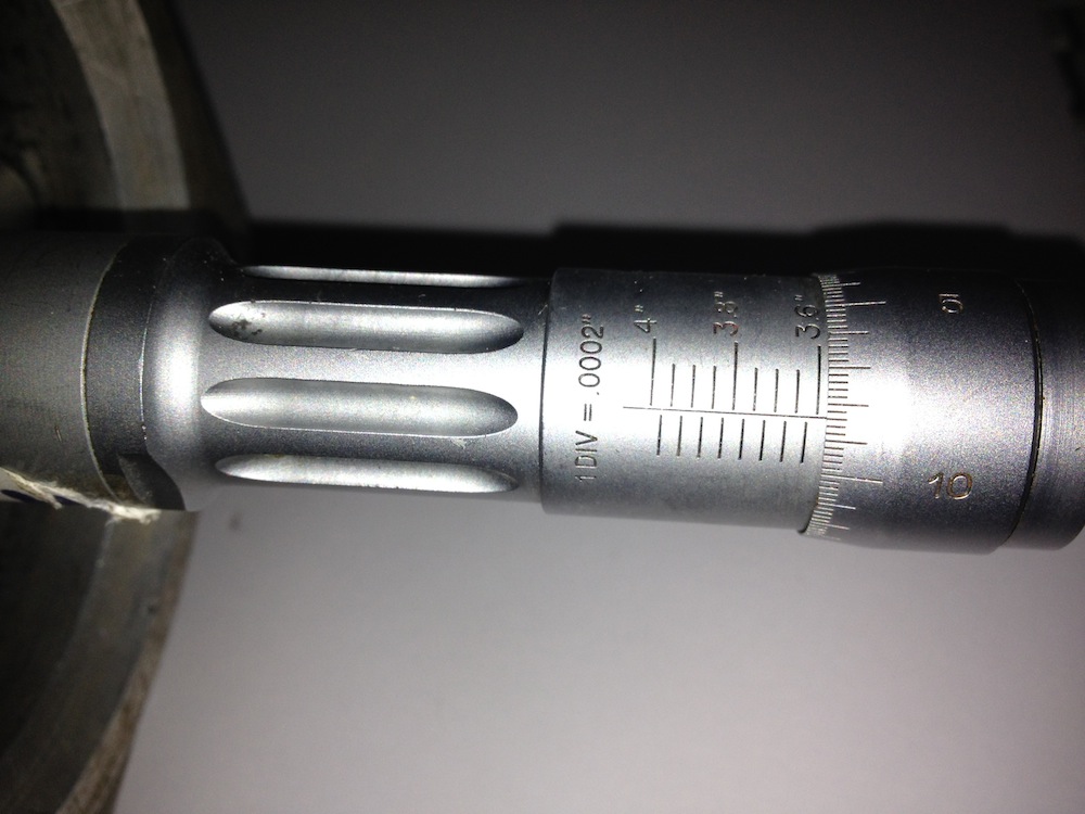
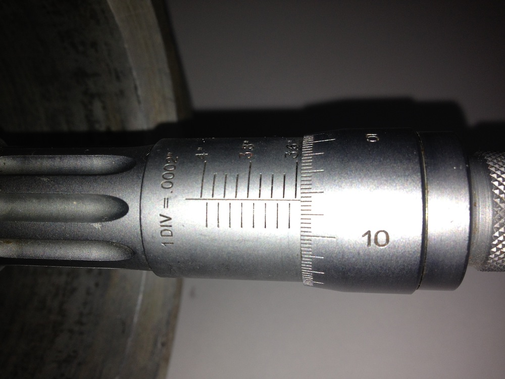
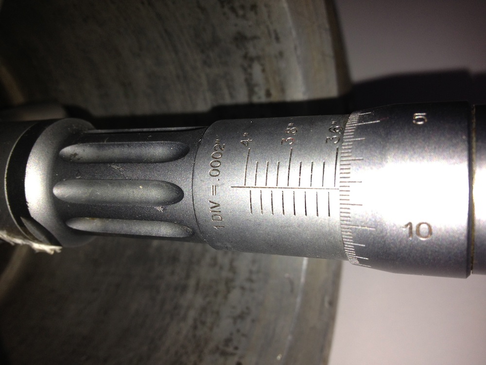
The divisions of the micrometer are 0.0002” or 2/10ths of a thou. There is no taper on the bare cylinder, so thats’s another bit of folklore or legend out of the way, and the only other way to achieve this would be to make the internal sleeve or cast iron liner taper outwards at the top, so that when it is inserted in the heated cylinder, upon cooling it compresses slightly more at the top than the bottom. Next up is to measure a few sleeves or liners and check whether this was done.
Interestingly the days of tapered bores were numbered with improvements in aluminium piston alloys and better machining, and Panhards have bigger issues with their piston design, so obsessing about having a tapered bore is rather irrelevant and futile.
UPDATE 23 September 2012
I measured the matching sleeve, taken from the aluminium cylinder above, and the external diameters are truly parallel, so I now know I will not have any issues when I bore the cylinder liner or sleeve.
It was assumed by others, and I had no reason to question whether the liner was tapered internally, or perhaps the aluminium cylinder itself? The reasoning behind this was, if the aluminium cylinder was slightly narrower at the combustion chamber end, it would squeeze the sleeve and so make it tapered.
Yesterday, I got a Tesa three point bore micrometer in the post, and I was finally able to measure the internal bore of the aluminium cylinder.
I measured the bottom, middle and top of the bore of the bare aluminium cylinder, that’s without a liner or sleeve being fitted.
The divisions of the micrometer are 0.0002” or 2/10ths of a thou. There is no taper on the bare cylinder, so thats’s another bit of folklore or legend out of the way, and the only other way to achieve this would be to make the internal sleeve or cast iron liner taper outwards at the top, so that when it is inserted in the heated cylinder, upon cooling it compresses slightly more at the top than the bottom. Next up is to measure a few sleeves or liners and check whether this was done.
Interestingly the days of tapered bores were numbered with improvements in aluminium piston alloys and better machining, and Panhards have bigger issues with their piston design, so obsessing about having a tapered bore is rather irrelevant and futile.
UPDATE 23 September 2012
I measured the matching sleeve, taken from the aluminium cylinder above, and the external diameters are truly parallel, so I now know I will not have any issues when I bore the cylinder liner or sleeve.
Panhard Engine Dyno Curves
Friday 24 August 2012 Filed in: Panhard Dyno
I had a nice telephone conversation the other day with a Belgian guy, who has forwarded on a few dyno curves from his engines and the Don Racine Panhard engined Aardvark special.
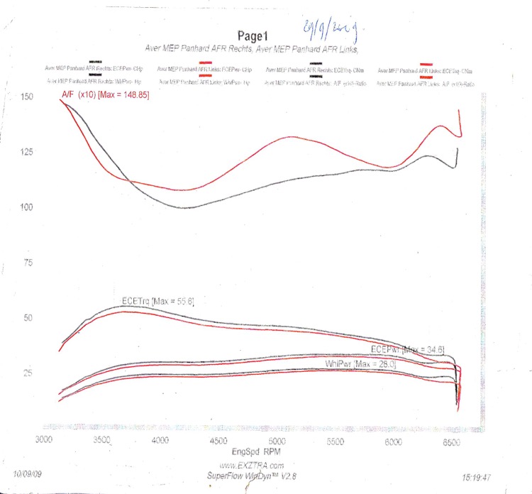
i have posted them here as a reference. I will add a few comments later, but for this Gawski tuned example, the upper curve is the Fuel/Air ratio, whereas the bottom three, are Engine Torque (calculated), Engine Horsepower(calculated), and Front Wheel Horsepower respectively.
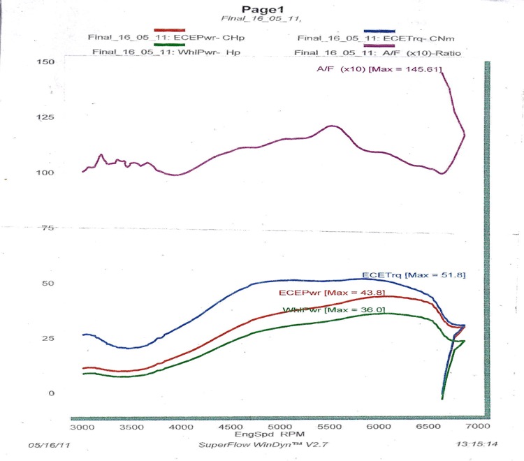
A standard MEP with a single Zenith NDIX carburettor, possibly a standard Tigre set up?
The Don Racine Aardvark example
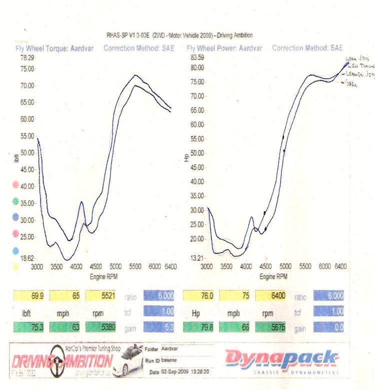
The horsepower numbers do not really matter unless they are on the same dyno, but the shape of the Torque curves is interesting.
i have posted them here as a reference. I will add a few comments later, but for this Gawski tuned example, the upper curve is the Fuel/Air ratio, whereas the bottom three, are Engine Torque (calculated), Engine Horsepower(calculated), and Front Wheel Horsepower respectively.
A standard MEP with a single Zenith NDIX carburettor, possibly a standard Tigre set up?
The Don Racine Aardvark example
The horsepower numbers do not really matter unless they are on the same dyno, but the shape of the Torque curves is interesting.
Panhard piston first batch delivered
Thursday 19 July 2012 Filed in: Panhard Piston
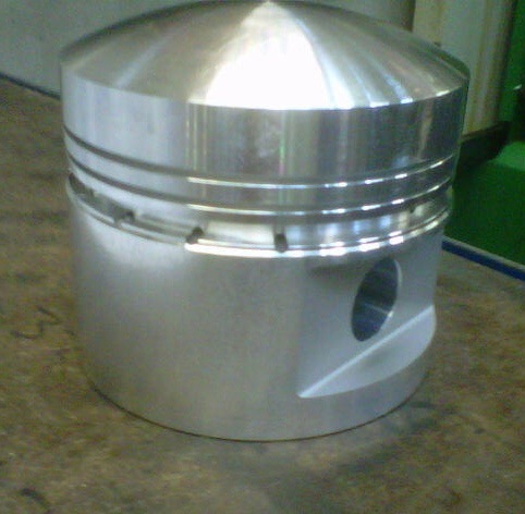
The pistons were delivered the other day, and here is the first picture of the bare piston, and below this another with the old piston for reference.
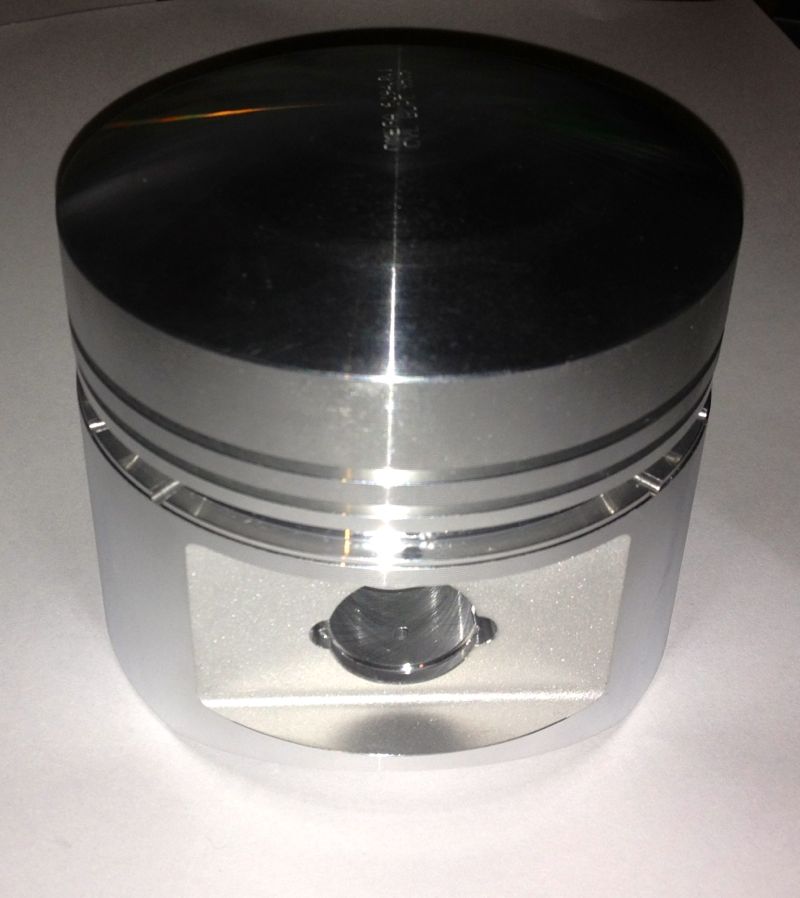
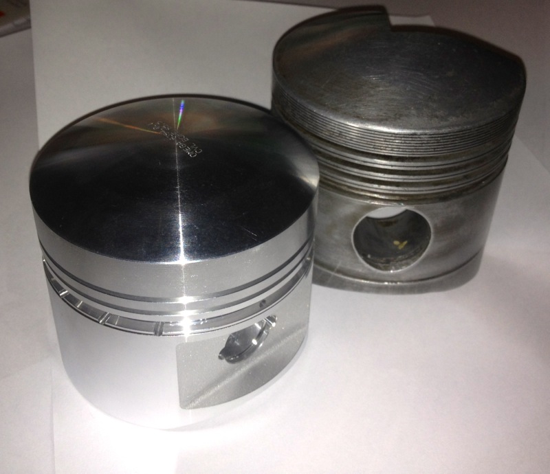
More pictures to follow, once I get back from my bike trip.
More pictures to follow, once I get back from my bike trip.
Panhard front pulley kit
Sunday 08 July 2012 Filed in: Panhard Parts
I sent a few links off to a few people and from their feedback and just to avoid any confusion, the new front pulley kit will only work with a revised seal arrangement. To update the seal you need to fit these components, which will be available assembled or as separate parts for future maintenance if required.
However, as the space available is limited within the OEM timing gear cover, the front pulley kit and the seal kit are designed to be an easy fit upgrade option, which is much the same philosophy as the filter kit upgrades, and an added bonus for those that are not removing the engine or doing additional works in this area. Initially fitting this kit might seem daunting at first, but it is really designed to be as foolproof as possible.
Obviously when the parts are made, I will post a video outlining the installations and use in situ photographs covering the assembly procedure.
ASSEMBLY PROCEDURE
First remove the old pulley after removing the fan and saving all the springs and wooden blocks. Leaving the timing gear cover in place, install the inner part of the pulley, which will consist of an aluminium centre and a steel inner ring already assembled together, engaging the key in the slot.
Next place the lightly oiled seal assembly, which will come ready assembled, over the timing gear front pulley aperture, and slide the seal over the inner ring until the steel ring is against the timing gear cover. The stainless steel ring should just be inside the opening, and now needs pressing into place.
Using the crankshaft front pulley bolt, and a spacer, press the seal assembly into position, by tightening the crankshaft bolt until the stainless steel seal adaptor is fully seated against the timing gear cover. The interference fit should be enough of an oil tight arrangement, but there is an O ring seal detail to make sure it is.
Remove the front pulley crankshaft bolt & spacer, and then place remaining part of the front pulley kit, which will be a sliding fit, into the steel inner ring. Next fit all the springs, wooden blocks, and other fan related parts and rebuild the fan assembly, not forgetting the V belt. Then refit the crankshaft pulley bolt and tighten to OEM torque figures.
Note, there is a dowel pin detail that aligns the front pulley in a set position, which will be used for those owners that want to fit a trigger wheel, whose primary purpose is to facilitate the use of third party ignition or modern engine management systems to their vehicle.
Panhard crankshaft pulley with trigger wheel (updated)
Friday 06 July 2012 Filed in: Panhard Parts
I have updated the CAD drawing to reflect my latest thoughts. I was looking for some oil pump parts and I came across a bag of Viton single lipped seals, which I recognised as some potential front pulley piston ring alternatives I bought five years ago. These seals were bought, as a continuation of the work I did with the rear bearing support seal adaptors, as I always intended to do away with the piston ring seals at either end of the crankshaft. I only made a few of these rear bearing adaptors, and I personally fitted a couple, and then sent some to the Netherlands, as well as a drawing to Germany.
There isn’t a seal that will fit directly into the timing gear cover, as it is a peculiar & unique diameter, so the idea back then was to make a carrier for the seal that would interface into the existing timing gear cover (same idea as the rear system I designed), which had the added bonus of not damaging the OEM timing cover too.This approach does mean a new front pulley assembly will be required, but this is in line with my philosophy of not damaging OEM stock when creating modified components. All the wearing surfaces are also easily replaced in years to come, and readily sourced, plus this system can recover worn timing covers.
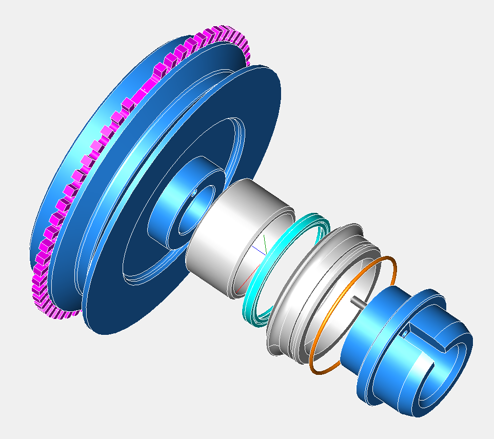
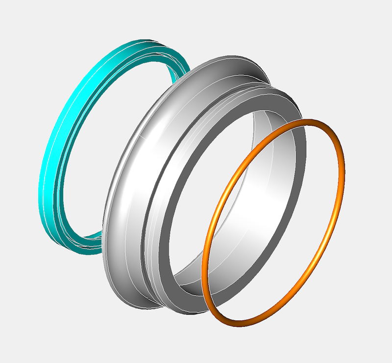
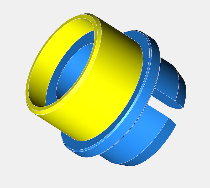
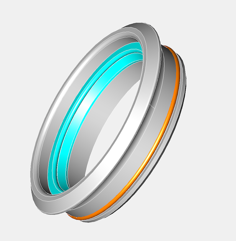
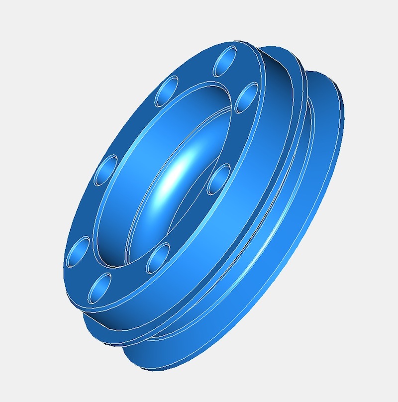
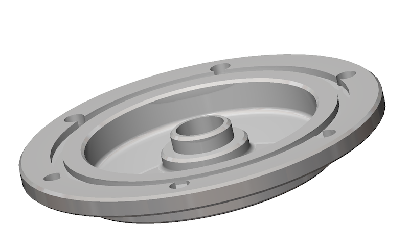
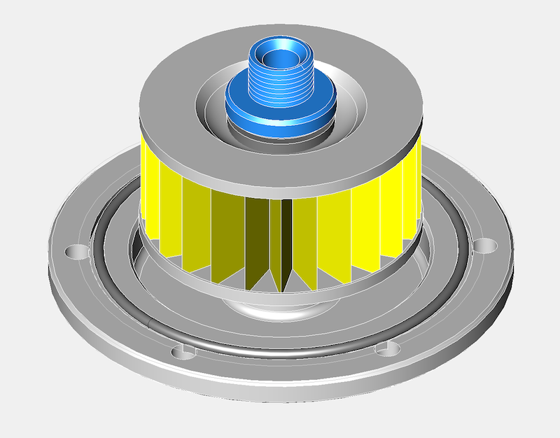
Today, I managed to get the timing gear cover seal diameter surfaces measured on a Elaton Coordinate Measuring Machine, so I now have a very precise idea of what diameter I need to make the new part so that it has a nice interference fit. This is the complete crankshaft conversion kit assembly pictured below.
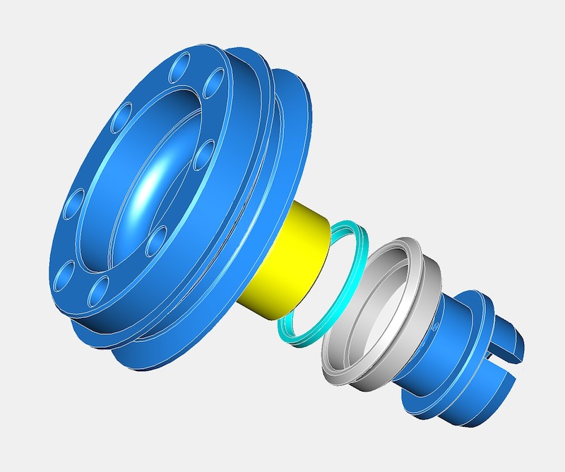
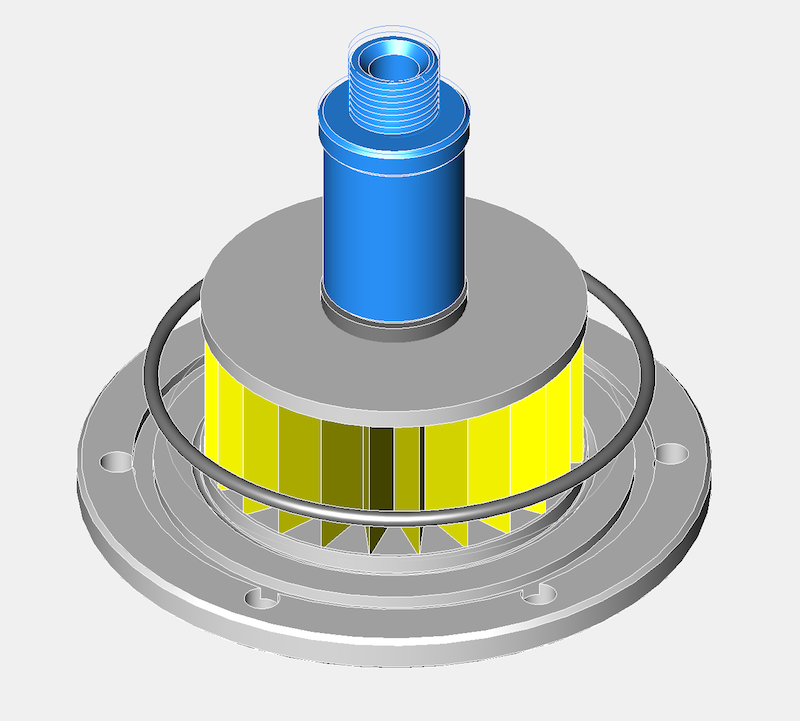
The grey part is the stainless steel seal carrier, and the cyan part the Viton seal. The yellow part is the steel inner ring, which is easily renewed if required, with the blue parts being the aluminium two piece front pulley components. These are located with a small dowel pin, however the parts are held together by the main front pulley crankshaft bolt.
It is necessary to make the parts this way to allow for DIY installations by Panhard owners, and it will be relatively straight forward to fit the conversion kit.
The picture below shows the optional trigger wheel version, which is needed by modern ignition or engine management systems, but fitting these is not for the faint hearted!
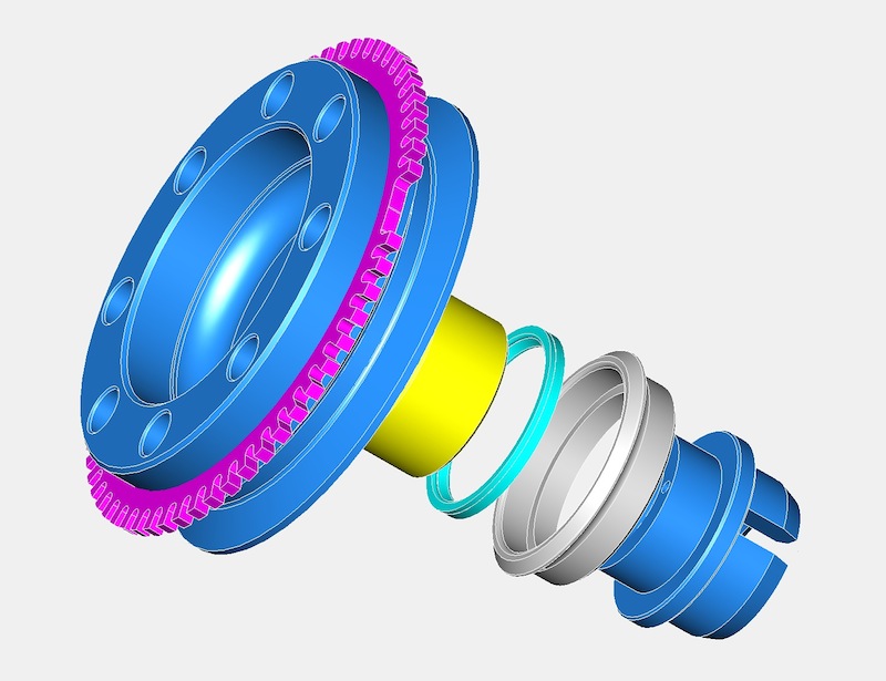
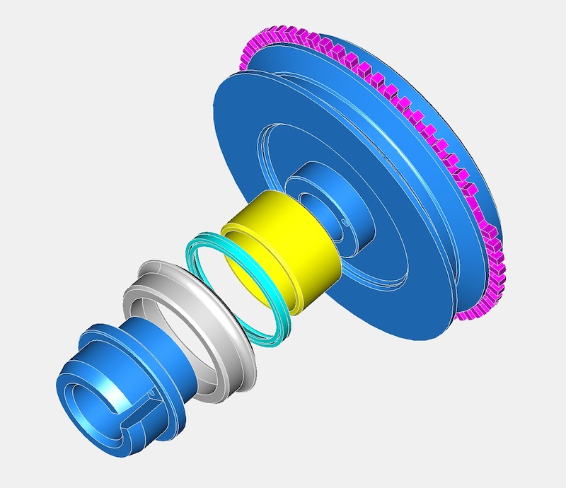
There are different tooth patterns available, but the one in the picture above is a 60-2 trigger wheel, commonly used by Bosch for VAG engines.
There isn’t a seal that will fit directly into the timing gear cover, as it is a peculiar & unique diameter, so the idea back then was to make a carrier for the seal that would interface into the existing timing gear cover (same idea as the rear system I designed), which had the added bonus of not damaging the OEM timing cover too.This approach does mean a new front pulley assembly will be required, but this is in line with my philosophy of not damaging OEM stock when creating modified components. All the wearing surfaces are also easily replaced in years to come, and readily sourced, plus this system can recover worn timing covers.
Today, I managed to get the timing gear cover seal diameter surfaces measured on a Elaton Coordinate Measuring Machine, so I now have a very precise idea of what diameter I need to make the new part so that it has a nice interference fit. This is the complete crankshaft conversion kit assembly pictured below.
The grey part is the stainless steel seal carrier, and the cyan part the Viton seal. The yellow part is the steel inner ring, which is easily renewed if required, with the blue parts being the aluminium two piece front pulley components. These are located with a small dowel pin, however the parts are held together by the main front pulley crankshaft bolt.
It is necessary to make the parts this way to allow for DIY installations by Panhard owners, and it will be relatively straight forward to fit the conversion kit.
The picture below shows the optional trigger wheel version, which is needed by modern ignition or engine management systems, but fitting these is not for the faint hearted!
There are different tooth patterns available, but the one in the picture above is a 60-2 trigger wheel, commonly used by Bosch for VAG engines.
Panhard oil filter variants
Sunday 01 July 2012 Filed in: Panhard Oil
I was updating a few pages and noticed that one of the oil filter prototypes was wrongly labelled. I was doing a retrospective update after finding some photos on another MacBook, when something didn’t add up, and it turned out that I’d been investigating an internal filter variant, as the modified Renault Purflux filters were being discontinued. At this point in time, there were not many alternatives out there, so I was experimenting with internal paper cartridge filters, that I had seen in a local motor factor, and I made a prototype based on my original baseplate.
However with hindsight, it was a red herring, because a few weeks later I found a Mann Hummel external filter, that was better than the Purflux derived Renault unit, but the internal solution still has merit, especially in a double sump increased oil capacity format, which is a necessity to reduce the engine oil temperatures and increase the oil quality.
After looking at this some more, I have decided to remanufacture this variant, as it offers a different solution for the factory Panhard car, and can be used with double sump versions too. It does not hang down as far as the cartridge, which is important because the ground clearance under the engine is reduced by 50mm after fitting the factory double sump. The actual ground clearance doesn’t change however, but fitting a sump or a cartridge filter appears to lower it in some peoples’ eyes.
Further plus points are, a magnetic sump plug can also be incorporated into the sump plate if required, the filter is freely available from motor factors in Europe, and the oil filter cartridge doesn’t need to be modified, which simplifies things further for the less dextrous. Technically it’s also easier for people to understand, as the paper filter is a straight swap for the original mesh filter, although the low flow rate & low pressure drop through a paper element principle still applies.
Latest CAD shown below, but it’s work in progress.
As I have been looking at the double sump variant for Brian Osbourne’s latest engine, it’s logical to try and use some of this for the next generation solution. I don’t have a double pump available at the moment, otherwise I would check whether I could use this new sump plate for the internal filter version with the double pump double sump application. I do know somebody with one, so I am going to take an internal filter and sump plate to their engine and see what is required, but it will have to wait until after the International Citröen Car Club 2012 Rally at Harrogate.
Latest thoughts in CAD for the double sump version, but only using the original oil pump, which is more than adequate assuming the crankcase oil circuits are modified. This version has a different pick up pipe and a flat not dished sump plate, so it will need two new parts.
Panhard piston update
Monday 11 June 2012 Filed in: Panhard Piston
Just had an update from the piston company, and they have sent me a grainy picture of the piston part finished.
The underside still needs machining, and the barrelling etc is still to do, but it’ll give an idea of how much shorter & lighter the piston will be.
The underside still needs machining, and the barrelling etc is still to do, but it’ll give an idea of how much shorter & lighter the piston will be.
Panhard musings
Monday 07 May 2012 Filed in: Blog Comments
I collected another Panhard crankshaft the other day to true up and lock in place, as it’s definitely not running concentric. It looks like the crank has turned ever so slightly on the crank pins and has a rather eccentric wobble.
As I am doing another crankshaft repair for Brian, I thought I’d compare the two, and at least this new crank confirms the other is too long between the bearings. In the discussions I had with the owner, I was bemused that somebody can spend a lot of money on bodywork and then baulk at the price of an engine.
Any engine that is going to get reconditioned will cost far more than swapping out for another. Its inevitable that the economics of doing so are questionable, but when you are faced with an older engine that is flawed, you’d think that would push the argument towards reconditioning, instead of just making do with any lump to hand.
In the case of the Panhard flat twin, unless you mod the lubrication circuits and increase the oil capacity you will be forever into a rebuild cycle, as these engines have some basic design faults. Panhard never had the money to eradicate these deficiencies, and whereas the engine initially was well designed, its’ subsequent development (to combat service faults) by different Panhard employees was not up to scratch as they missed the basics.
Unfortunately, very few people can see this point of view, and they seem to think you have to look to Panhards’ homeland for the best solutions, but there are no boundaries to good engineering or design. The UK has been a hub of motorsport development ever since Panhard started on their slippery slope to closure, and during this period British companies have seen dominance in World Rally cars and Formula 1. All this activity spins down to the lowest forms of motorsport, such as karting and clubman racing, and is also reflected in specialist educational courses available at the universities.
Nobody is suggesting that Panhards need F1 technology, but the companies that make parts for this industry have a huge expertise in material technology and manufacturing that can be applied to our engines, but only if you are open minded.
I hope over the next few months to surprise at least one person with the things I am working on, drop me a line if you are interested too.
Panhard Ignition Prototypes
Sunday 08 April 2012 Filed in: Panhard Ignition
I have had a nice update from Peter Breed, who says his ignition prototype is looking good. This will be a switchable two curve fully electronic set up that will be contained within the OEM distributor.
Like I said previously, I made several prototype ignitions in 2002, but the existing distributor couldn’t be used as it was too small a diameter to fit the circular board. My ignition prototypes were based on a 123ignition unit, sold as a Citröen 2CV Formula Bleu kit, pictured below, which incidentally was supplied by Ron Tyrrell.
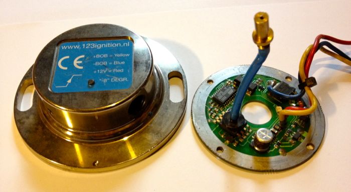
I soon made an adaptor to take the standard 2CV unit, as well as a new driveshaft complete with magnets, body shown below.

There is a big problem with this set up, as the circuits design rotation is the wrong way for the engine, which incidentally was a stumbling block for 123 designers at the time too. Fortunately I realised if I flipped the board the magnetic field would pass through the circuit board and the rotation would be effectively reversed, so I made a new model to test the idea, which was just a spacer sandwiched between the two previous halves, and a new spindle to take the magnets.
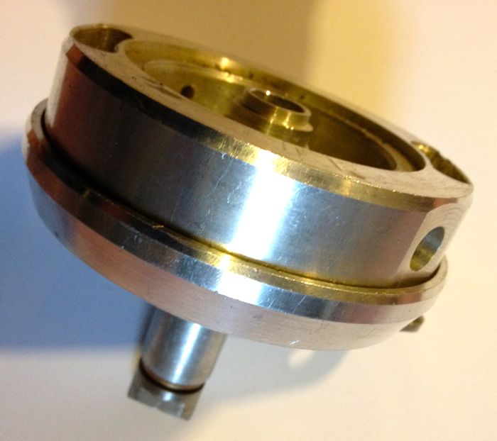
Now the board and magnets were in the base not the lid like with the 2CV set up, and also the 123 lid wasn’t needed. I had to put a bearing in the top, to stop the wobble about the spindle, so I ended up with a rather large lump initially.
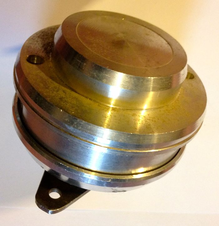
It wasn’t really surprising it ended up so large, but whereas I was making a conversion unit for the 123ignition kit before, I now had an opportunity to explore other options, and just use the basic component board.
So having tested the set up made a spark, using my motorised ignition rig, I made a new prototype, that ended being another version a couple of days later, but at least it was getting smaller. I incorporated the original 123 vacuum advance pick up into this version too, but the biggest drawback was I would have to up the ante again to fit the rev counter drive.
I wasn’t able to cut a gear drive for the tachometer drive like the SEV distributor needed and the economics were such that it wash’t viable to continue as it couldn’t meet the affordable target price.
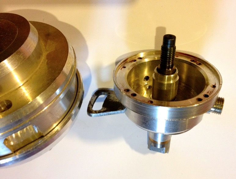
Still it was starting to look a lot more designed, and this is were I left off about 9 years ago.
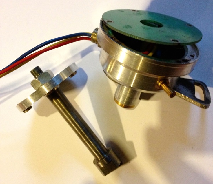
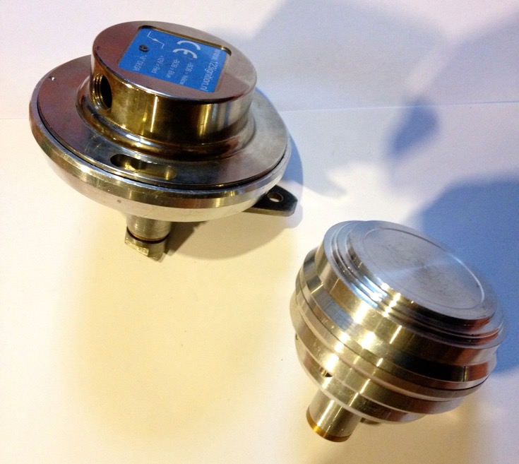
After the unit developed an electrical glitch, it was placed in a bag and left to gather dust, but by then the ignitions had taken a different turn with my MicroSquirt DIY EFI developments for the GTS1000. I would probably still retain the distributor for the tachometer drive, but use crankshaft based triggering off the front pulley, as it’s more precise and removes all the backlash and slop in the existing set up, which uses two sets of gears and two dog drives just to get to the contact breaker cam.
Interestingly, it has taken this long for 123ignitions to develop a smaller circuit board, but in the meantime they have developed a huge host of distributor based products for the more popular models out there, and these are quality products. I notice they have started to develop a DIY programmable interface for some of their products, but I don’t see any mention of the multispark set up one of the guys at 123 was working on at the time of my involvement.
Like I said previously, I made several prototype ignitions in 2002, but the existing distributor couldn’t be used as it was too small a diameter to fit the circular board. My ignition prototypes were based on a 123ignition unit, sold as a Citröen 2CV Formula Bleu kit, pictured below, which incidentally was supplied by Ron Tyrrell.
I soon made an adaptor to take the standard 2CV unit, as well as a new driveshaft complete with magnets, body shown below.
There is a big problem with this set up, as the circuits design rotation is the wrong way for the engine, which incidentally was a stumbling block for 123 designers at the time too. Fortunately I realised if I flipped the board the magnetic field would pass through the circuit board and the rotation would be effectively reversed, so I made a new model to test the idea, which was just a spacer sandwiched between the two previous halves, and a new spindle to take the magnets.
Now the board and magnets were in the base not the lid like with the 2CV set up, and also the 123 lid wasn’t needed. I had to put a bearing in the top, to stop the wobble about the spindle, so I ended up with a rather large lump initially.
It wasn’t really surprising it ended up so large, but whereas I was making a conversion unit for the 123ignition kit before, I now had an opportunity to explore other options, and just use the basic component board.
So having tested the set up made a spark, using my motorised ignition rig, I made a new prototype, that ended being another version a couple of days later, but at least it was getting smaller. I incorporated the original 123 vacuum advance pick up into this version too, but the biggest drawback was I would have to up the ante again to fit the rev counter drive.
I wasn’t able to cut a gear drive for the tachometer drive like the SEV distributor needed and the economics were such that it wash’t viable to continue as it couldn’t meet the affordable target price.
Still it was starting to look a lot more designed, and this is were I left off about 9 years ago.
After the unit developed an electrical glitch, it was placed in a bag and left to gather dust, but by then the ignitions had taken a different turn with my MicroSquirt DIY EFI developments for the GTS1000. I would probably still retain the distributor for the tachometer drive, but use crankshaft based triggering off the front pulley, as it’s more precise and removes all the backlash and slop in the existing set up, which uses two sets of gears and two dog drives just to get to the contact breaker cam.
Interestingly, it has taken this long for 123ignitions to develop a smaller circuit board, but in the meantime they have developed a huge host of distributor based products for the more popular models out there, and these are quality products. I notice they have started to develop a DIY programmable interface for some of their products, but I don’t see any mention of the multispark set up one of the guys at 123 was working on at the time of my involvement.
Panhard piston design finalised
Saturday 07 April 2012 Filed in: Panhard Piston
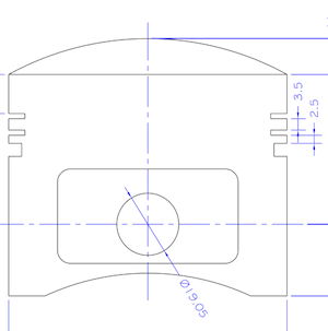
This is the latest iteration of the high compression Panhard piston that I am having made for Brian’s engine, and it will be substantially lighter than the OEM set up, but there is a slight compromise with the weight, because I want to use the standard cylinder and liner positions.
This piston will be used to modernise & improve the standard flat twin engine, and be a suitable replacement for the majority of the air cooled Panhard engines. It will need a new piston pin bush to cater for the standard crankshaft, but this is required whatever parts are fitted to the engine, as the original set up leaves little to be desired. This piston set will include a fully floating pin with improved lubrication to the piston pin bosses via cross drillings from the behind the oil control ring.
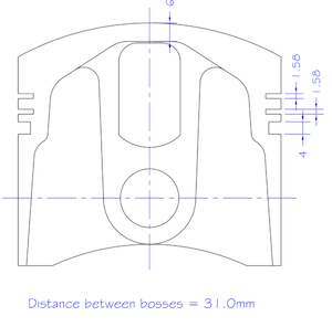
As the piston offers a higher compression over standard, I will be making some conversion shims to lower this for owners that want to run the standard ignition & carburation.
The new bore size will be 85.51mm, and the capacity will now be 861 cc, but if you want to play with different combinations, I created an engine size calculator here
Panhard pistons - order placed
Saturday 24 March 2012 Filed in: Panhard Piston
Over the last week, I managed to speak to the piston people, and what an engaging process that was. I started with a set idea in my head, and I really thought I knew what I wanted and then due to the limitations of the top ring to sleeve distance, the high compression or deck height of the standard set and the need for simplicity in installation, I had to go a different route.
As I discussed earlier, you can make anything work, but I wanted to avoid this. Pistons can be made in three ways, casting, forging and CNC from solid, but there are cost and number implications along the way. There are insufficient numbers to make a casting, and CNC from solid is double the expense of a machined forging, because it spends more time in the CNC machine, and has higher CAD/CAM costs. So that leaves forging and machining as the most suitable choice, but only if you can use an existing forging.
Panhard engines belong to an older generation of engine design, because nowadays you look to minimise surface areas in pistons and combustion chambers, which means domed pistons and hemispherical chambers are out. The implications for the forgings blanks are that most modern engine pistons do not have the large compression heights, and the top ring to compression height is minimised to reduce detonation, so the forgings are too small. The other thing is the bore size is slightly unusual, so you are generally looking at imperial forgings if you want to reuse the same liners.
The closest possible match to the Panhard piston on paper is a Royal Enfield Bullet piston, and that is what I thought I would be using, but it wasn’t after talking to the piston guru. I knew it was too heavy at over 600g complete, and so didn’t meet the weight targets, but I thought a little tweak here and there would sort that. It turns out it is unsuitable with the Panhard liner, and although it is good enough for a Royal Enfield, it isn’t for us.
It turns out when you look for a suitable forging, you look at the inside not the outside first, because if you want an intrinsically good design and therefore light as possible, the inner forging profile must match or follow the outer profile requirements closely, and believe it or not the original cast Panhard piston does this already. Now the selection is starting to get more focussed, so all that is really needed is a suitable forging with a domed inner profile, and enough room for the top ring detail. At this point I had to leave the meeting, because the piston designer had to look at the forging blanks in the old store. When I got back, it was really fortunate the company has been in business for 40 years, and had saved examples of the 320 forgings tools they had stored, because he found several pistons he thought might be suitable.
A short discussion later, and the choices were reduced to just one, and I just needed to confirm the dimensions in an email, so that production could be started. When I got home I burretted the combustion chamber and subtracted the piston dome volume, and worked backwards to get a higher compression version. This can always be reduced by shimming, like the original system, however I’ll be using new laser cut shims to vary the compression ratio. The 2012 engine will have a higher compression ratio, to make the more modern ring design work effectively. The latter is the limiting factor for the final rebore dimension, as it will be an existing imperial oversize set that I’ll be using. Incidentally, the oil supply for the piston pin will come off the liner walls and lubricate the piston pin via the oil control ring drillings.
As it is the start of the race season there is now a 12 week lead time, instead of the listed 8 weeks, and so today I placed an order for 12 pistons, which is six sets. This is a special developmental batch and it has a one off early adopter price, but the next batch will cost more at around £350 a set. There will need to be a piston pin or gudgeon pin conversion bush made to fit the standard rod, which varies anyway depending on the engine, that will add a little more cost to the total required. Any standard cylinder liners can be reused as they are over bored to a new controlled size. The pistons are expected to be available around the 18 June 2012. More details and pictures to be added later, but the piston is similar to this, without the valve pockets and with a smaller pin diameter.
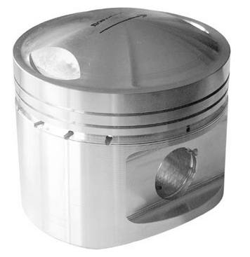
There is no doubt in my mind, over the next few batches a truly modern Panhard piston will be developed. One of the most important elements for me, is the company will continually refine the design when they receive used examples by modifying the machining incrementally. This will reduce the wear characteristics, and allows for smaller piston to cylinder liner clearances to be used and also maintain the correct clearances when hot, which brings further improvements, but the piston becomes tailored to the engine combustion processes.
This fits in with my philosophy of creating a remanufactured standard engine, that incorporates modern thinking, increases reliability, and as an added bonus, additional performance improvement too. As this work involves an engine rebuild, it would be foolish not to incorporate the other benefits I have found over the years, and this fits well with a staged development program.
Obviously this depends on what the car is being used for and/or the individual views of the owner, and it’s basically a debate about keeping original no matter what, or improving on originality, so that it can be used today. Whatever your views, or standpoint the Panhard engine is not reliable by modern day standards, and is a ticking time bomb if you own one without knowing its’ condition. For people that use their cars, you must as a general rule, no matter what side of the fence you sit...
1. Improve the oil capacity and filtration, and protect what you have.
2. Look at the crankshaft sometime, preferably rebuild it using the Peter Breed system, but definitely reduce the original crankshaft loadings by fitting lightweight pistons.
3. If you fit lightweight pistons, you should get the cylinder induction ported to reduce reversion, which counteracts the original fuelling variations and makes for smoother everyday running. I would also recommend an annealed copper gasket at the inlet manifold joint aka Peter Breed.
4. Improve the ignition timing, by fitting a modern full electronic ignition system and twin plug the head. This will improve starting, the main ignition events, and reduce the likelihood of marginal combustion triggering pinking, detonation or worst case holed pistons.
It is no coincidence that I am developing products to fit these stages, and the pistons are first to be announced as they have the longest lead time. All will be seen on the 2012 engine, which although it will look like a standard engine to most eyes, it will be totally re-engineered under the skin for use in modern day traffic (including the annual bash around Monthléry).
As I discussed earlier, you can make anything work, but I wanted to avoid this. Pistons can be made in three ways, casting, forging and CNC from solid, but there are cost and number implications along the way. There are insufficient numbers to make a casting, and CNC from solid is double the expense of a machined forging, because it spends more time in the CNC machine, and has higher CAD/CAM costs. So that leaves forging and machining as the most suitable choice, but only if you can use an existing forging.
Panhard engines belong to an older generation of engine design, because nowadays you look to minimise surface areas in pistons and combustion chambers, which means domed pistons and hemispherical chambers are out. The implications for the forgings blanks are that most modern engine pistons do not have the large compression heights, and the top ring to compression height is minimised to reduce detonation, so the forgings are too small. The other thing is the bore size is slightly unusual, so you are generally looking at imperial forgings if you want to reuse the same liners.
The closest possible match to the Panhard piston on paper is a Royal Enfield Bullet piston, and that is what I thought I would be using, but it wasn’t after talking to the piston guru. I knew it was too heavy at over 600g complete, and so didn’t meet the weight targets, but I thought a little tweak here and there would sort that. It turns out it is unsuitable with the Panhard liner, and although it is good enough for a Royal Enfield, it isn’t for us.
It turns out when you look for a suitable forging, you look at the inside not the outside first, because if you want an intrinsically good design and therefore light as possible, the inner forging profile must match or follow the outer profile requirements closely, and believe it or not the original cast Panhard piston does this already. Now the selection is starting to get more focussed, so all that is really needed is a suitable forging with a domed inner profile, and enough room for the top ring detail. At this point I had to leave the meeting, because the piston designer had to look at the forging blanks in the old store. When I got back, it was really fortunate the company has been in business for 40 years, and had saved examples of the 320 forgings tools they had stored, because he found several pistons he thought might be suitable.
A short discussion later, and the choices were reduced to just one, and I just needed to confirm the dimensions in an email, so that production could be started. When I got home I burretted the combustion chamber and subtracted the piston dome volume, and worked backwards to get a higher compression version. This can always be reduced by shimming, like the original system, however I’ll be using new laser cut shims to vary the compression ratio. The 2012 engine will have a higher compression ratio, to make the more modern ring design work effectively. The latter is the limiting factor for the final rebore dimension, as it will be an existing imperial oversize set that I’ll be using. Incidentally, the oil supply for the piston pin will come off the liner walls and lubricate the piston pin via the oil control ring drillings.
As it is the start of the race season there is now a 12 week lead time, instead of the listed 8 weeks, and so today I placed an order for 12 pistons, which is six sets. This is a special developmental batch and it has a one off early adopter price, but the next batch will cost more at around £350 a set. There will need to be a piston pin or gudgeon pin conversion bush made to fit the standard rod, which varies anyway depending on the engine, that will add a little more cost to the total required. Any standard cylinder liners can be reused as they are over bored to a new controlled size. The pistons are expected to be available around the 18 June 2012. More details and pictures to be added later, but the piston is similar to this, without the valve pockets and with a smaller pin diameter.
There is no doubt in my mind, over the next few batches a truly modern Panhard piston will be developed. One of the most important elements for me, is the company will continually refine the design when they receive used examples by modifying the machining incrementally. This will reduce the wear characteristics, and allows for smaller piston to cylinder liner clearances to be used and also maintain the correct clearances when hot, which brings further improvements, but the piston becomes tailored to the engine combustion processes.
This fits in with my philosophy of creating a remanufactured standard engine, that incorporates modern thinking, increases reliability, and as an added bonus, additional performance improvement too. As this work involves an engine rebuild, it would be foolish not to incorporate the other benefits I have found over the years, and this fits well with a staged development program.
Obviously this depends on what the car is being used for and/or the individual views of the owner, and it’s basically a debate about keeping original no matter what, or improving on originality, so that it can be used today. Whatever your views, or standpoint the Panhard engine is not reliable by modern day standards, and is a ticking time bomb if you own one without knowing its’ condition. For people that use their cars, you must as a general rule, no matter what side of the fence you sit...
1. Improve the oil capacity and filtration, and protect what you have.
2. Look at the crankshaft sometime, preferably rebuild it using the Peter Breed system, but definitely reduce the original crankshaft loadings by fitting lightweight pistons.
3. If you fit lightweight pistons, you should get the cylinder induction ported to reduce reversion, which counteracts the original fuelling variations and makes for smoother everyday running. I would also recommend an annealed copper gasket at the inlet manifold joint aka Peter Breed.
4. Improve the ignition timing, by fitting a modern full electronic ignition system and twin plug the head. This will improve starting, the main ignition events, and reduce the likelihood of marginal combustion triggering pinking, detonation or worst case holed pistons.
It is no coincidence that I am developing products to fit these stages, and the pistons are first to be announced as they have the longest lead time. All will be seen on the 2012 engine, which although it will look like a standard engine to most eyes, it will be totally re-engineered under the skin for use in modern day traffic (including the annual bash around Monthléry).
Panhard pistons - a quick overview
Sunday 11 March 2012 Filed in: Panhard Piston
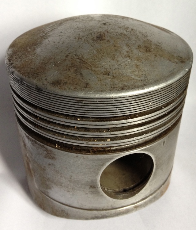
Panhard pistons are quite heavy and bulky items compared to their modern day equivalents, because the piston has to be domed to make the compression high enough within the hemispherical combustion chamber in the Panhard engine.
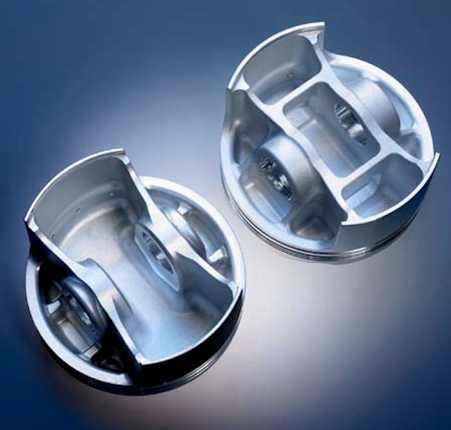
The biggest limiting factor is the close proximity of the top ring to the end of the steel liner, and because the top ring is quite far down the piston, around 10mm from the top deck, this really limits what pistons you can use. BMW R80 non Nicasil, circa 1980’s, can be used, but they are very scarce, as most people fit the 1000cc conversion kits, as they are cheaper. You can also get a piston from Peter Breed, which is a forged American item. Others that can be used are various Italian, German, American & British designs, but nearly all require a little rework to the cylinders to overcome the cylinder liner problem.
What do the standard pistons look like? Here’s the troublesome liner position, and it’s about 1.5mm from the top ring…this pic is taken from a cutaway section.
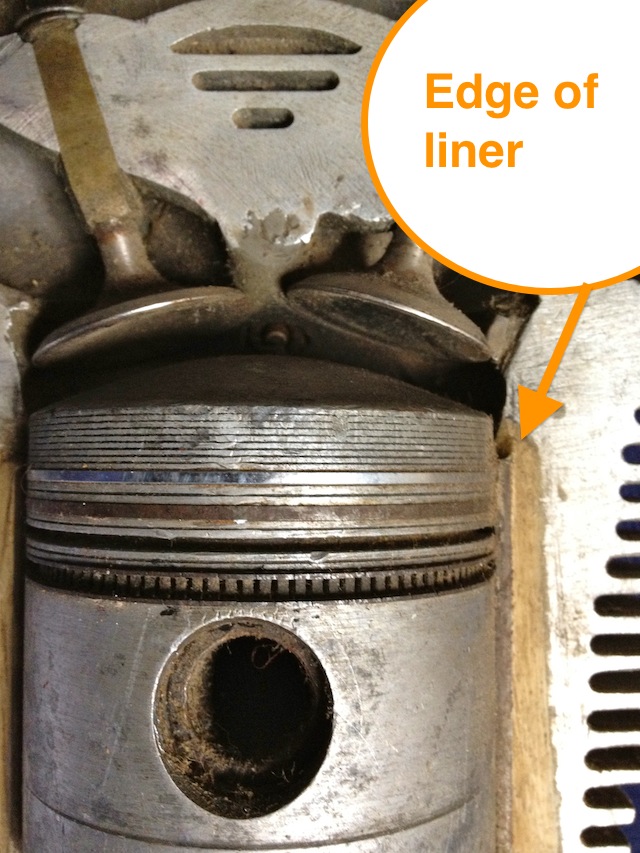
These engines were from the junk pile, but they still have their uses, as the piston below was cut up to show the typical cross-sectional areas that exist within the original. There are more than one type of Panhard piston used in the flat twin engine, but this is the later 4 ringed type.
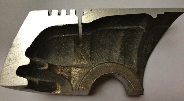
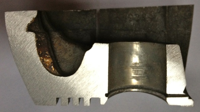
Why is this done? I need to understand why the naked Panhard piston weighs 505 grams, when my achievable target weight for a heavily domed piston should be sub 400grams, which for example is double the weight of a single cylinder Supermotard piston from 2002, and probably three times heavier than a complete MotoGP piston! However, pistons that light do have very short maintenance cycles, which are measured in hours not years.
Panhard crankcase rear bearing support
Saturday 10 March 2012 Filed in: Panhard Oil
I was going to remove the rear NU209 main bearing on the engine, but needed to make a small adaptor to measure the end float on the crankshaft before I do so. This particular engine has a little bit of movement in the rear crank pin, and I need to find out why it has moved.
Historically the engines have had gradual tweaks over their lifetime, and the rear main bearing support plate which bolts to the crankcase is no exception. The first ones were aluminium, and the later ones were cast iron with a flexible lipped seal, as opposed to a steel piston ring. Oil starvation and inadequate capacity have always been an issue, as the cars were introduced to the ever increasing demands of modern day traffic, and I spotted another tweak today.
The early M6 back plate is on the left and the later M8 is on the right, and can you spot the difference?
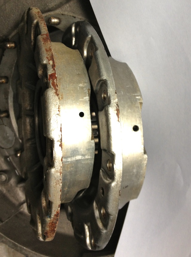
The answer is the holes are bigger on the later one, which means more oil can be supplied to the rear bearing. After measuring these it equates to an improvement of 15% over the earlier design.
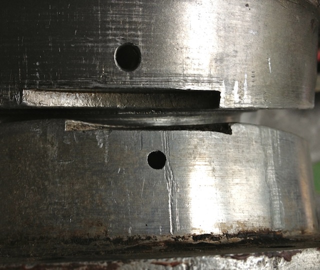
Historically the engines have had gradual tweaks over their lifetime, and the rear main bearing support plate which bolts to the crankcase is no exception. The first ones were aluminium, and the later ones were cast iron with a flexible lipped seal, as opposed to a steel piston ring. Oil starvation and inadequate capacity have always been an issue, as the cars were introduced to the ever increasing demands of modern day traffic, and I spotted another tweak today.
The early M6 back plate is on the left and the later M8 is on the right, and can you spot the difference?
The answer is the holes are bigger on the later one, which means more oil can be supplied to the rear bearing. After measuring these it equates to an improvement of 15% over the earlier design.
Panhard crankcase front oil drilling modifications
Sunday 04 March 2012 Filed in: Panhard Oil
The original engines had this oil feed visible above the camshaft bore at the very front of the crankcase, which is shown below. As the camshaft rotates this drilling is filled two times per camshaft revolution, and after this it passes in a trough that is underneath the bearing and the oil jumps into the slingers. Some oil splashes back and passes through the main bearing, but the rest is accelerated by the slingers at the crank web, and passes through the big end bearing via a drilling in the crank web before exiting and splash lubricating the little end.
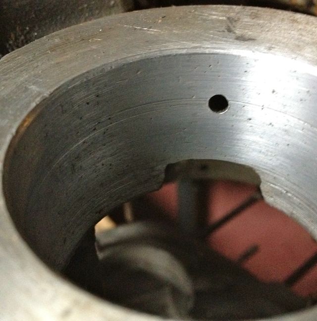
Unfortunately this hole is too small, and it is the cause of a 50% reduction in flow rate over the rear pro rata. There is an added complication that this hole is also 50% smaller than the rear oil feed, so there is quite a bit of reduction in potential flow rate assuming the pressures were the same. As you might have read there is a pressure difference, because of the secondary drilling that fed the camshaft timing gear on the early engines which compounded the problem , and led to reliability issues, which eventually forced an engine redesign to this area.
This can be negated by carrying out a few modifications, all of which will be documented here.
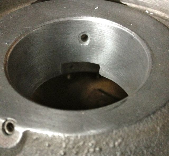
It might not be obviously apparent from this picture, but the hole size is now 6mm diameter, whereas the one above is just 4mm. This new oil feed now matches the camshaft aperture, so all openings, front and rear are timed equally. The 4mm diameter hole in the middle that is drilled presently, will have to be enlarged to 5mm to match the rear oil feed that is fed from the common camshaft oil gallery. At first it is more important to get the hole in the right position, and work from this, which is why it is now at 5mm diameter, as shown below.
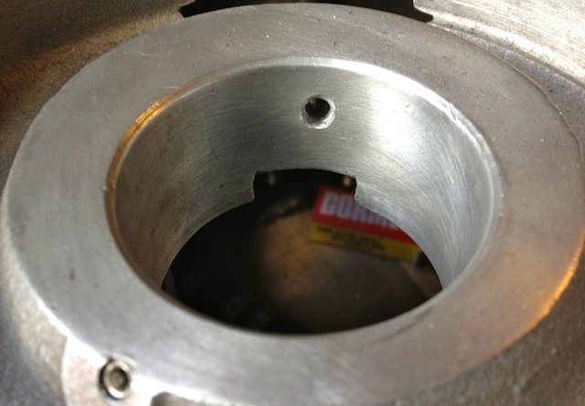
This now means both front and rear oil galleries are equally phased and have the same pressure variations, as there is no mismatched timing gear oil feed anymore affecting the front oil supply. However that still leaves the task of creating a new oil feed to do this, because you didn’t think the gear was going to lubricate itself from the plain bearing leaking, but that’ll be another update.
Unfortunately this hole is too small, and it is the cause of a 50% reduction in flow rate over the rear pro rata. There is an added complication that this hole is also 50% smaller than the rear oil feed, so there is quite a bit of reduction in potential flow rate assuming the pressures were the same. As you might have read there is a pressure difference, because of the secondary drilling that fed the camshaft timing gear on the early engines which compounded the problem , and led to reliability issues, which eventually forced an engine redesign to this area.
This can be negated by carrying out a few modifications, all of which will be documented here.
It might not be obviously apparent from this picture, but the hole size is now 6mm diameter, whereas the one above is just 4mm. This new oil feed now matches the camshaft aperture, so all openings, front and rear are timed equally. The 4mm diameter hole in the middle that is drilled presently, will have to be enlarged to 5mm to match the rear oil feed that is fed from the common camshaft oil gallery. At first it is more important to get the hole in the right position, and work from this, which is why it is now at 5mm diameter, as shown below.
This now means both front and rear oil galleries are equally phased and have the same pressure variations, as there is no mismatched timing gear oil feed anymore affecting the front oil supply. However that still leaves the task of creating a new oil feed to do this, because you didn’t think the gear was going to lubricate itself from the plain bearing leaking, but that’ll be another update.
Panhard crankcase camshaft drive gear oil level
Sunday 04 March 2012 Filed in: Panhard Oil
A little mod that improves oil quality, reduces heat build up in the oil, and improves pumping losses to the engine. At the moment the Panhard timing case oil level is determined by the hi level drainage points shown here or leaking past the front main bearing.
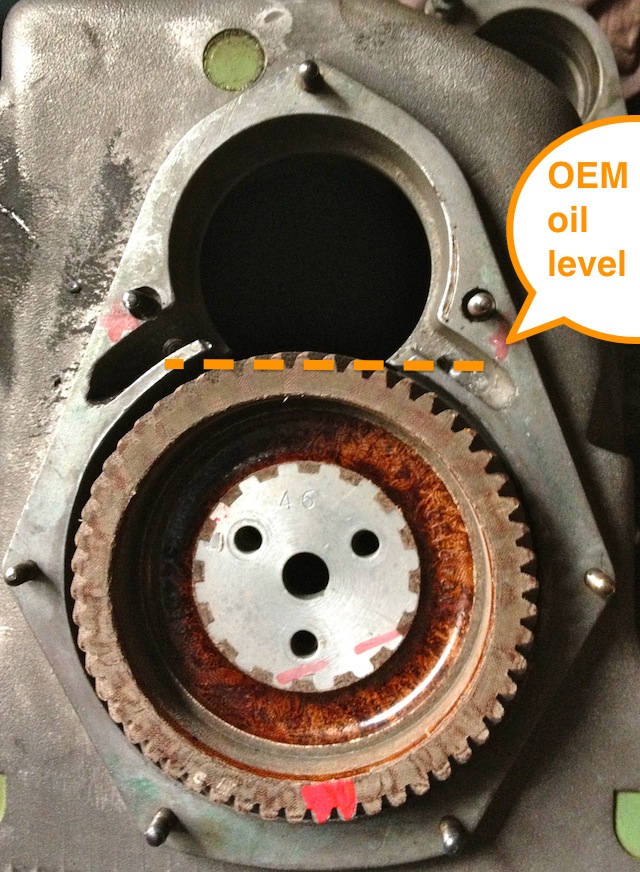
Normal practice for a splash lubricated gear is to have no more than a third of the overall gear diameter immersed, so why Panhard did this surprises me. Originally they had a fibre wheel of massive proportions meshing to a hardened steel gear, with huge gear area, and in all fairness it probably didn’t need much lubrication. If it was being made today this fibre wheel, which is often replaced by an aluminium one, could be made of a plastic material quite easily.
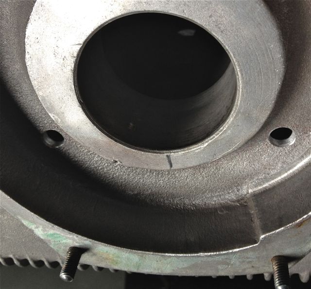
These new drillings, now restore the status quo, and at the same time allow for this area to get some oil changes. Technically these wouldn’t get fully drained, unless you remove the steel timing cover case, because there is no low level return point. I think it is realistic to revise this mod and lower the oil level further, but as this is the third engine I have modded in this area, I will wait until I get some better feedback before doing so.
Normal practice for a splash lubricated gear is to have no more than a third of the overall gear diameter immersed, so why Panhard did this surprises me. Originally they had a fibre wheel of massive proportions meshing to a hardened steel gear, with huge gear area, and in all fairness it probably didn’t need much lubrication. If it was being made today this fibre wheel, which is often replaced by an aluminium one, could be made of a plastic material quite easily.
These new drillings, now restore the status quo, and at the same time allow for this area to get some oil changes. Technically these wouldn’t get fully drained, unless you remove the steel timing cover case, because there is no low level return point. I think it is realistic to revise this mod and lower the oil level further, but as this is the third engine I have modded in this area, I will wait until I get some better feedback before doing so.
Panhard oil pump output
Sunday 04 March 2012 Filed in: Panhard Oil
I have mentioned earlier that the Panhard oil supply was designed to be a low flow, low oil pressure system, but I haven’t really explained why.
Originally the engine had a lot of roller bearings inside it, and crucially the crankshaft was suspended using these. In fact cylindrical roller bearing set ups are making a come back in engine design, especially in the USA where Timken are applying this to some current engines, to showcase the technology again, and also promote their own bearing interests. One of the reasons they are using it, is to reduce pumping losses, and the frictional drag reductions against the more common plain bearing engines, because there is an environmental need to make combustion engines more economical.
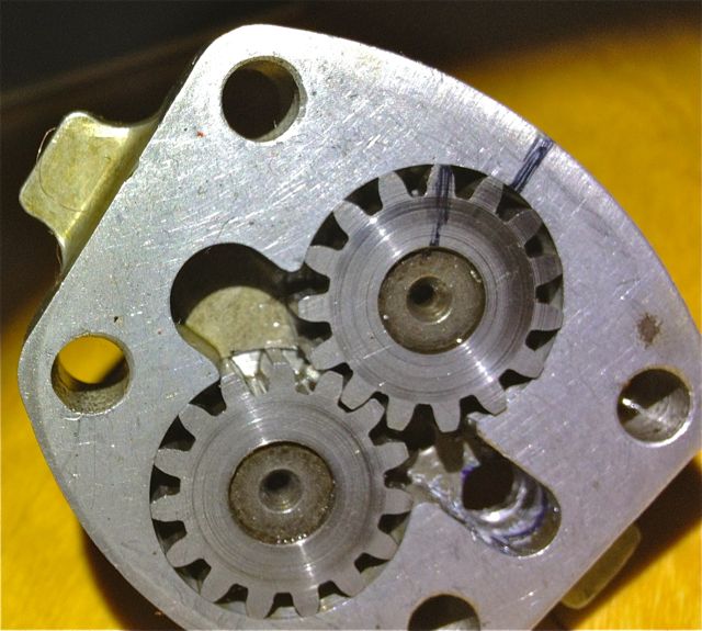
The Panhard engine was quite clever in that it used a small pump to get the oil roughly where it was needed, and then the centrifugal effect of the slingers in the crankshaft webs gave a speed related response to the engine needs. This was a good fit with the requirements of the engine, and although there was a maintenance issue with slingers clogging up, mileages were not great in the late 1940’s when the engine was being designed, and a 30,000 mile target wasn’t unreasonable. Fast forward to the 21st Century and maybe some things would be different now, and if you look at the evolution of a similar engine, the BMW R50 motorcycle, that moved from centrifugal oil supply to a cross drilled crank, and the more common one piece crankshaft & split connecting rods with plain bearings.
Aside from the maintenance issue with the slingers, there is nothing really wrong with the original oil pump, but if you read the history books you might be lead to believe otherwise. Here is the pump, and it is a gear type oil pump, which was a current design around the time, and it is more than adequate for the job. There are a couple of issues, that if it was being made today, that you would change, but I’ll elaborate later.The first one is, there are no rounded edges from the oil pump body into the output drilling, which is 90 degrees to it, and this will cause back pressure and cavitation, at higher oil volumes .
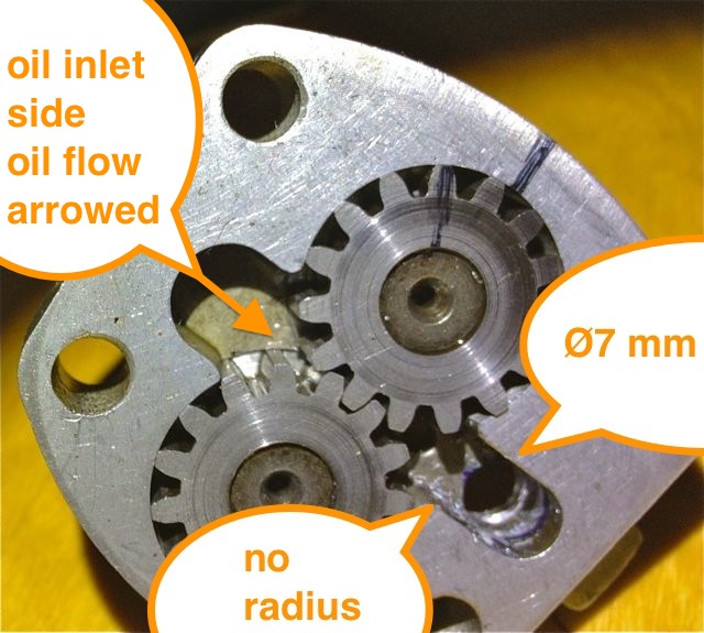
So if I was going to do one thing to address this, it would involve using a Dremel and doing this.
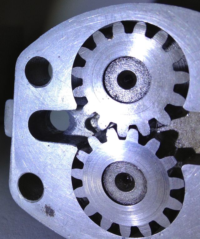
This modified oil pump will now flow more oil at speed, when you want it and there will be less bubbles in the oil as a result, which has the effect of improving the oil quality. I have successfully done this on three engines to date, and did test it out on the oil filter crankcase test rig many years ago. It is beneficial, and is one way of simply boosting the nett oil flow, but there is a bigger win win at the crankcase entry. If you were trying to maximise flow, you wouldn’t squeeze a garden hose pipe, but that’s exactly what Panhard did, because the crankcase oil inlet from the pump is 4.8mm diameter, yet the pump output is 7mm in diameter, which is almost a 50% reduction in cross sectional area. So after radiussing the outlet of the pump body there is an even bigger restriction downstream, and all the oil for the engine is fed by this small hole. It really doesn’t make sense with hindsight
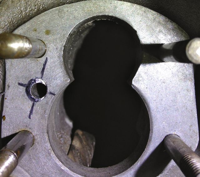
You can see the small inlet pipe into the crankcase, and also see where the oil pump mates up to it, which is the black circle I have inked in and the centre of the outlet is represented by the black lines. So again the flexible shaft is used to reshape this area, and the important thing is to match the mating diameters more closely. It makes sense to machine and open up this drilling to match the oil pump, as this will increase the flow rate into the main oil galleries, and it has no effect on the pressure of the system, contrary to what you might think. The pressure in the unmodified camshaft is controlled by the cross drilling after this, and the cylinder head feeds likewise by the size of their respective openings too.
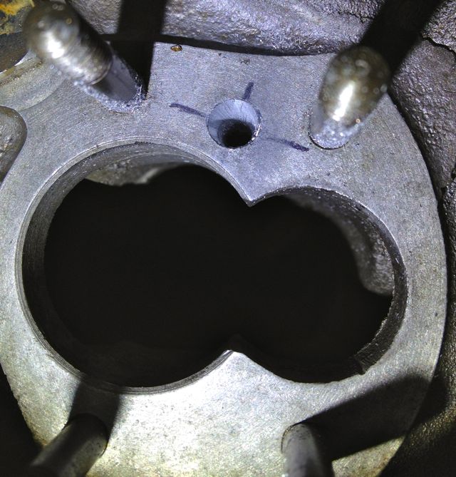
Crankcase main oil gallery modified to match oil pump outlet diameter.
Originally the engine had a lot of roller bearings inside it, and crucially the crankshaft was suspended using these. In fact cylindrical roller bearing set ups are making a come back in engine design, especially in the USA where Timken are applying this to some current engines, to showcase the technology again, and also promote their own bearing interests. One of the reasons they are using it, is to reduce pumping losses, and the frictional drag reductions against the more common plain bearing engines, because there is an environmental need to make combustion engines more economical.
The Panhard engine was quite clever in that it used a small pump to get the oil roughly where it was needed, and then the centrifugal effect of the slingers in the crankshaft webs gave a speed related response to the engine needs. This was a good fit with the requirements of the engine, and although there was a maintenance issue with slingers clogging up, mileages were not great in the late 1940’s when the engine was being designed, and a 30,000 mile target wasn’t unreasonable. Fast forward to the 21st Century and maybe some things would be different now, and if you look at the evolution of a similar engine, the BMW R50 motorcycle, that moved from centrifugal oil supply to a cross drilled crank, and the more common one piece crankshaft & split connecting rods with plain bearings.
Aside from the maintenance issue with the slingers, there is nothing really wrong with the original oil pump, but if you read the history books you might be lead to believe otherwise. Here is the pump, and it is a gear type oil pump, which was a current design around the time, and it is more than adequate for the job. There are a couple of issues, that if it was being made today, that you would change, but I’ll elaborate later.The first one is, there are no rounded edges from the oil pump body into the output drilling, which is 90 degrees to it, and this will cause back pressure and cavitation, at higher oil volumes .
So if I was going to do one thing to address this, it would involve using a Dremel and doing this.
This modified oil pump will now flow more oil at speed, when you want it and there will be less bubbles in the oil as a result, which has the effect of improving the oil quality. I have successfully done this on three engines to date, and did test it out on the oil filter crankcase test rig many years ago. It is beneficial, and is one way of simply boosting the nett oil flow, but there is a bigger win win at the crankcase entry. If you were trying to maximise flow, you wouldn’t squeeze a garden hose pipe, but that’s exactly what Panhard did, because the crankcase oil inlet from the pump is 4.8mm diameter, yet the pump output is 7mm in diameter, which is almost a 50% reduction in cross sectional area. So after radiussing the outlet of the pump body there is an even bigger restriction downstream, and all the oil for the engine is fed by this small hole. It really doesn’t make sense with hindsight
You can see the small inlet pipe into the crankcase, and also see where the oil pump mates up to it, which is the black circle I have inked in and the centre of the outlet is represented by the black lines. So again the flexible shaft is used to reshape this area, and the important thing is to match the mating diameters more closely. It makes sense to machine and open up this drilling to match the oil pump, as this will increase the flow rate into the main oil galleries, and it has no effect on the pressure of the system, contrary to what you might think. The pressure in the unmodified camshaft is controlled by the cross drilling after this, and the cylinder head feeds likewise by the size of their respective openings too.
Crankcase main oil gallery modified to match oil pump outlet diameter.
Panhard crankcase oil circulation modifications (revisited)
Saturday 03 March 2012 Filed in: Panhard Oil
A quick history lesson on Panhard engine failures. The front main bearing and front cylinder crankshaft big end started to develop failures, as they increased the horsepower. It was attributed to insufficient oil supply, and so the front end lubrication was revised, and the camshaft timing gears were used as a splash lubrication system and the oil drilling that provided that role under the front main bearing was removed. This modification was introduced from around the early 1960’s, and ran to the end of production in 1967.
Unfortunately for Panhard they were barking up the wrong tree, despite the engine coming from a well thought out design originally, other people tinkered with the design knee jerk fashion as the problems developed, and nobody took an overview and look at the root causes. The financial woes and Citröen management probably didn’t help, but as Panhard died in 1967, we will never really know.
Flash forward to the next century, and if you are running one of these engines, it will almost be suffering from the result of this modification. As the engine ages the oil pump becomes more marginal, the priority oil fed valve gear bushes in the head wear, and the oil into the camshaft gallery reduces. Now the front bearings don’t really fatigue like they used to, but the rears suffer because they are pump related. So the problem has transferred itself, and the question that should be asked is why?
Of course if you look at the development of these engines you will read about the engines modified for endurance racing, which had higher capacity pumps, and an increased oil capacity with the fitment of an additional sump, that also acted as a baffled cavity for the oil pick up pipe. This subset of development has been an evolutionary branch of Panhard engine that needs revising, because if you really look at the problem, these solutions are papering over the cracks of a design fault. If you go back in time, and look at the engine design of the Panhard flat twin compared to others, there are numerous good points taken from lots of influences. The crankshaft oil supply is reminiscent of Bugatti & the early BMW motorcycle engines, but it is essentially a low pressure system, and even the design of the original plain bearing surfaces reflect this, so why fit a higher pressure set up, but that’s another story.
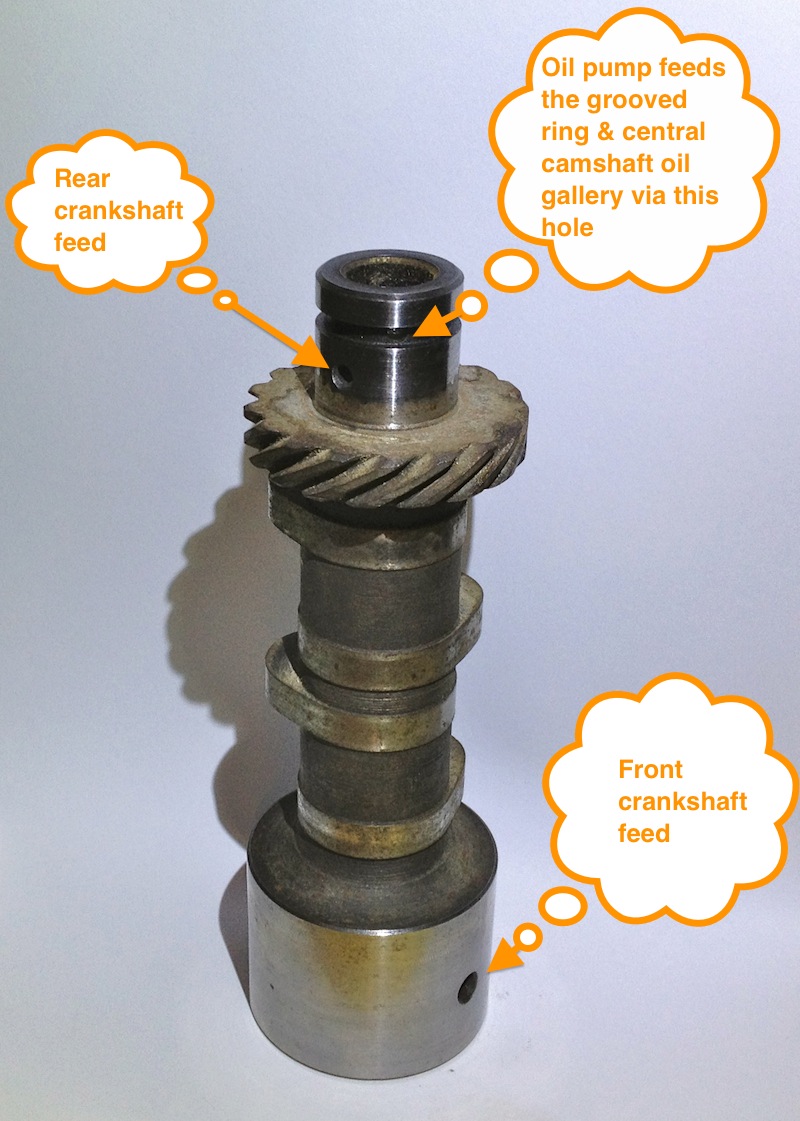
For example in the front bearing of the camshaft, which has a very large diameter at the front where the timing gear is driven by the crankshaft, and a more normal sized bearing diameter at the rear. Also, if you look at the oil drillings that feed these plain bearings, they are proportionately scaled to suit. The camshaft is the common denominator in all of this because it is one of three main oil feeds from the oil pump, and the supply conduit for the front and rear main bearings and the crankshaft lubrication, but wasn’t there a problem here?
So how can a central oil gallery that feeds both the front and rear crankshafts be at fault? Actually, the central gallery is not the problem, because the flow into this is separate from the outputs, and if you look at these, the problem is almost explained. The original designer knew he needed to equalise the distribution of the oil, so the oil outputs for the front and rear crankshaft feeds are phased to do just this, and as the cross drillings are on a rotating surface the timing window on the camshafts are scaled accordingly. However, although the rear crankshaft oil drilling is sized to match the rear camshaft drilling, the front is mismatched, because the oil drilling in the crankcase is too small.
On examination the oil drilling needs to be around 6mm diameter, when it is only 4mm, which is a 50% reduction in oil supply compared to the rear, and this alone would explain the front end failure susceptibility, but it doesn’t end there. The original designer tried to phase the oil supply to the front and rear ends equally, but somebody else decided the camshaft timing gear at the front should have some more lubrication, and put in an additional drilling. The reality was that the original plain bearing would have leaked into this cavity, and as there were no low level drainage holes, the oil wouldn’t go away, so it really didn’t need the additional drilling, but the biggest problem was where it was positioned. The oil pump doesn’t need to be big, as the engine only needed low flow rates and low pressure to work within it original design specifications, however any pressure drop say after a drilling would take a little time to recover, and this was accepted in the design layout, but as soon as the oil drilling to the front timing gear was placed ahead of the front end oil supply, the 50% reduction in flow rate all things being equal just got worse, as this drilling lost pressure after 60 degrees of a 90 degree recovery window, and only gave the camshaft 30 degrees to recover the oil pressure in the gallery. This means the front crankshaft oil feeds are compromised further, whereas the rears are unaffected, and it was all down to a simple production oversight.
What is the solution? Again, a quick history lesson will tell you all you need to know, and it is the route of many flat twin Panhard devotees, but don’t bother looking at the history books, what you have to do is engine specific, but that’ll be for another day. Suffice to say, I spotted this many years ago, and have been making parts and modding a few engines to overcome these oil related faults every time I get hold of one.
A quick walkthrough of what to do
1. Mod the oil pump
2. Mod the crankcase oil circuits, two different methods for the M6 & M10 engines.
3. Make a new oil light piston or buy one from me
1. Modify the oil pump
Originally the engine had a lot of roller bearings inside it, and crucially the crankshaft was suspended using these. In fact cylindrical roller bearing set ups are making a come back in engine design, especially in the USA where Timken are applying this to some current engines, to showcase the technology again, and also promote their own bearing interests. One of the reasons they are using it, is to reduce pumping losses, and the frictional drag reductions against the more common plain bearing engines, because there is an environmental need to make combustion engines more economical.
The Panhard engine was quite clever in that it used a small pump to get the oil roughly where it was needed, and then the centrifugal effect of the slingers in the crankshaft webs gave a speed related response to the engine needs. This was a good fit with the requirements of the engine, and although there was a maintenance issue with slingers clogging up, mileages were not great in the late 1940’s when the engine was being designed, and a 30,000 mile target wasn’t unreasonable. Fast forward to the 21st Century and maybe some things would be different now, and if you look at the evolution of a similar engine, the BMW R50 motorcycle, that moved from centrifugal oil supply to a cross drilled crank, and the more common one piece crankshaft & split connecting rods with plain bearings.
Aside from the maintenance issue with the slingers, there is nothing really wrong with the original oil pump, but if you read the history books you might be lead to believe otherwise. Here is the pump, and it is a gear type oil pump, which was a current design around the time, and it is more than adequate for the job. There are a couple of issues, that if it was being made today, that you would change, but I’ll elaborate later.The first one is, there are no rounded edges from the oil pump body into the output drilling, which is 90 degrees to it, and this will cause back pressure and cavitation, at higher oil volumes .
So if I was going to do one thing to address this, it would involve using a Dremel and doing this.
This modified oil pump will now flow more oil at speed, when you want it and there will be less bubbles in the oil as a result, which has the effect of improving the oil quality. I have successfully done this on three engines to date, and did test it out on the oil filter crankcase test rig many years ago. It is beneficial, and is one way of simply boosting the nett oil flow, but there is a bigger win win at the crankcase entry. If you were trying to maximise flow, you wouldn’t squeeze a garden hose pipe, but that’s exactly what Panhard did, because the crankcase oil inlet from the pump is 4.8mm diameter, yet the pump output is 7mm in diameter, which is almost a 50% reduction in cross sectional area. So after radiussing the outlet of the pump body there is an even bigger restriction downstream, and all the oil for the engine is fed by this small hole. It really doesn’t make sense with hindsight
You can see the small inlet pipe into the crankcase, and also see where the oil pump mates up to it, which is the black circle I have inked in and the centre of the outlet is represented by the black lines. So again the flexible shaft is used to reshape this area, and the important thing is to match the mating diameters more closely. It makes sense to machine and open up this drilling to match the oil pump, as this will increase the flow rate into the main oil galleries, and it has no effect on the pressure of the system, contrary to what you might think. The pressure in the unmodified camshaft is controlled by the cross drilling after this, and the cylinder head feeds likewise by the size of their respective openings too.
Crankcase main oil gallery modified to match oil pump outlet diameter.
2. Modify the crankcase (M10S version below)
This engine is the later type, so needs modifying back to the original oil supply route, but adding the improvements necessary to negate the other faults. The first area to tackle is the front end crankshaft oil supply, so plugging the newer oil drillings and creating a matched new one under the front main bearing housing. These will be fixed with Loctite once all the drilling has finished and the crankcase has been thoroughly cleaned.
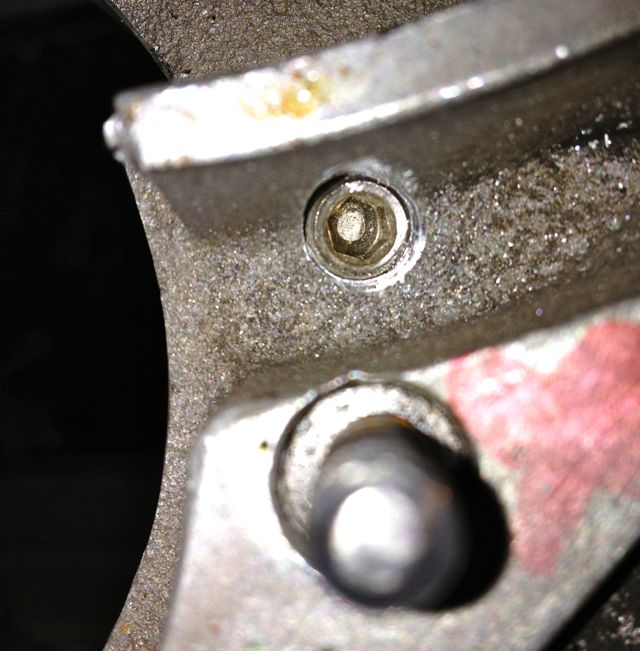
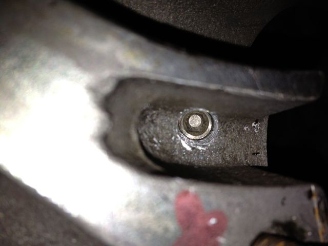
I will reduce the oil level & flow in the timing gear casing, so reduce pumping losses, and oil degradation. On examination the deposits in the slingers at the front part of the crankshaft were almost double those at the rear, which is mainly due to the oil supply being much greater to the front and also the timing gear casing is a stale oil residue trap. Once contaminated here, the particulates have no option but return via the main bearing aperture, and then be centrifuged in the front slinger and as there is no drain out of this area, the oil is never fully refreshed.
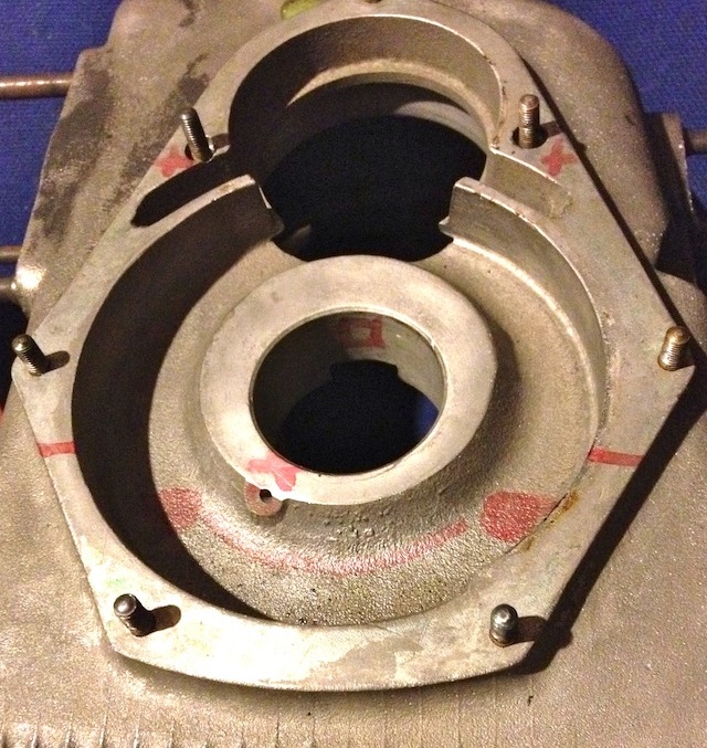
I have to modify the later style crankcase to adjust the oil circulation. This will mean creating a new big end feed under the front main bearing, plugging some of the existing galleries, and making new drain holes for the front timing gear. This will reduce pumping losses, lower oil temperatures and improve oil quality.
At the moment the Panhard timing case oil level is determined by the high level drainage points shown here or leaking past the front main bearing. In reality the OEM oil level never reaches this height, because the gears act like a huge waterwheel and churn through the bearing, but this still causes parasitic losses, and the modded race cars aka DBs, used a modified timing gear to overcome this.
Normal practice for a splash lubricated gear is to have no more than a third of the overall gear diameter immersed, so why Panhard did this surprises me. Originally they had a fibre wheel of massive proportions meshing to a hardened steel gear, with huge gear area, and in all fairness it probably didn’t need much lubrication. If it was being made today this fibre wheel, which is often replaced by an aluminium one, could be made of a plastic material quite easily.
These new drillings, now restore the status quo, and at the same time allow for this area to get some oil changes. Technically these wouldn’t get fully drained, unless you remove the steel timing cover case, because there is no low level return point. I think it is realistic to revise this mod and lower the oil level further, but as this is the third engine I have modded in this area, I will wait until I get some better feedback before doing so.
Now to mod the front crankshaft oil feed.
The later engines didn’t have this option, as can be seen here.

The original engines had this oil feed visible above the camshaft bore at the very front of the crankcase, which is shown below. As the camshaft rotates this drilling is filled two times per camshaft revolution, and after this it passes in a trough that is underneath the bearing and the oil jumps into the slingers. Some oil splashes back and passes through the main bearing, but the rest is accelerated by the slingers at the crank web, and passes through the big end bearing via a drilling in the crank web before exiting and splash lubricating the little end.
Unfortunately this hole is too small, and it is the cause of a 50% reduction in flow rate over the rear pro rata. There is an added complication that this hole is also 50% smaller than the rear oil feed, so there is quite a bit of reduction in potential flow rate assuming the pressures were the same. As you might have read there is a pressure difference, because of the secondary drilling that fed the camshaft timing gear on the early engines which compounded the problem , and led to reliability issues, which eventually forced an engine redesign to this area.
This can be negated by carrying out a few modifications, all of which will be documented here.
It might not be obviously apparent from this picture, but the hole size is now 6mm diameter, whereas the one above is just 4mm. This new oil feed now matches the camshaft aperture, so all openings, front and rear are timed equally. The 4mm diameter hole in the middle that is drilled presently, will have to be enlarged to 5mm to match the rear oil feed that is fed from the common camshaft oil gallery. At first it is more important to get the hole in the right position, and work from this, which is why it is now at 5mm diameter, as shown below.
Timing gear oil drilling plugged as shown below
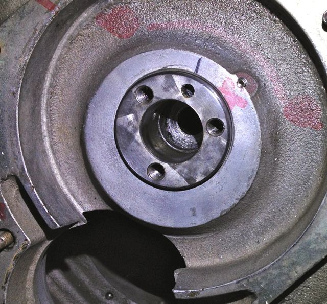
Plugging this drilling means both front and rear oil galleries are now equally phased and have the same pressure variations, as there is no mismatched timing gear oil feed anymore affecting the front oil supply. However that still leaves the task of creating a new oil feed to do this, because you didn’t think the gear was going to lubricate itself from the plain bearing leaking.
3. Make a new oil light piston or buy one from me!
To lubricate the camshaft gear I made some oil light pistons to replace the standard machined cast originals shown in the bottom picture.
This is the raw machined unit, it still needs a little more work. This new oil light piston has an integral relief valve built in, essentially, a ball spring and locking screw, and I set it at 2 bar or 30psi, but you can set this to whatever you want, and even increase the oil drilling if you want to make it larger.
The importance of this is that the original oil supply will now feed the cylinder heads and the hydraulic valve adjusters first as normal, then the front and rear bearings, and only then squirt oil into the timing gear when more pressure is reached. It also means that after the oil has fed the cylinder heads, the front and rear bearings get a much better oil supply.
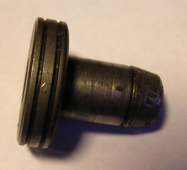
The original had a rounded tip, whereas mine had a threaded hole, which was part of the oil relief valve assembly, and I couldn’t really alter this unless I made a two part piston.
There was a concern that this nosing or tip, despite being rounded similar to the picture below …
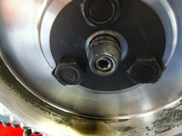
… would still abrade the oil light wooden button, and cause problems further down the line. In real usage it has no impact, but I did make a modified version for engine number 3 some years ago, which I believe isn’t necessary now.
So we have almost finished, just need to tweak the rear bearing oil supply...
Historically the engines have had gradual tweaks over their lifetime, and the rear main bearing support plate which bolts to the crankcase is no exception. The first ones were aluminium, and the later ones were cast iron with a flexible lipped seal, as opposed to a steel piston ring. Oil starvation and inadequate capacity have always been an issue, as the cars were introduced to the ever increasing demands of modern day traffic, and I spotted another tweak today.
The early M6 back plate is on the left and the later M8 is on the right, and can you spot the difference?
The answer is the holes are bigger on the later one, which means more oil can be supplied to the rear bearing. After measuring these it equates to an improvement of 15% over the earlier design.
This hole needs to be bigger to reduce the cavitation and back pressure, and also equalise the flow with the improved front bearing oil supply.

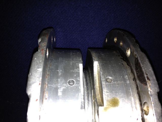
This is the left hand M6 casting after being modded at the inlet side, and the outlet must be modded too. Again the change of direction gets a smoothing radius on the inside corner.
.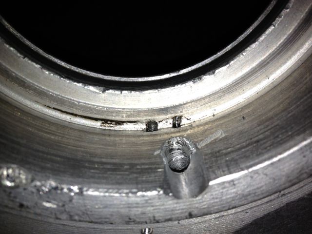
The hole has been smoothed and with a dummy bearing fitted you can see the difference in surface area, versus the older design underneath. What is not apparent is the hole is only 3mm in diameter just under the bearing on this M6 casting.
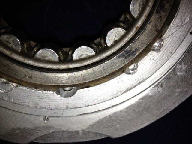
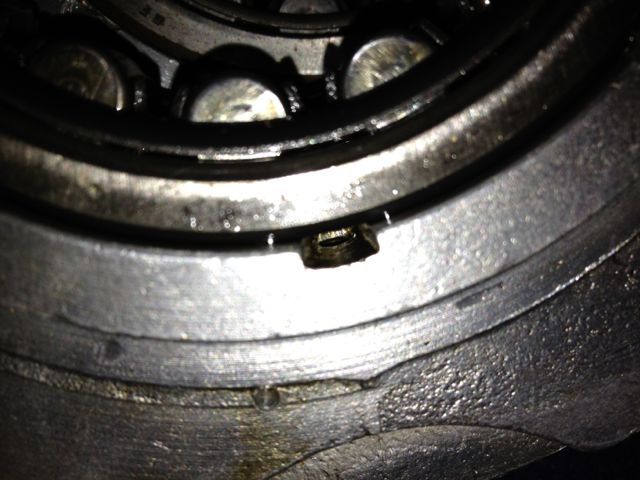
So that’s it. They are a few other tweaks that can be made, but modifying the oil circuits this way will improve a standard Panhard engine, and increase its reliability, especially if you dilter the oil and increase the sump capacity.
Unfortunately for Panhard they were barking up the wrong tree, despite the engine coming from a well thought out design originally, other people tinkered with the design knee jerk fashion as the problems developed, and nobody took an overview and look at the root causes. The financial woes and Citröen management probably didn’t help, but as Panhard died in 1967, we will never really know.
Flash forward to the next century, and if you are running one of these engines, it will almost be suffering from the result of this modification. As the engine ages the oil pump becomes more marginal, the priority oil fed valve gear bushes in the head wear, and the oil into the camshaft gallery reduces. Now the front bearings don’t really fatigue like they used to, but the rears suffer because they are pump related. So the problem has transferred itself, and the question that should be asked is why?
Of course if you look at the development of these engines you will read about the engines modified for endurance racing, which had higher capacity pumps, and an increased oil capacity with the fitment of an additional sump, that also acted as a baffled cavity for the oil pick up pipe. This subset of development has been an evolutionary branch of Panhard engine that needs revising, because if you really look at the problem, these solutions are papering over the cracks of a design fault. If you go back in time, and look at the engine design of the Panhard flat twin compared to others, there are numerous good points taken from lots of influences. The crankshaft oil supply is reminiscent of Bugatti & the early BMW motorcycle engines, but it is essentially a low pressure system, and even the design of the original plain bearing surfaces reflect this, so why fit a higher pressure set up, but that’s another story.
For example in the front bearing of the camshaft, which has a very large diameter at the front where the timing gear is driven by the crankshaft, and a more normal sized bearing diameter at the rear. Also, if you look at the oil drillings that feed these plain bearings, they are proportionately scaled to suit. The camshaft is the common denominator in all of this because it is one of three main oil feeds from the oil pump, and the supply conduit for the front and rear main bearings and the crankshaft lubrication, but wasn’t there a problem here?
So how can a central oil gallery that feeds both the front and rear crankshafts be at fault? Actually, the central gallery is not the problem, because the flow into this is separate from the outputs, and if you look at these, the problem is almost explained. The original designer knew he needed to equalise the distribution of the oil, so the oil outputs for the front and rear crankshaft feeds are phased to do just this, and as the cross drillings are on a rotating surface the timing window on the camshafts are scaled accordingly. However, although the rear crankshaft oil drilling is sized to match the rear camshaft drilling, the front is mismatched, because the oil drilling in the crankcase is too small.
On examination the oil drilling needs to be around 6mm diameter, when it is only 4mm, which is a 50% reduction in oil supply compared to the rear, and this alone would explain the front end failure susceptibility, but it doesn’t end there. The original designer tried to phase the oil supply to the front and rear ends equally, but somebody else decided the camshaft timing gear at the front should have some more lubrication, and put in an additional drilling. The reality was that the original plain bearing would have leaked into this cavity, and as there were no low level drainage holes, the oil wouldn’t go away, so it really didn’t need the additional drilling, but the biggest problem was where it was positioned. The oil pump doesn’t need to be big, as the engine only needed low flow rates and low pressure to work within it original design specifications, however any pressure drop say after a drilling would take a little time to recover, and this was accepted in the design layout, but as soon as the oil drilling to the front timing gear was placed ahead of the front end oil supply, the 50% reduction in flow rate all things being equal just got worse, as this drilling lost pressure after 60 degrees of a 90 degree recovery window, and only gave the camshaft 30 degrees to recover the oil pressure in the gallery. This means the front crankshaft oil feeds are compromised further, whereas the rears are unaffected, and it was all down to a simple production oversight.
What is the solution? Again, a quick history lesson will tell you all you need to know, and it is the route of many flat twin Panhard devotees, but don’t bother looking at the history books, what you have to do is engine specific, but that’ll be for another day. Suffice to say, I spotted this many years ago, and have been making parts and modding a few engines to overcome these oil related faults every time I get hold of one.
A quick walkthrough of what to do
1. Mod the oil pump
2. Mod the crankcase oil circuits, two different methods for the M6 & M10 engines.
3. Make a new oil light piston or buy one from me
1. Modify the oil pump
Originally the engine had a lot of roller bearings inside it, and crucially the crankshaft was suspended using these. In fact cylindrical roller bearing set ups are making a come back in engine design, especially in the USA where Timken are applying this to some current engines, to showcase the technology again, and also promote their own bearing interests. One of the reasons they are using it, is to reduce pumping losses, and the frictional drag reductions against the more common plain bearing engines, because there is an environmental need to make combustion engines more economical.
The Panhard engine was quite clever in that it used a small pump to get the oil roughly where it was needed, and then the centrifugal effect of the slingers in the crankshaft webs gave a speed related response to the engine needs. This was a good fit with the requirements of the engine, and although there was a maintenance issue with slingers clogging up, mileages were not great in the late 1940’s when the engine was being designed, and a 30,000 mile target wasn’t unreasonable. Fast forward to the 21st Century and maybe some things would be different now, and if you look at the evolution of a similar engine, the BMW R50 motorcycle, that moved from centrifugal oil supply to a cross drilled crank, and the more common one piece crankshaft & split connecting rods with plain bearings.
Aside from the maintenance issue with the slingers, there is nothing really wrong with the original oil pump, but if you read the history books you might be lead to believe otherwise. Here is the pump, and it is a gear type oil pump, which was a current design around the time, and it is more than adequate for the job. There are a couple of issues, that if it was being made today, that you would change, but I’ll elaborate later.The first one is, there are no rounded edges from the oil pump body into the output drilling, which is 90 degrees to it, and this will cause back pressure and cavitation, at higher oil volumes .
So if I was going to do one thing to address this, it would involve using a Dremel and doing this.
This modified oil pump will now flow more oil at speed, when you want it and there will be less bubbles in the oil as a result, which has the effect of improving the oil quality. I have successfully done this on three engines to date, and did test it out on the oil filter crankcase test rig many years ago. It is beneficial, and is one way of simply boosting the nett oil flow, but there is a bigger win win at the crankcase entry. If you were trying to maximise flow, you wouldn’t squeeze a garden hose pipe, but that’s exactly what Panhard did, because the crankcase oil inlet from the pump is 4.8mm diameter, yet the pump output is 7mm in diameter, which is almost a 50% reduction in cross sectional area. So after radiussing the outlet of the pump body there is an even bigger restriction downstream, and all the oil for the engine is fed by this small hole. It really doesn’t make sense with hindsight
You can see the small inlet pipe into the crankcase, and also see where the oil pump mates up to it, which is the black circle I have inked in and the centre of the outlet is represented by the black lines. So again the flexible shaft is used to reshape this area, and the important thing is to match the mating diameters more closely. It makes sense to machine and open up this drilling to match the oil pump, as this will increase the flow rate into the main oil galleries, and it has no effect on the pressure of the system, contrary to what you might think. The pressure in the unmodified camshaft is controlled by the cross drilling after this, and the cylinder head feeds likewise by the size of their respective openings too.
Crankcase main oil gallery modified to match oil pump outlet diameter.
2. Modify the crankcase (M10S version below)
This engine is the later type, so needs modifying back to the original oil supply route, but adding the improvements necessary to negate the other faults. The first area to tackle is the front end crankshaft oil supply, so plugging the newer oil drillings and creating a matched new one under the front main bearing housing. These will be fixed with Loctite once all the drilling has finished and the crankcase has been thoroughly cleaned.
I will reduce the oil level & flow in the timing gear casing, so reduce pumping losses, and oil degradation. On examination the deposits in the slingers at the front part of the crankshaft were almost double those at the rear, which is mainly due to the oil supply being much greater to the front and also the timing gear casing is a stale oil residue trap. Once contaminated here, the particulates have no option but return via the main bearing aperture, and then be centrifuged in the front slinger and as there is no drain out of this area, the oil is never fully refreshed.
I have to modify the later style crankcase to adjust the oil circulation. This will mean creating a new big end feed under the front main bearing, plugging some of the existing galleries, and making new drain holes for the front timing gear. This will reduce pumping losses, lower oil temperatures and improve oil quality.
At the moment the Panhard timing case oil level is determined by the high level drainage points shown here or leaking past the front main bearing. In reality the OEM oil level never reaches this height, because the gears act like a huge waterwheel and churn through the bearing, but this still causes parasitic losses, and the modded race cars aka DBs, used a modified timing gear to overcome this.
Normal practice for a splash lubricated gear is to have no more than a third of the overall gear diameter immersed, so why Panhard did this surprises me. Originally they had a fibre wheel of massive proportions meshing to a hardened steel gear, with huge gear area, and in all fairness it probably didn’t need much lubrication. If it was being made today this fibre wheel, which is often replaced by an aluminium one, could be made of a plastic material quite easily.
These new drillings, now restore the status quo, and at the same time allow for this area to get some oil changes. Technically these wouldn’t get fully drained, unless you remove the steel timing cover case, because there is no low level return point. I think it is realistic to revise this mod and lower the oil level further, but as this is the third engine I have modded in this area, I will wait until I get some better feedback before doing so.
Now to mod the front crankshaft oil feed.
The later engines didn’t have this option, as can be seen here.
The original engines had this oil feed visible above the camshaft bore at the very front of the crankcase, which is shown below. As the camshaft rotates this drilling is filled two times per camshaft revolution, and after this it passes in a trough that is underneath the bearing and the oil jumps into the slingers. Some oil splashes back and passes through the main bearing, but the rest is accelerated by the slingers at the crank web, and passes through the big end bearing via a drilling in the crank web before exiting and splash lubricating the little end.
Unfortunately this hole is too small, and it is the cause of a 50% reduction in flow rate over the rear pro rata. There is an added complication that this hole is also 50% smaller than the rear oil feed, so there is quite a bit of reduction in potential flow rate assuming the pressures were the same. As you might have read there is a pressure difference, because of the secondary drilling that fed the camshaft timing gear on the early engines which compounded the problem , and led to reliability issues, which eventually forced an engine redesign to this area.
This can be negated by carrying out a few modifications, all of which will be documented here.
It might not be obviously apparent from this picture, but the hole size is now 6mm diameter, whereas the one above is just 4mm. This new oil feed now matches the camshaft aperture, so all openings, front and rear are timed equally. The 4mm diameter hole in the middle that is drilled presently, will have to be enlarged to 5mm to match the rear oil feed that is fed from the common camshaft oil gallery. At first it is more important to get the hole in the right position, and work from this, which is why it is now at 5mm diameter, as shown below.
Timing gear oil drilling plugged as shown below
Plugging this drilling means both front and rear oil galleries are now equally phased and have the same pressure variations, as there is no mismatched timing gear oil feed anymore affecting the front oil supply. However that still leaves the task of creating a new oil feed to do this, because you didn’t think the gear was going to lubricate itself from the plain bearing leaking.
3. Make a new oil light piston or buy one from me!
To lubricate the camshaft gear I made some oil light pistons to replace the standard machined cast originals shown in the bottom picture.
This is the raw machined unit, it still needs a little more work. This new oil light piston has an integral relief valve built in, essentially, a ball spring and locking screw, and I set it at 2 bar or 30psi, but you can set this to whatever you want, and even increase the oil drilling if you want to make it larger.
The importance of this is that the original oil supply will now feed the cylinder heads and the hydraulic valve adjusters first as normal, then the front and rear bearings, and only then squirt oil into the timing gear when more pressure is reached. It also means that after the oil has fed the cylinder heads, the front and rear bearings get a much better oil supply.
The original had a rounded tip, whereas mine had a threaded hole, which was part of the oil relief valve assembly, and I couldn’t really alter this unless I made a two part piston.
There was a concern that this nosing or tip, despite being rounded similar to the picture below …
… would still abrade the oil light wooden button, and cause problems further down the line. In real usage it has no impact, but I did make a modified version for engine number 3 some years ago, which I believe isn’t necessary now.
So we have almost finished, just need to tweak the rear bearing oil supply...
Historically the engines have had gradual tweaks over their lifetime, and the rear main bearing support plate which bolts to the crankcase is no exception. The first ones were aluminium, and the later ones were cast iron with a flexible lipped seal, as opposed to a steel piston ring. Oil starvation and inadequate capacity have always been an issue, as the cars were introduced to the ever increasing demands of modern day traffic, and I spotted another tweak today.
The early M6 back plate is on the left and the later M8 is on the right, and can you spot the difference?
The answer is the holes are bigger on the later one, which means more oil can be supplied to the rear bearing. After measuring these it equates to an improvement of 15% over the earlier design.
This hole needs to be bigger to reduce the cavitation and back pressure, and also equalise the flow with the improved front bearing oil supply.
This is the left hand M6 casting after being modded at the inlet side, and the outlet must be modded too. Again the change of direction gets a smoothing radius on the inside corner.
.
The hole has been smoothed and with a dummy bearing fitted you can see the difference in surface area, versus the older design underneath. What is not apparent is the hole is only 3mm in diameter just under the bearing on this M6 casting.
So that’s it. They are a few other tweaks that can be made, but modifying the oil circuits this way will improve a standard Panhard engine, and increase its reliability, especially if you dilter the oil and increase the sump capacity.
Panhard crankshaft pulley with trigger wheel (CAD)
Sunday 26 February 2012 Filed in: Panhard Parts
I have made several distributor based electronic ignition prototypes over the years, and although cost effective, they all have a lack of precision, because they run through the existing drive mechanisms, which are a slotted drive on the end of a geared oil pump, which is powered by another gear on the gear driven camshaft.
Ultimately I need to fit a crankshaft timing trigger to this engine, as part of the ongoing ignition & fuelling developments, and the traditional locations for these are the flywheel or front pulley. If I want to gear this up for retrospective and easy fitment, the flywheel really is out of the question, because this is an engine out exercise in a Panhard, and that is a no brainer.
That now means the front pulley arrangement has the most potential, and that is what the majority of modern car manufacturers use anyway. Although it is possible to add a trigger wheel to the existing pulley, like I have done in my bench testing to date, there is a slight variance in sizes that negates this. It’s my philosophy to always make new parts wherever possible, so that old ones don’t get destroyed unnecessarily. At the same time there might be other design changes or benefits you can bring to this area, so for example I can incorporate a modern oil seal, assuming you tweak the timing gear casing, and also make the pulley rebuildable. If this is not to your liking, and you want to keep the OEM piston ring seal the design can be modified to accommodate this too, by replacing the yellow part for another.
Latest CAD thoughts are pictured below, and the pulley now has a renewable inner ring shown in yellow, which acts as a running surface for the double lipped oil seal. The aluminium parts in blue now have a location dowel for timing purposes. The trigger wheel shown in purple is also a standard 60-2 pattern, which gives improved triggering over the lesser toothed versions I was experimenting with.
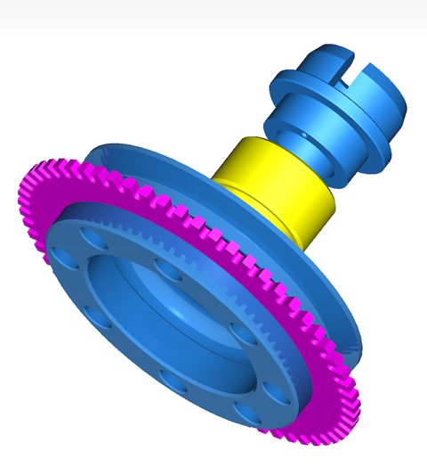
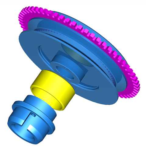
Next up, look at the VR sensor support bracket, chase up the pistons, and hopefully acquire a boring machine.
Ultimately I need to fit a crankshaft timing trigger to this engine, as part of the ongoing ignition & fuelling developments, and the traditional locations for these are the flywheel or front pulley. If I want to gear this up for retrospective and easy fitment, the flywheel really is out of the question, because this is an engine out exercise in a Panhard, and that is a no brainer.
That now means the front pulley arrangement has the most potential, and that is what the majority of modern car manufacturers use anyway. Although it is possible to add a trigger wheel to the existing pulley, like I have done in my bench testing to date, there is a slight variance in sizes that negates this. It’s my philosophy to always make new parts wherever possible, so that old ones don’t get destroyed unnecessarily. At the same time there might be other design changes or benefits you can bring to this area, so for example I can incorporate a modern oil seal, assuming you tweak the timing gear casing, and also make the pulley rebuildable. If this is not to your liking, and you want to keep the OEM piston ring seal the design can be modified to accommodate this too, by replacing the yellow part for another.
Latest CAD thoughts are pictured below, and the pulley now has a renewable inner ring shown in yellow, which acts as a running surface for the double lipped oil seal. The aluminium parts in blue now have a location dowel for timing purposes. The trigger wheel shown in purple is also a standard 60-2 pattern, which gives improved triggering over the lesser toothed versions I was experimenting with.
Next up, look at the VR sensor support bracket, chase up the pistons, and hopefully acquire a boring machine.
Panhard trigger wheel testing
Sunday 02 October 2011 Filed in: Panhard Ignition
Another few hours spent on this, testing various iterations of the firmwares with my cased MicroSquirts, and revisiting yesterdays efforts, as I made a number of teeth input error part way through my previous attempts. This only affects the early B&G firmware and MSExtra as they need the correct value inputting, whereas the later B&G 3.760 has an auto detect function called Auto Trigger.
A quick screenshot of TunerStudio doing its stuff using the logging tools. The cyan columns are the 11 teeth, the gap the 12th missing tooth, and the red line on the bottom is the Sync errors, and because this line is straight there are none. Using MSExtra 3.1.0, I can get reliable sync from 45 rpm up to 11800 rpm using the Renault sensor and a 2mm air gap. I think if the trigger wheel is made thicker, it will allow me to increase the air gap to nearer 3mm, and I might make the teeth slightly less wide too.

The screenshot below shows the tooth pattern, the 11vertical lines roughly the same size are the physical bumps or teeth, and the tallest column is the missing tooth area. This is what the ECU is seeing, but as this is using the motorised engine rig, so the variances between the 11 teeth are not very pronounced. However when this is used on a real engine the compression effects and the resulting slowing down of the trigger wheel attached to the crankshaft, shows itself in bigger variances in height.
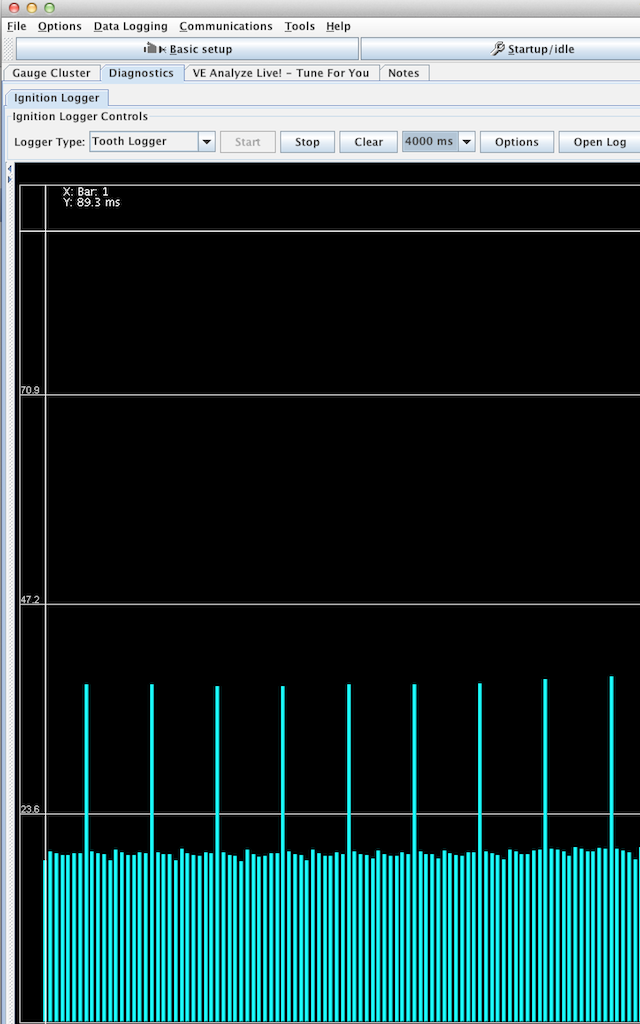
A quick screenshot of TunerStudio doing its stuff using the logging tools. The cyan columns are the 11 teeth, the gap the 12th missing tooth, and the red line on the bottom is the Sync errors, and because this line is straight there are none. Using MSExtra 3.1.0, I can get reliable sync from 45 rpm up to 11800 rpm using the Renault sensor and a 2mm air gap. I think if the trigger wheel is made thicker, it will allow me to increase the air gap to nearer 3mm, and I might make the teeth slightly less wide too.
The screenshot below shows the tooth pattern, the 11vertical lines roughly the same size are the physical bumps or teeth, and the tallest column is the missing tooth area. This is what the ECU is seeing, but as this is using the motorised engine rig, so the variances between the 11 teeth are not very pronounced. However when this is used on a real engine the compression effects and the resulting slowing down of the trigger wheel attached to the crankshaft, shows itself in bigger variances in height.
Panhard crankshaft pulley on EFI rig
Saturday 01 October 2011 Filed in: Panhard Ignition
I managed to get a few timing wheels laser cut the other day, and the idea was to combine these with a Renault crankshaft sensor, so that I can create a timing trigger for the electronic ignition. I had done this with an earlier project, but now wanted to refine the set up further to allow for the fuel injection mods that will follow from this.
Here’s a pic of the first design effort, and there’s me thinking that a 3mm thick wheel would be sufficient for a 2mm sensor tip. At first it didn’t seem like it would be, and the disturbing thing is there is a slight eccentricity with these OEM pulleys, so a wider wheel might be useful to combat this. The reason why it wasn’t working as well as it should have done, was because I was putting the wrong values into the Number of Teeth box. I was inputting 8-1, when it was plainly a 12-1 wheel!

I was also swapping various v2 MicroSquirts & a v3 beta running different EFI firmwares including MSExtra 3.1 and, B&G 2.890, 3.430 & 3.760.
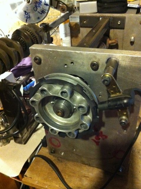
This 12-1 wheel design worked OK up to 3000 rpm, but then dropped out of sync, whereas the 6mm thick 36-1 wheel using the same sensor worked faultlessly from 50-11780 rpm, so despite the initial input error, the trigger wheel is too thin.
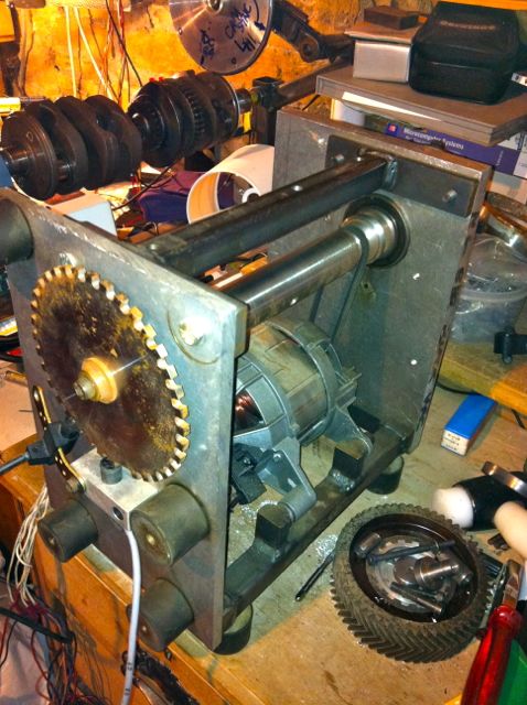
This is the old washing machine motor from a 1986 Hotpoint ℅ Siemens Gmbh dropped into my DIY engine rig. I have had to fit a poly-vee belt reduction gear, as this thing will rev to 22,000 RPM in 1:1 mode!
Note. Bottom right, inside the chevron cut fibre camshaft timing gear are the revised oil light pistons I made in the 1990’s to combat the lubrication faults with the Panhard engine. The picture below shows an incomplete one, with the revised lubrication to the timing gear (there is a relief valve, ball, spring with a set screw yet to be inserted in the middle).
Also can you spot the crankshaft & cam rig in the background, above this picture, which is still being used to develop the MicroSquirt based EFI systems for the GTS1000 & Thunderace motorcycle engines
Here’s a pic of the first design effort, and there’s me thinking that a 3mm thick wheel would be sufficient for a 2mm sensor tip. At first it didn’t seem like it would be, and the disturbing thing is there is a slight eccentricity with these OEM pulleys, so a wider wheel might be useful to combat this. The reason why it wasn’t working as well as it should have done, was because I was putting the wrong values into the Number of Teeth box. I was inputting 8-1, when it was plainly a 12-1 wheel!
I was also swapping various v2 MicroSquirts & a v3 beta running different EFI firmwares including MSExtra 3.1 and, B&G 2.890, 3.430 & 3.760.
This 12-1 wheel design worked OK up to 3000 rpm, but then dropped out of sync, whereas the 6mm thick 36-1 wheel using the same sensor worked faultlessly from 50-11780 rpm, so despite the initial input error, the trigger wheel is too thin.
This is the old washing machine motor from a 1986 Hotpoint ℅ Siemens Gmbh dropped into my DIY engine rig. I have had to fit a poly-vee belt reduction gear, as this thing will rev to 22,000 RPM in 1:1 mode!
Note. Bottom right, inside the chevron cut fibre camshaft timing gear are the revised oil light pistons I made in the 1990’s to combat the lubrication faults with the Panhard engine. The picture below shows an incomplete one, with the revised lubrication to the timing gear (there is a relief valve, ball, spring with a set screw yet to be inserted in the middle).
Also can you spot the crankshaft & cam rig in the background, above this picture, which is still being used to develop the MicroSquirt based EFI systems for the GTS1000 & Thunderace motorcycle engines
Panhard oil light piston wear update
Friday 23 September 2011 Filed in: Panhard Oil
The original oil light was a machined cast lump…
so I created this replacement in mild steel. This is the basic part, because I hand finish this further.
This is used with other mods to refine the Panhard oil lubrication circuits. The nose was rounded in the picture below to prevent wearing out the wooden plug that pushes the oil light contact, once the engine gets up to pressure.
I happened to be stripping an engine to use in my EFI project, and I came across this, which was an earlier prototype 1990’s part that I fitted to an engine in 2002, and because I was relying on splash and bleeding from the oil ways nearby, it didn’t need the cross drilling.
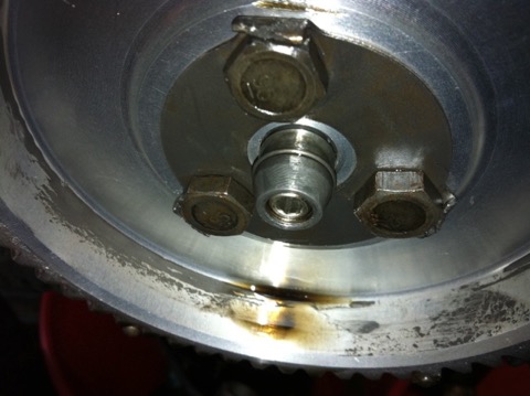
Interestingly, there is no wear to the wooden block below, and additionally there is no cross drilling to increase the oil supply to the camshaft timing gears this version, whereas there was in later engines I built. One of the reasons for examining this, was the owner said the camshaft gear was noisier than he remembered previously, and although the aluminium gear is when compared against the OEM fibre wheel, I’d thought I’d investigate further.

Picture above shows the oil light insulator button from inside the camshaft timing gear case, which acts an insulator and breaks the brass contact for the dash mounted low oil pressure warning light earth loop, but only as the oil pressure in the hollow camshaft gallery builds up.
It’s more remarkable, because this particular engine had very little additional lubrication, other than a little splash bleed from nearby oil galleries, and was the first one where I altered the crankcase lubrication circuits.
This is great news, as I now don’t need to do the brass nosing mod, as shown below, which I did in 2004.
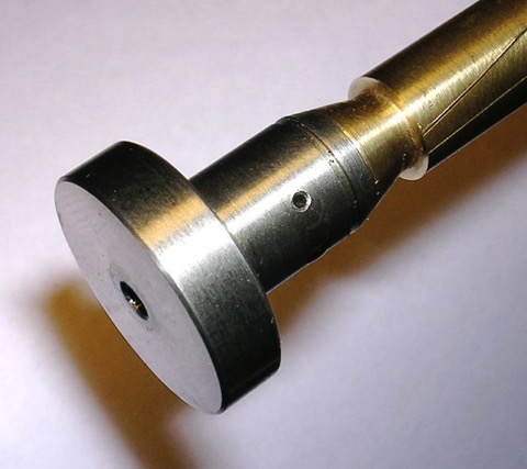
This was done to an earlier engine rebuild for a two bladed fan Dyna engine, because I was concerned about the potential friction that the hollow threaded tip of the piston might create.
This is the later revision to the oil light circuit, and although it’s incomplete, you can see there is a cross drilling that is exposed once the oil pressure builds up in the camshaft gallery. The relief valve can be set, so that the first priority is the crankshaft big end rollers, and the hole size can be varied if more lubrication is needed to these timing gears. However, as this oil feed is off the central oil gallery within the camshaft, there is no pressure fluctuations as the camshaft rotates to either big end bearing, so eliminating all the developmental faults that were introduced as the years went by.
so I created this replacement in mild steel. This is the basic part, because I hand finish this further.
This is used with other mods to refine the Panhard oil lubrication circuits. The nose was rounded in the picture below to prevent wearing out the wooden plug that pushes the oil light contact, once the engine gets up to pressure.
I happened to be stripping an engine to use in my EFI project, and I came across this, which was an earlier prototype 1990’s part that I fitted to an engine in 2002, and because I was relying on splash and bleeding from the oil ways nearby, it didn’t need the cross drilling.
Interestingly, there is no wear to the wooden block below, and additionally there is no cross drilling to increase the oil supply to the camshaft timing gears this version, whereas there was in later engines I built. One of the reasons for examining this, was the owner said the camshaft gear was noisier than he remembered previously, and although the aluminium gear is when compared against the OEM fibre wheel, I’d thought I’d investigate further.
Picture above shows the oil light insulator button from inside the camshaft timing gear case, which acts an insulator and breaks the brass contact for the dash mounted low oil pressure warning light earth loop, but only as the oil pressure in the hollow camshaft gallery builds up.
It’s more remarkable, because this particular engine had very little additional lubrication, other than a little splash bleed from nearby oil galleries, and was the first one where I altered the crankcase lubrication circuits.
This is great news, as I now don’t need to do the brass nosing mod, as shown below, which I did in 2004.
This was done to an earlier engine rebuild for a two bladed fan Dyna engine, because I was concerned about the potential friction that the hollow threaded tip of the piston might create.
This is the later revision to the oil light circuit, and although it’s incomplete, you can see there is a cross drilling that is exposed once the oil pressure builds up in the camshaft gallery. The relief valve can be set, so that the first priority is the crankshaft big end rollers, and the hole size can be varied if more lubrication is needed to these timing gears. However, as this oil feed is off the central oil gallery within the camshaft, there is no pressure fluctuations as the camshaft rotates to either big end bearing, so eliminating all the developmental faults that were introduced as the years went by.
Panhard crankshaft pulley with trigger wheel
Wednesday 21 September 2011 Filed in: Panhard Ignition
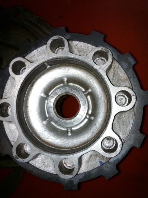
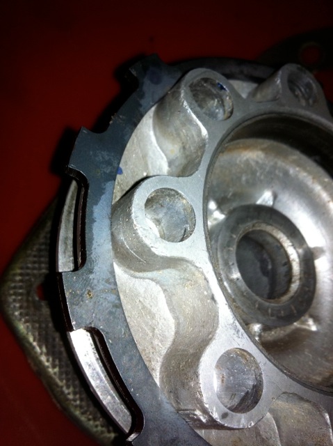
Panhard cylinder
Saturday 09 July 2011 Filed in: Panhard Cylinder
Panhard cylinder heads and barrels are a one piece assembly, very similar to early aero engines, which incidentally removes any chance of head gasket failures, but this makes machining them awkward. Technology has moved on and it’s not the norm to manufacture engines like this, and in fact Porsche engines pro rata manage to make more horsepower using similar materials incorporating head gaskets, without suffering from reliability issues.
For my engine work, it was always going to be necessary to revisit the cylinder construction, and again many years ago I separated a head from a cylinder, as a design exercise to investigate the feasibility of modifying these components, and making new parts. I remember doing this in the lathe, and the cooling fins from the barrel only just cleared the toolholder, but when they were separated and you could see the individual pieces, it was obvious to me this was the only way to go, if you wanted to bring the engines into the 21st century. Panhard tapered the liners, and used split skirt pistons with hemispherical combustion chambers, which was OK in the 1940s, but current combustion chamber thinking is moving towards minimal surface areas and squish, with reduced ignition advance.
Cylinder and coating technology has moved on as well, so whereas VW would use a Biral cylinder in the 80’s, quite similar to a Panhard with a steel liner and aluminium finning, others in motorcycling and karting were using all aluminium construction for their cylinder construction with Nikasil plating for the piston surfaces. Early plating processes were responsible for a few engine failures over time, with plating separation at the head gasket/ cylinder interfaces causing all sorts of issues, especially in higher performance engines with detonation.
Fortunately, thanks in part to the space programme and the accelerated development of ceramics, there are better alternatives available now with amazing potential. Aluminium is now used in tool steel injection moulding machines with coatings applied, that offer better thermal and longer life than their steel equivalents, plus the coating deposition processes have become much better environmentally and from a tribological viewpoint are now second to none and so used extensively in high performance engines.
What does this mean for Panhards, well you could remove the heads, make new cylinders with increased finning to dissipate the heat, just like others did in WWII, as air cooled engine performance was boosted in fighter aircraft. At the same time, eliminate the steel liner using modern coating technology, and safely increase the performance margins, as a cooler cylinder would keep heat away from the cylinder heads, and no liner would negate differing thermal expansion rates. The coatings technology would secure long life, corrosion protection and a restoration route if required.
A standard cylinder has eight fins under the head like the drawing below.
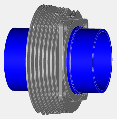
Mine will have...well you have to wait! Anyway there are other priorities first, because there’s no use making cylinders that increase performance, as the crankshaft is undoubtedly the weakest link. Peter Breed in Holland offers a first class crankshaft service, with bespoke connecting rods and new pistons to rebored OEM cylinders. It is a good system, and was the most cost effective route at the time, and probably still is. How do I know, well I worked with Peter on this solution, but it relies on a having a salvageable crankshaft at the start and that’s why I am developing a new remanufacturing process, because I want to salvage these tired, pitted and corroded crankshafts.
For my engine work, it was always going to be necessary to revisit the cylinder construction, and again many years ago I separated a head from a cylinder, as a design exercise to investigate the feasibility of modifying these components, and making new parts. I remember doing this in the lathe, and the cooling fins from the barrel only just cleared the toolholder, but when they were separated and you could see the individual pieces, it was obvious to me this was the only way to go, if you wanted to bring the engines into the 21st century. Panhard tapered the liners, and used split skirt pistons with hemispherical combustion chambers, which was OK in the 1940s, but current combustion chamber thinking is moving towards minimal surface areas and squish, with reduced ignition advance.
Cylinder and coating technology has moved on as well, so whereas VW would use a Biral cylinder in the 80’s, quite similar to a Panhard with a steel liner and aluminium finning, others in motorcycling and karting were using all aluminium construction for their cylinder construction with Nikasil plating for the piston surfaces. Early plating processes were responsible for a few engine failures over time, with plating separation at the head gasket/ cylinder interfaces causing all sorts of issues, especially in higher performance engines with detonation.
Fortunately, thanks in part to the space programme and the accelerated development of ceramics, there are better alternatives available now with amazing potential. Aluminium is now used in tool steel injection moulding machines with coatings applied, that offer better thermal and longer life than their steel equivalents, plus the coating deposition processes have become much better environmentally and from a tribological viewpoint are now second to none and so used extensively in high performance engines.
What does this mean for Panhards, well you could remove the heads, make new cylinders with increased finning to dissipate the heat, just like others did in WWII, as air cooled engine performance was boosted in fighter aircraft. At the same time, eliminate the steel liner using modern coating technology, and safely increase the performance margins, as a cooler cylinder would keep heat away from the cylinder heads, and no liner would negate differing thermal expansion rates. The coatings technology would secure long life, corrosion protection and a restoration route if required.
A standard cylinder has eight fins under the head like the drawing below.
Mine will have...well you have to wait! Anyway there are other priorities first, because there’s no use making cylinders that increase performance, as the crankshaft is undoubtedly the weakest link. Peter Breed in Holland offers a first class crankshaft service, with bespoke connecting rods and new pistons to rebored OEM cylinders. It is a good system, and was the most cost effective route at the time, and probably still is. How do I know, well I worked with Peter on this solution, but it relies on a having a salvageable crankshaft at the start and that’s why I am developing a new remanufacturing process, because I want to salvage these tired, pitted and corroded crankshafts.
Panhard crankshaft pulley
Sunday 03 July 2011 Filed in: Panhard Ignition
I recently bought a newer CAD package, so rather than use Ashlar Vellum from the late 80’s on a G4 Cube, I can now use my Intel iMac & MacBook Pro, which are significantly faster. The software also has a number of export options, and I recently did a test .dxf file export to a laser cutting company, and everything translated between the differing computer platforms & softwares flawlessly. The parts were used in the engine stand.
To get used to the software some more, I started to redraw some Panhard components, that I had drawn up years ago, but were in the older format. This is the start of the new dynamo pulley, which is really going to become an alternator pulley. It should be obvious which is which if you’ve seen the components before, but original part is the bottom image, with the my updated version on top.
Final timing gear design, 60-2 drawn, or pulley drive belt section not fixed yet, as aftermarket low cost alternator or the VR sensor location isn’t finalised.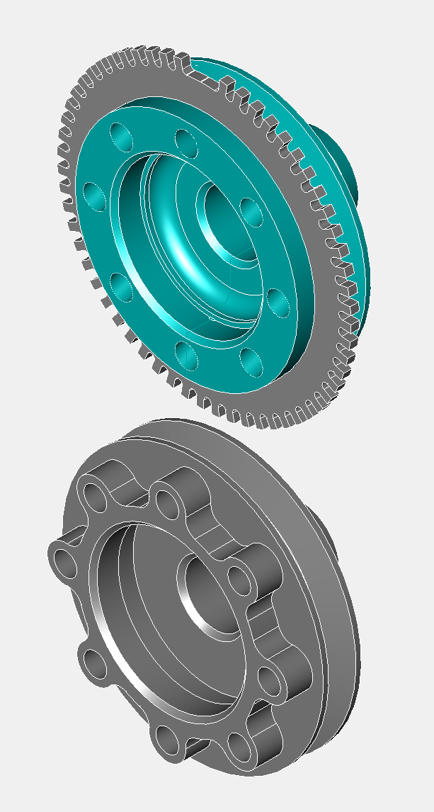
Panhard engine stand developments
Thursday 30 June 2011 Filed in: Dyno
A long time ago I needed to test my Panhard engines, and as I didn’t have a car on the road, an engine dyno would have been the next best thing. However finding one is another story, so I did the next best thing, found a roller dyno and thought about making an engine frame that’ll drive it. I was lucky there was an inertial dyno about two miles from me, but I never did get chance to make the “motorised wheelbarrow” that would bolt to it, as I put the engine in a Panhard PL17 and it worked so well, that it was obvious at the time there were improvements, so the need to construct something fell by the wayside.
Fast forward several years later, fuel injection projects on my motorcycle engines, FZR1000, GTS1000 & YZF1000, mean an engine dyno is an essential requirement to do this work properly. As I won’t be putting a Panhard on the road short term, and I’d like to benchmark these engines too, so it makes sense to revisit the engine dyno project again, but allow for & consider both these options at the same time.
The bike engine is straightforward as it is chain driven, but the Panhard isn’t, so I’d have to convert the flywheel to accept chain drive, as you can see in the picture below. This is the unfinished raw metal version complete with a dummy engine, which is a partial crankcase and a split cylinder & head from another project. I needed to make sure the engine support plate cleared the inlet manifold stubs, which it does now.
The engine frame is not fastened to the wheel subframe when the picture was taken, and neither is the sprocket is, as I am trying to keep the chain tension and length the same for any combo of engine rig I use, and I need to keep disassembling the stand and fitting other parts. If I can keep the same chain, it will simplify the swap over process, and so make the installation of other engines easier. Additionally, I am going to convert this into a freestanding engine stand, so I need to make a simple rear support frame, which will probably be a folding structure, probably like an ironing board stand, that tucks out of the way as I slide the engine rig onto the wheel rig. This means I can do basic run tests without the dyne, and free up dyne room for other projects.
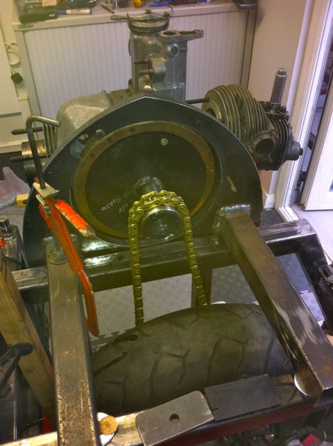
In the latest pic, everything seems to check out, as I now have a virtually complete engine fitted. It looks like I don’t need any extra brackets welding to the frame other than a battery support & the associated control panel shelf, so I will be sending it off to the powder coaters soon. Alternator conversion was a previous modification that had been dormant for a few years too, and it was a nice tidy fit at the time, however it’s powered by Lucas, so that probably won’t appeal to our French cousins! However these alternators are great value for money compared to the smaller Denso units, and readily available.
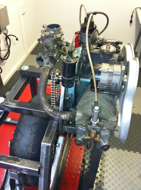
Fast forward several years later, fuel injection projects on my motorcycle engines, FZR1000, GTS1000 & YZF1000, mean an engine dyno is an essential requirement to do this work properly. As I won’t be putting a Panhard on the road short term, and I’d like to benchmark these engines too, so it makes sense to revisit the engine dyno project again, but allow for & consider both these options at the same time.
The bike engine is straightforward as it is chain driven, but the Panhard isn’t, so I’d have to convert the flywheel to accept chain drive, as you can see in the picture below. This is the unfinished raw metal version complete with a dummy engine, which is a partial crankcase and a split cylinder & head from another project. I needed to make sure the engine support plate cleared the inlet manifold stubs, which it does now.
The engine frame is not fastened to the wheel subframe when the picture was taken, and neither is the sprocket is, as I am trying to keep the chain tension and length the same for any combo of engine rig I use, and I need to keep disassembling the stand and fitting other parts. If I can keep the same chain, it will simplify the swap over process, and so make the installation of other engines easier. Additionally, I am going to convert this into a freestanding engine stand, so I need to make a simple rear support frame, which will probably be a folding structure, probably like an ironing board stand, that tucks out of the way as I slide the engine rig onto the wheel rig. This means I can do basic run tests without the dyne, and free up dyne room for other projects.
In the latest pic, everything seems to check out, as I now have a virtually complete engine fitted. It looks like I don’t need any extra brackets welding to the frame other than a battery support & the associated control panel shelf, so I will be sending it off to the powder coaters soon. Alternator conversion was a previous modification that had been dormant for a few years too, and it was a nice tidy fit at the time, however it’s powered by Lucas, so that probably won’t appeal to our French cousins! However these alternators are great value for money compared to the smaller Denso units, and readily available.
Panhard rebirth
Thursday 23 June 2011 Filed in: Blog Comments
Panhard work is being restarted and now I’m going to get serious. It’s been a long time coming, but thanks to my other interests, I have some new tricks up my sleeve…traditionalists beware. Read More...
Panhard retrospective
Monday 12 November 2007 Filed in: Blog Comments
Going to add a few pages about Panhards in the next few days. I used to play with these some years ago, and would love to do more with them, but they have to stay on the back burner for longer yet. Greetings to fellow Panhard enthusiasts the world over. My speciality was tuning and redesigning the oil lubrication circuits, including an oil filter conversion. I also converted a Citroen 2CV electronic ignition and adapted it to fit a Panhard.
I will update this page with a catalogue of retrospective images when I find them, and a take a few pics of the development parts I made.
I will update this page with a catalogue of retrospective images when I find them, and a take a few pics of the development parts I made.
Panhard oil light piston developments
Friday 02 April 2004 Filed in: Panhard Oil
As part of my lubrication works I made some oil light pistons to replace the standard machined cast originals shown in the bottom picture.
The original had a rounded tip, whereas mine had a threaded hole, which was part of the oil relief valve assembly, and I couldn’t really alter this unless I made a two part piston.
There was a concern that this nosing or tip, despite being rounded similar to the picture below …
… would still abrade the oil light wooden button, and cause problems further down the line. To negate this I started work on a one off two part oil light piston assembly.
First I had to replace the set screw and create a guide for the relief valve spring. I made this part in brass using the lathe from a piece I had lying around that I was going to use to replace a missing foot off my favourite briefcase!
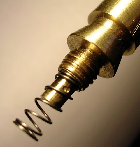
Then cut down a replacement oil light piston, and put them together, to look like this.
This was the finished product within the camshaft gear...
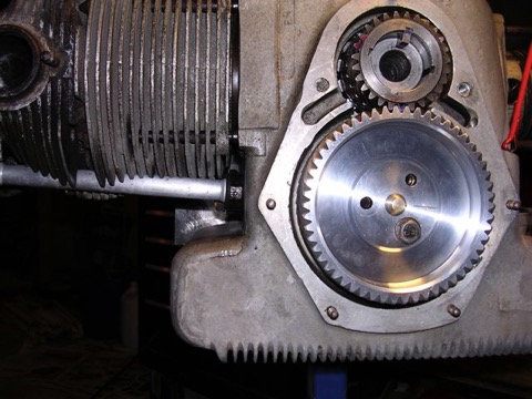
…and here is a close up.
UPDATE (2011) Link to this post
It turns out this wasn’t necessary, as upon examining another early engine, with this rounded oil light piston tip fitted there was no wear to the wooden block, so this work wasn’t required, but at least there is another option for those that don’t believe me.
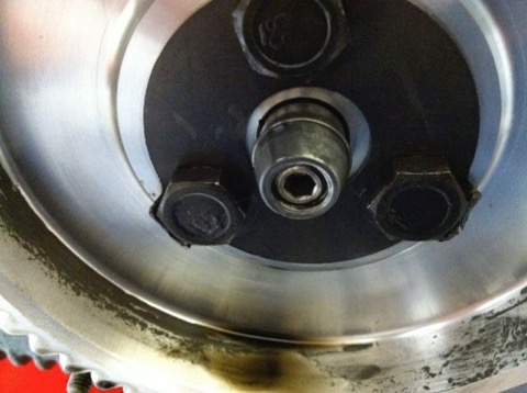
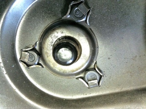
The original had a rounded tip, whereas mine had a threaded hole, which was part of the oil relief valve assembly, and I couldn’t really alter this unless I made a two part piston.
There was a concern that this nosing or tip, despite being rounded similar to the picture below …
… would still abrade the oil light wooden button, and cause problems further down the line. To negate this I started work on a one off two part oil light piston assembly.
First I had to replace the set screw and create a guide for the relief valve spring. I made this part in brass using the lathe from a piece I had lying around that I was going to use to replace a missing foot off my favourite briefcase!
Then cut down a replacement oil light piston, and put them together, to look like this.
This was the finished product within the camshaft gear...
…and here is a close up.
UPDATE (2011) Link to this post
It turns out this wasn’t necessary, as upon examining another early engine, with this rounded oil light piston tip fitted there was no wear to the wooden block, so this work wasn’t required, but at least there is another option for those that don’t believe me.
