Oct 2012
Panhard Cylinder Liner Rebore Update 6
28/10/12 15:08 Filed in: Panhard Piston | Whatton
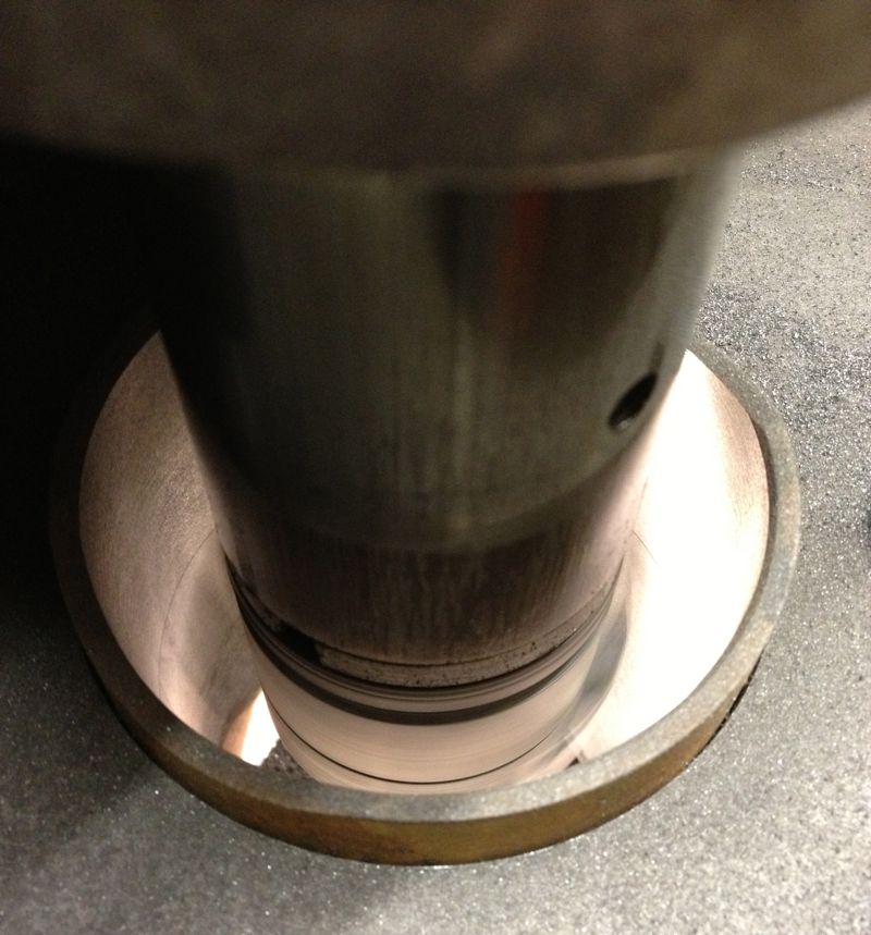
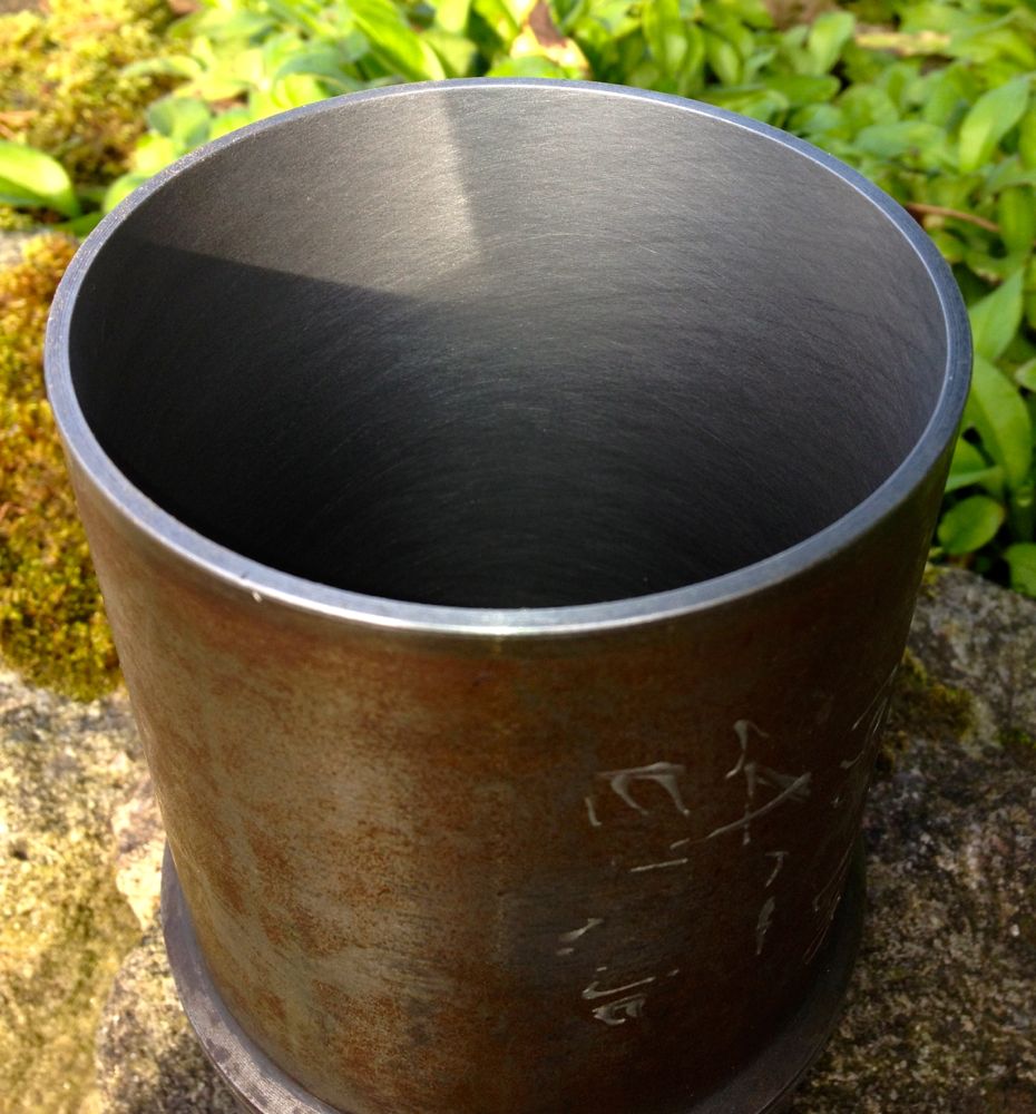
Yesterday, I machined a couple of test liners from an early Dyna engine, and after inspecting them, I decided I would do a test fit in the aluminium cylinder to see what difference there was in the bore diameter due to the interference fit.
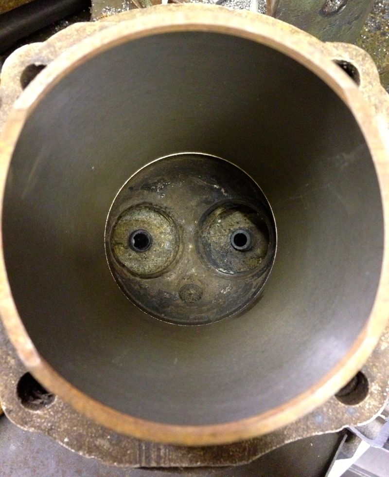
After warming up the bare cylinder with the big propane torch, I placed the cylinder in, and rotated it into the correct position (these liners have cut outs for the crankshaft webs).
Once it was cool, I decided to take a remeasure, and see how the dimensions compared.
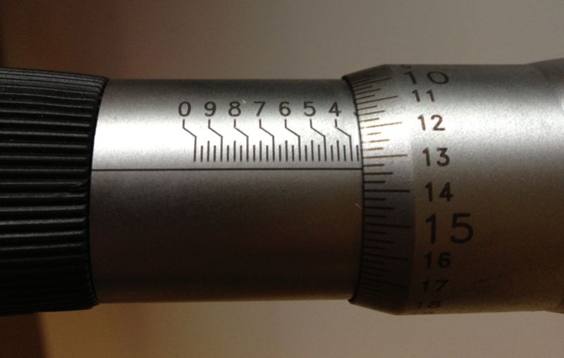
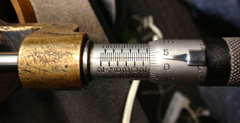
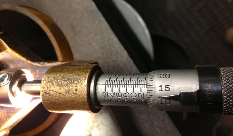
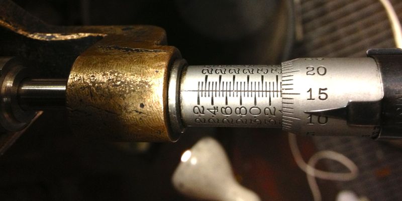
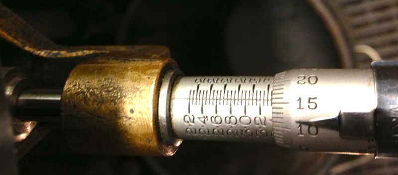
I started off with this measurement from yesterday, but when the sleeve or liner was placed in the cylinder I got the measurement in the second picture below.
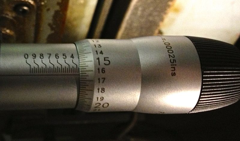
To be honest, I thought the cylinder was larger than this picture above when I measured it this morning at around the “17.25” mark, which represents 3.36725”, but for some reason I have mislaid the picture.
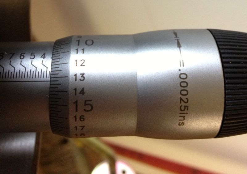
Either way this represents a 0.003”-0,004” squeeze depending what picture I look at, and as I moved the micrometer out of the cylinder and took further measurements along the way, I got the following…
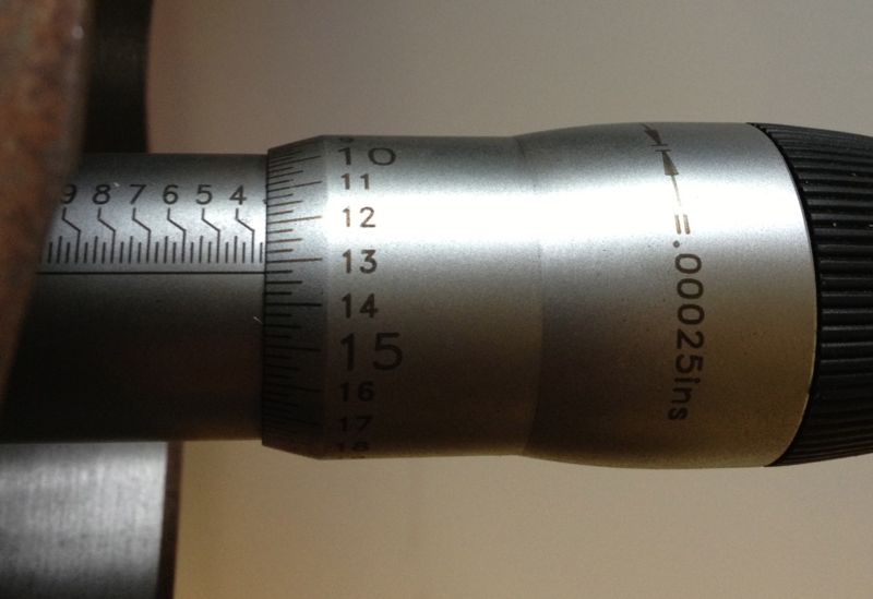
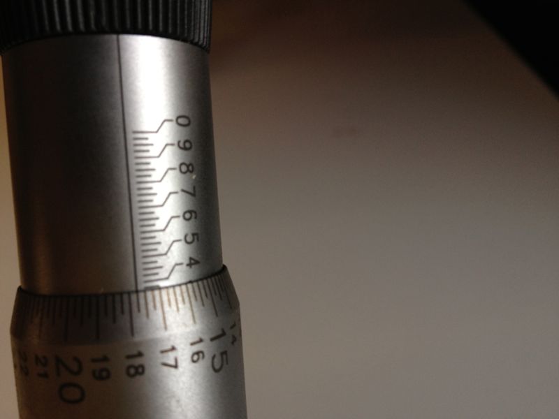
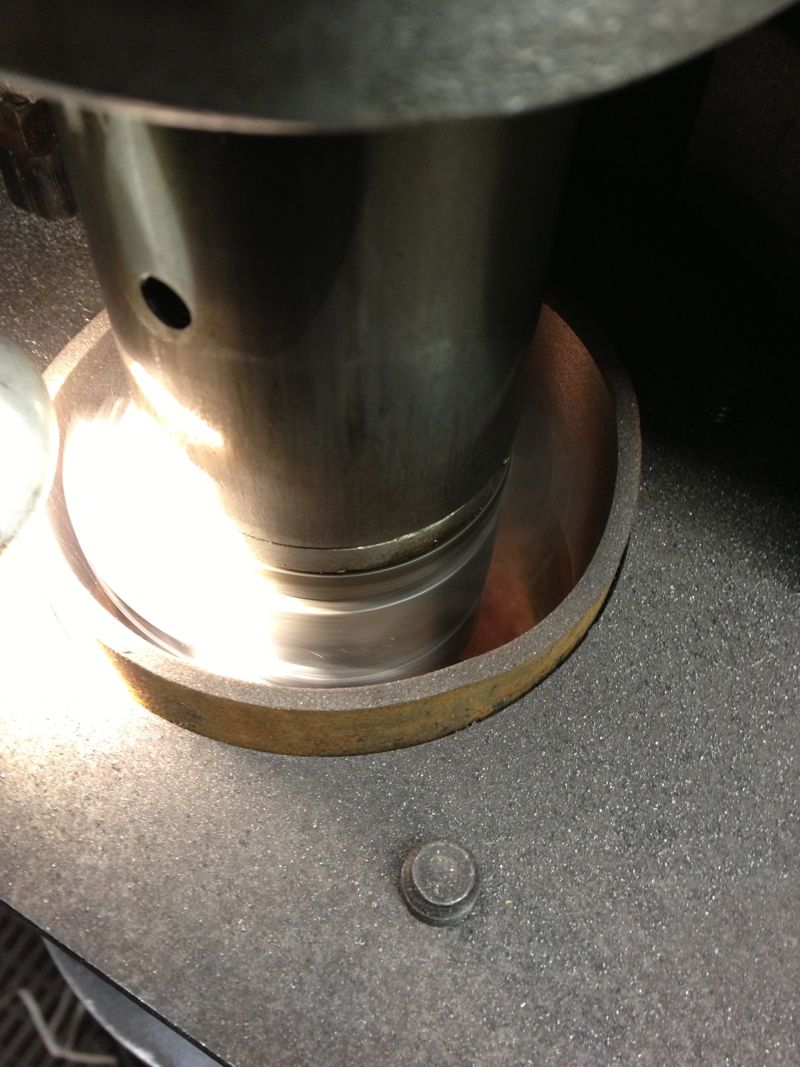
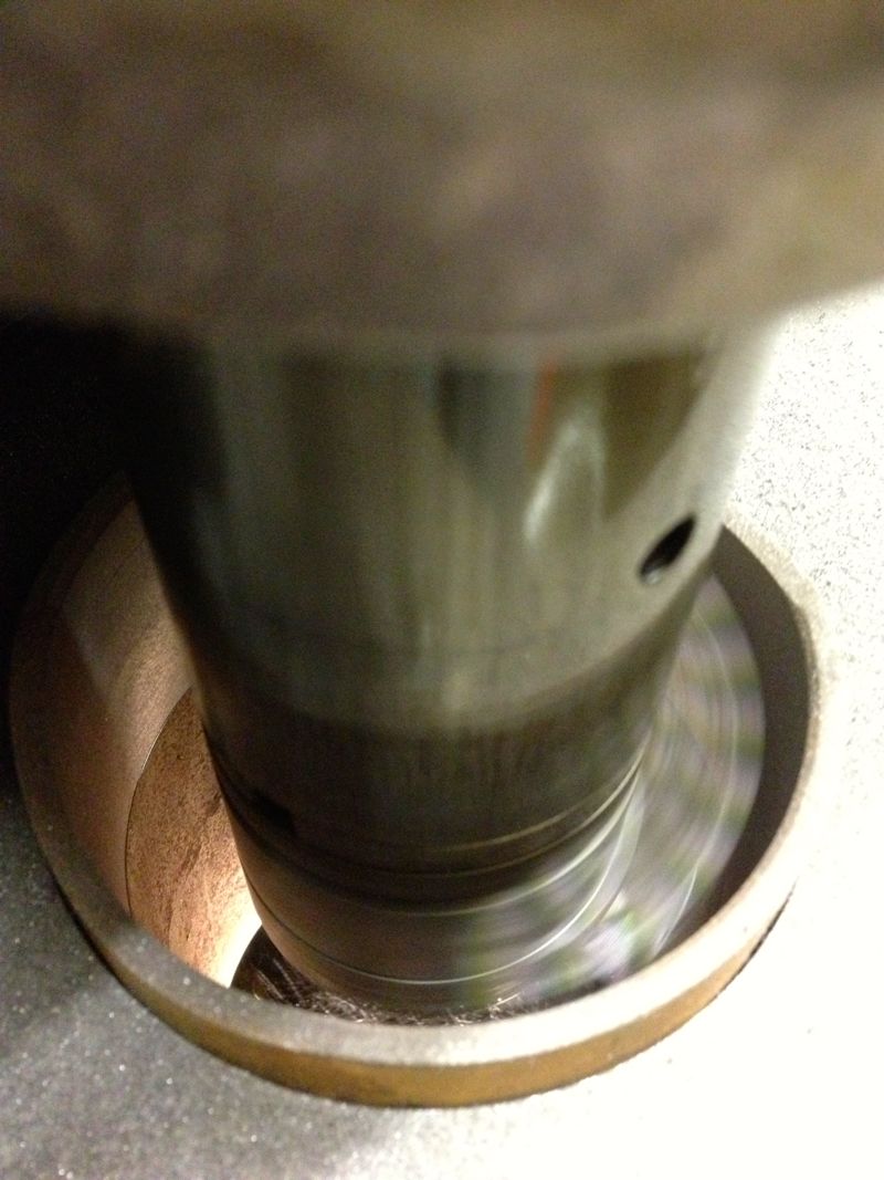
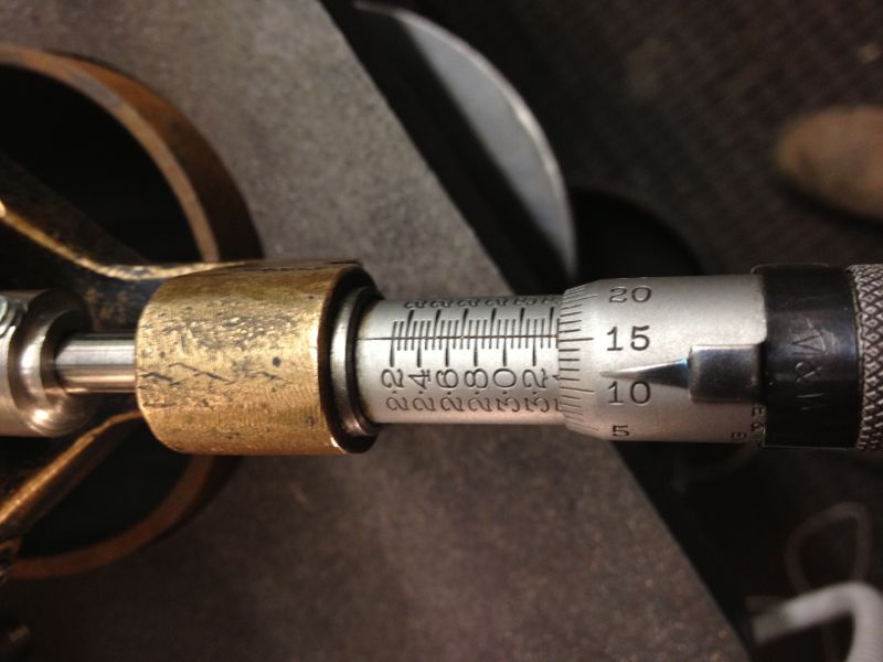
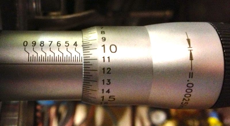
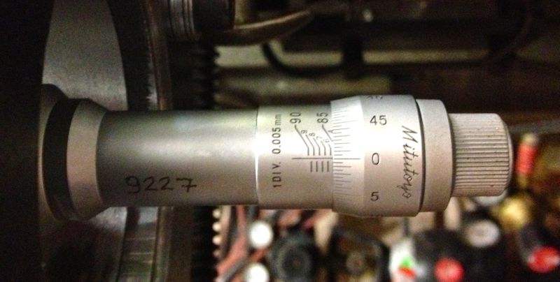
As the liner left the grip of the cylinder the sleeve opened up, as shown below.
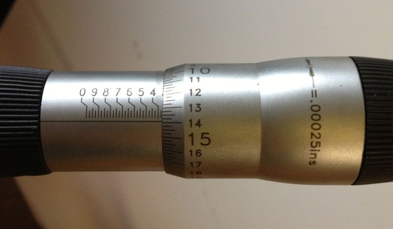
At the skirt perimeter it measured even bigger still at 3.36775”, but this isn’t a huge deal, but it is interesting that a parallel bored liner deflects this much.
So yet again, we have the issue of an interference fit and the folklore surrounding a tapered bore. The last liner I machined using the Whatton actually produced a tapered bore, and the taper runs in the right direction too, because it is smallest at the hottest end.
I now know how to achieve this, and after playing with the Whatton some more, i have ascertained why it is happening. Anyway, it is an accidental product of my curiosity, and what relevance it has on real world engines is unproven. I will explore this option when the engine dyno test facility is up and running, to see if it is beneficial.
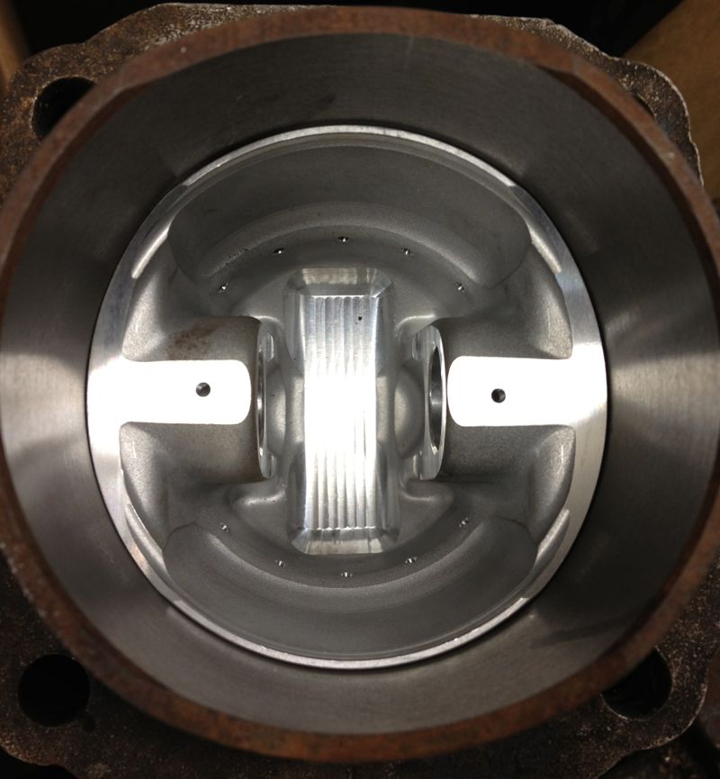
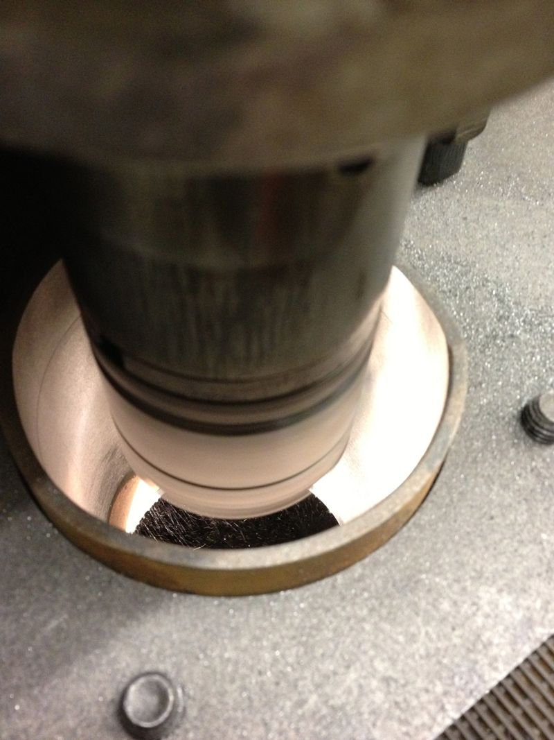
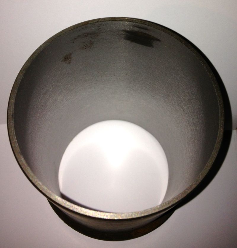
On the subject of taper, here are two pictures of a bare piston in the cylinder liner, but turned through 90º. Notice the difference in the resting height, this is due to the ovality of the piston, and the bore being smaller than the pistons nominal diameter of 85.4mm or 3.3622”
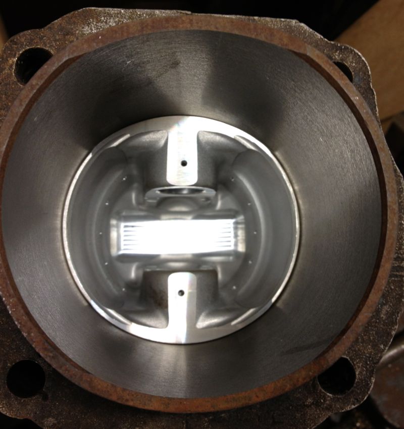
Obviously with the interference fit, the liner is slightly smaller than the expected size, as it reads 3.36320” diameter over it’s running surface, and it’s recommended value of 85.5mm equates to 3.36614”, so it’s 0.003“ undersize, or operating on a 0.001” piston to bore clearance. Actually, in modern 2 valve race engines, with very light pistons and a better spec liner material, I have seen 0.0015” clearance on an air-cooled V twin.
It did seize, because of a fuelling error, which caused it to run too hot and the piston grabbed in the bore. It was a real nice engine, but I cannot say how many horses it had at the wheel, but it was over 10% of its capacity in cubic centimetres measured in DIN RWHP, and all from a two valve head.
After warming up the bare cylinder with the big propane torch, I placed the cylinder in, and rotated it into the correct position (these liners have cut outs for the crankshaft webs).
Once it was cool, I decided to take a remeasure, and see how the dimensions compared.
I started off with this measurement from yesterday, but when the sleeve or liner was placed in the cylinder I got the measurement in the second picture below.
To be honest, I thought the cylinder was larger than this picture above when I measured it this morning at around the “17.25” mark, which represents 3.36725”, but for some reason I have mislaid the picture.
Either way this represents a 0.003”-0,004” squeeze depending what picture I look at, and as I moved the micrometer out of the cylinder and took further measurements along the way, I got the following…
As the liner left the grip of the cylinder the sleeve opened up, as shown below.
At the skirt perimeter it measured even bigger still at 3.36775”, but this isn’t a huge deal, but it is interesting that a parallel bored liner deflects this much.
So yet again, we have the issue of an interference fit and the folklore surrounding a tapered bore. The last liner I machined using the Whatton actually produced a tapered bore, and the taper runs in the right direction too, because it is smallest at the hottest end.
I now know how to achieve this, and after playing with the Whatton some more, i have ascertained why it is happening. Anyway, it is an accidental product of my curiosity, and what relevance it has on real world engines is unproven. I will explore this option when the engine dyno test facility is up and running, to see if it is beneficial.
On the subject of taper, here are two pictures of a bare piston in the cylinder liner, but turned through 90º. Notice the difference in the resting height, this is due to the ovality of the piston, and the bore being smaller than the pistons nominal diameter of 85.4mm or 3.3622”
Obviously with the interference fit, the liner is slightly smaller than the expected size, as it reads 3.36320” diameter over it’s running surface, and it’s recommended value of 85.5mm equates to 3.36614”, so it’s 0.003“ undersize, or operating on a 0.001” piston to bore clearance. Actually, in modern 2 valve race engines, with very light pistons and a better spec liner material, I have seen 0.0015” clearance on an air-cooled V twin.
It did seize, because of a fuelling error, which caused it to run too hot and the piston grabbed in the bore. It was a real nice engine, but I cannot say how many horses it had at the wheel, but it was over 10% of its capacity in cubic centimetres measured in DIN RWHP, and all from a two valve head.
Comments
Panhard Cylinder Liner Rebore Update 5
27/10/12 18:47 Filed in: Panhard Piston | Whatton
Using the freshly extracted & cooled cylinder liners from today, I loaded one into the Whatton boring machine jig, and started to centralise the Whatton to the liner. I usually drop the bar into the liner, centralise the machine using the three point cats paws, and tighten the base onto the mill bed.
I decided on an arbitrary test bore of 3.353” for the first cut, which is approximately 85.1mm, and just a bit oversize on the original liners.
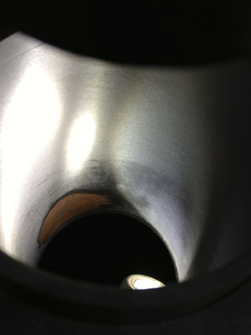
I then started to machine the liner, but I noticed that the cut was greater on one side and not removing material from the opposite side, so I decided to recenter the Whatton at the top of the liner held in the rig. This is actually the bottom of the liner in reality...
You can see the slight ring at the top in this picture above, when I centred the liner at the top of rig, and in the picture below, the area missed in the machining.
Obviously, further machining is required, but whether it will remove this blemish inside the liner is not known until you try, so it’s time to reset the cutting tip and see if cutting a slightly larger diameter will do it. New diameter is set at 3.3665”, as shown below, by sliding the tooltip out towards the micrometer.
and then after tightening the tooltip locking screw, a quick recheck, but there’s not much difference here, about a thou, so it’s now reading 3.3655” as shown below.
Notice how the top step is taken out by machining a larger diameter, but what will happen later on?
So when the second cut is finished, I let the tooltip pass through the liner & bottom mounting plate, and recheck the tooltip bore diameter, which hasn’t changed and reads 3.3655”. All is looking good.
However a quick check with the Bowers imperial three point micrometer reveals the actual bore measurement is 3.3614”, so the Whatton is reading about 0.004” oversize.
It’s still a good result, as I can now calibrate the Whatton micrometer to the actual bore size by resetting the detent. Incidentally the wear wasn’t quite machined out of the bottom part of the liner, (top in the picture below), but as it was less than 0.0005” on diameter when measured, the final cross hatch & prior honing process will remove this comfortably.
I decided to test the calibration by machining the other liner, but this time centre the Whatton with the bottom of the rig, as I originally started to do with the above liner. This left a very slight un-machined area at the top of the liner, which is really the bottom. No rings operate in this area, so it’s not critical, but either way it will be removed by the final honing process too.
This second liner was machined at just under 3.366” using the Whatton direct reading micrometer, but after boring it measured 85.500mm with the three point Mitutoyo, and 3.3663” using the Bowers, so it’s well within my operating parameters.
A good days work, next up, reinstall the liners, and check the finished diameters, so the true clearance can be established or continue to test hone the cylinder liners using the Delapena hone. For the latter, I will have to CAD up a drawing, as I need to make a rig to hold the liners, before I can hone them properly. It’s not worth using the Whatton set up, as it’ll be too much disruption.
I decided on an arbitrary test bore of 3.353” for the first cut, which is approximately 85.1mm, and just a bit oversize on the original liners.
I then started to machine the liner, but I noticed that the cut was greater on one side and not removing material from the opposite side, so I decided to recenter the Whatton at the top of the liner held in the rig. This is actually the bottom of the liner in reality...
You can see the slight ring at the top in this picture above, when I centred the liner at the top of rig, and in the picture below, the area missed in the machining.
Obviously, further machining is required, but whether it will remove this blemish inside the liner is not known until you try, so it’s time to reset the cutting tip and see if cutting a slightly larger diameter will do it. New diameter is set at 3.3665”, as shown below, by sliding the tooltip out towards the micrometer.
and then after tightening the tooltip locking screw, a quick recheck, but there’s not much difference here, about a thou, so it’s now reading 3.3655” as shown below.
Notice how the top step is taken out by machining a larger diameter, but what will happen later on?
So when the second cut is finished, I let the tooltip pass through the liner & bottom mounting plate, and recheck the tooltip bore diameter, which hasn’t changed and reads 3.3655”. All is looking good.
However a quick check with the Bowers imperial three point micrometer reveals the actual bore measurement is 3.3614”, so the Whatton is reading about 0.004” oversize.
It’s still a good result, as I can now calibrate the Whatton micrometer to the actual bore size by resetting the detent. Incidentally the wear wasn’t quite machined out of the bottom part of the liner, (top in the picture below), but as it was less than 0.0005” on diameter when measured, the final cross hatch & prior honing process will remove this comfortably.
I decided to test the calibration by machining the other liner, but this time centre the Whatton with the bottom of the rig, as I originally started to do with the above liner. This left a very slight un-machined area at the top of the liner, which is really the bottom. No rings operate in this area, so it’s not critical, but either way it will be removed by the final honing process too.
This second liner was machined at just under 3.366” using the Whatton direct reading micrometer, but after boring it measured 85.500mm with the three point Mitutoyo, and 3.3663” using the Bowers, so it’s well within my operating parameters.
A good days work, next up, reinstall the liners, and check the finished diameters, so the true clearance can be established or continue to test hone the cylinder liners using the Delapena hone. For the latter, I will have to CAD up a drawing, as I need to make a rig to hold the liners, before I can hone them properly. It’s not worth using the Whatton set up, as it’ll be too much disruption.
Panhard Cylinder Liner Removal
27/10/12 13:07 Filed in: Panhard Piston | Panhard Engine
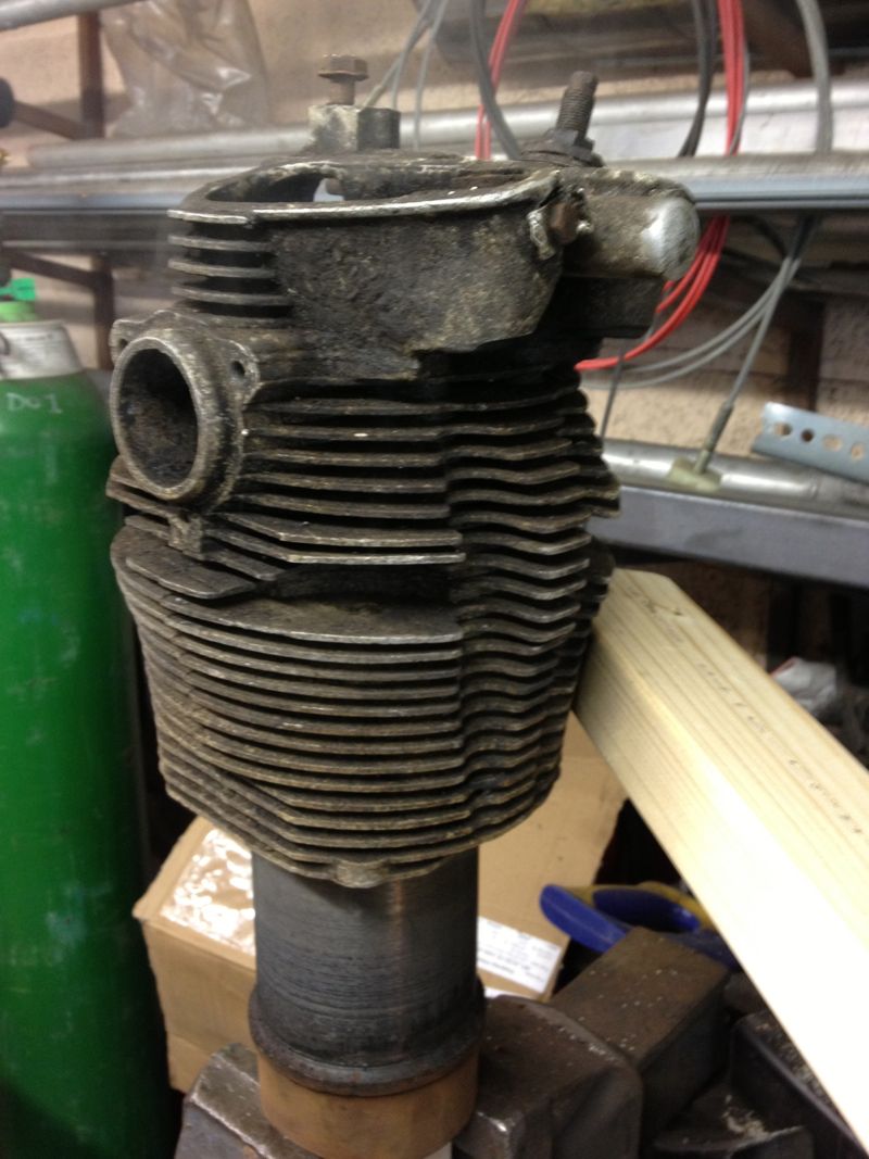
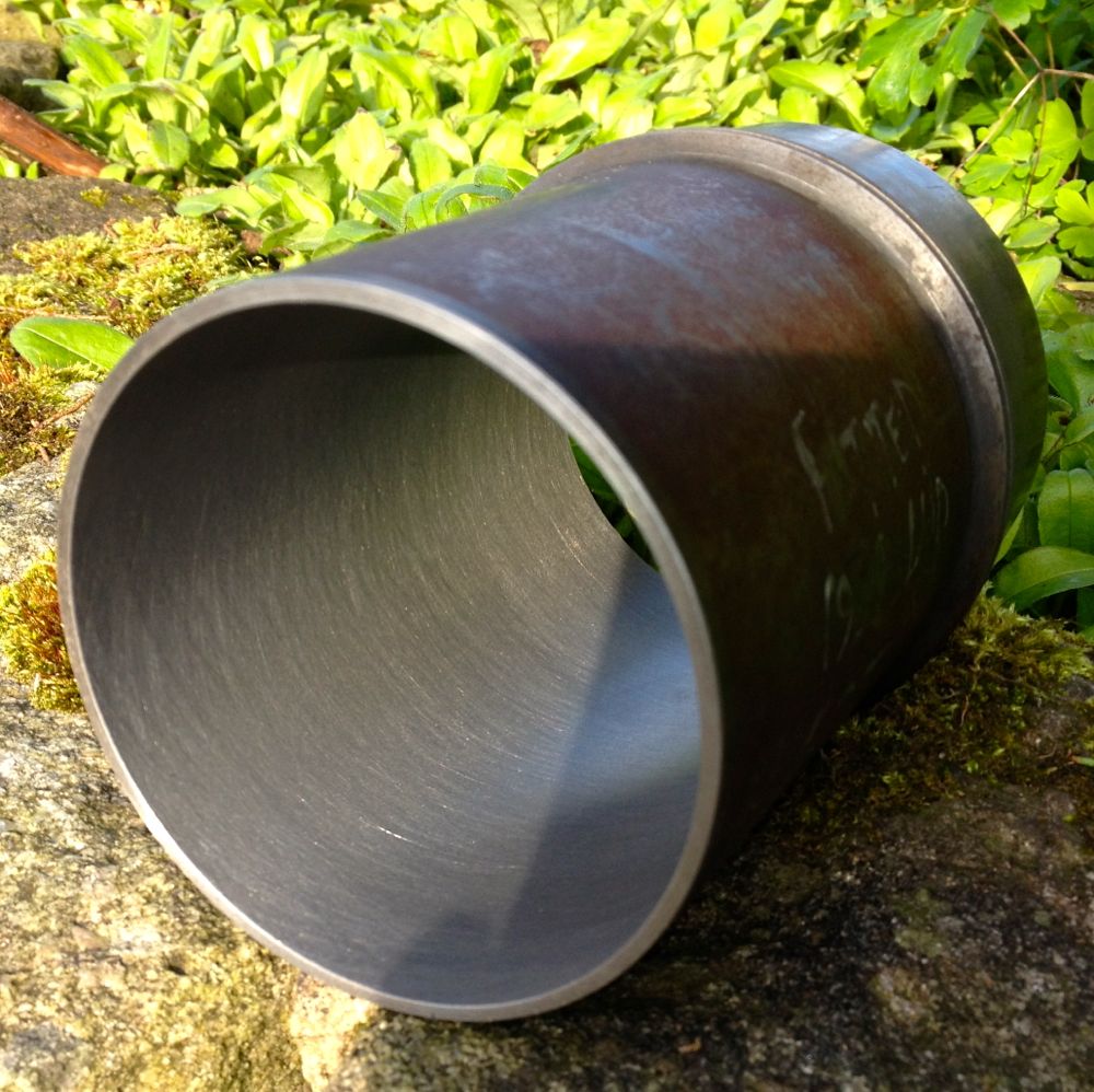
As usual I have been working away, and work has been taking all my time, but today I collected some test cylinders from John Passfield. These were early Dyna ones, and I just needed the liners to machine.
First you have to get them out of the cylinders, Panhard suggests using a U shaped gas torch, but to be honest any large roofing torch, or an electric fan oven will do it. The latter is a no no if it is in the house, as the old oils etc leave a nice odour that Febreze won’t shift!
So after placing the cylinder on a lump of wood, clamped to a vice, using a large soft flame aim for the area around the finning where the nuts go onto the crankcase studs ( the metal is thickest around here), and keep moving the flame around the cylinder to spread the heat evenly.
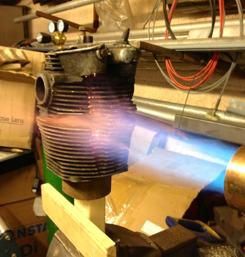
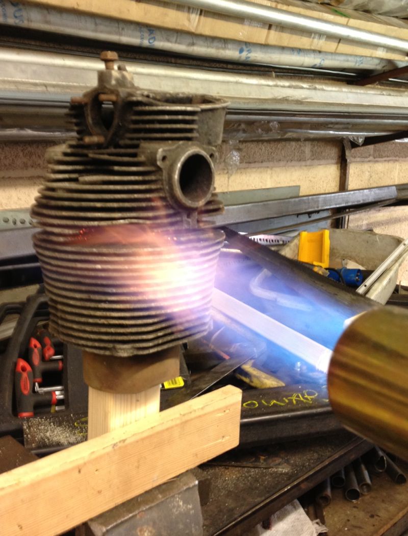
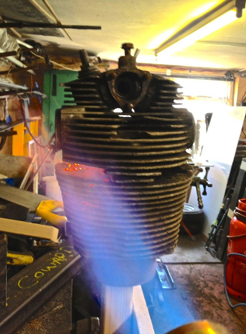
After a minute or so, the liner will drop partially and that’s why I have a piece of wood below, for it to land on. In realty it doesn’t drop to far, as the liner tends to stick to the wood, but if you tap the cylinder, it will drop clear of the aluminium cylinder.
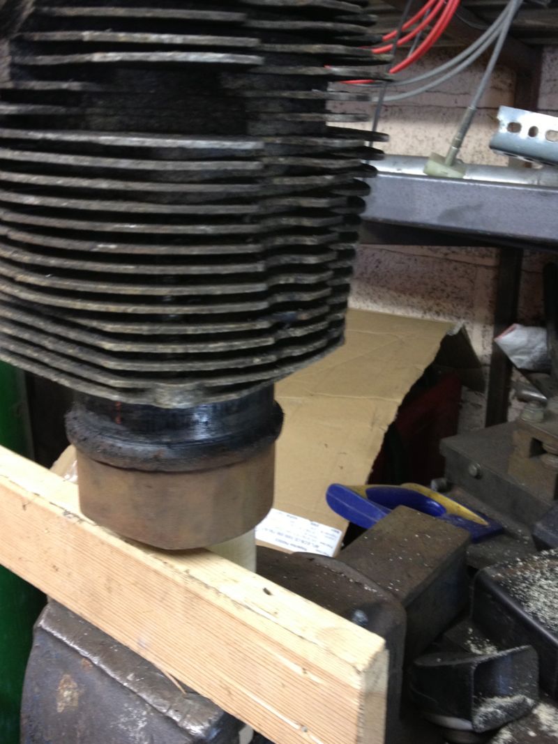
Easy really, but they will be VERY hot, so be careful and wear a heatproof glove, and let them cool naturally, which was easy today, as it was 2ºC outside.
First you have to get them out of the cylinders, Panhard suggests using a U shaped gas torch, but to be honest any large roofing torch, or an electric fan oven will do it. The latter is a no no if it is in the house, as the old oils etc leave a nice odour that Febreze won’t shift!
So after placing the cylinder on a lump of wood, clamped to a vice, using a large soft flame aim for the area around the finning where the nuts go onto the crankcase studs ( the metal is thickest around here), and keep moving the flame around the cylinder to spread the heat evenly.
After a minute or so, the liner will drop partially and that’s why I have a piece of wood below, for it to land on. In realty it doesn’t drop to far, as the liner tends to stick to the wood, but if you tap the cylinder, it will drop clear of the aluminium cylinder.
Easy really, but they will be VERY hot, so be careful and wear a heatproof glove, and let them cool naturally, which was easy today, as it was 2ºC outside.
Panhard Cylinder Liner Rebore Update 4
13/10/12 19:00 Filed in: Panhard Piston | Whatton
One of the areas I had to improve was the direct reading of the Whatton Boring Bar now that I have converted it to some readily available indexable tooltips.
The dedicated micrometer was not touching the tooltip, because the tooltip was lower than the anvil. A few moments on the lathe to test the idea, and bingo.
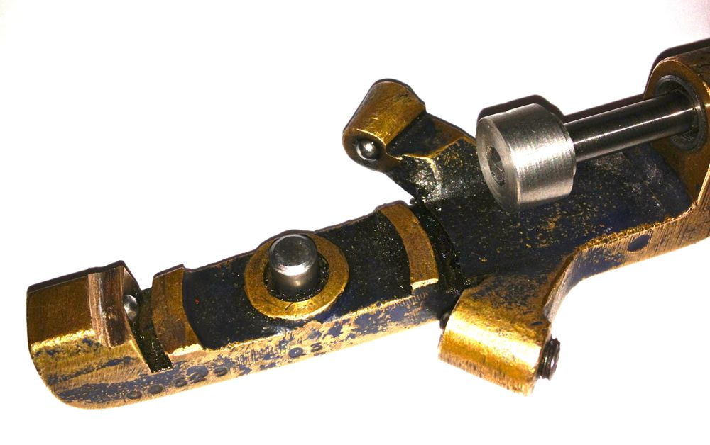
Here it is in situ, that’s attached to the anvil, with the micrometer fixed to the boring bar.
I just have to set the tip position and to do another test bore to establish the actual bore size measured by the three point bore micrometer versus the indicated reading of the Whatton micrometer.
The dedicated micrometer was not touching the tooltip, because the tooltip was lower than the anvil. A few moments on the lathe to test the idea, and bingo.
Here it is in situ, that’s attached to the anvil, with the micrometer fixed to the boring bar.
I just have to set the tip position and to do another test bore to establish the actual bore size measured by the three point bore micrometer versus the indicated reading of the Whatton micrometer.
Panhard Cylinder Liner Rebore Update 3
07/10/12 17:02 Filed in: Panhard Piston | Whatton
Yet again, I could only manage a few hours on the Panhard stuff, but I have finally cured the machining issues I had reboring the liners.
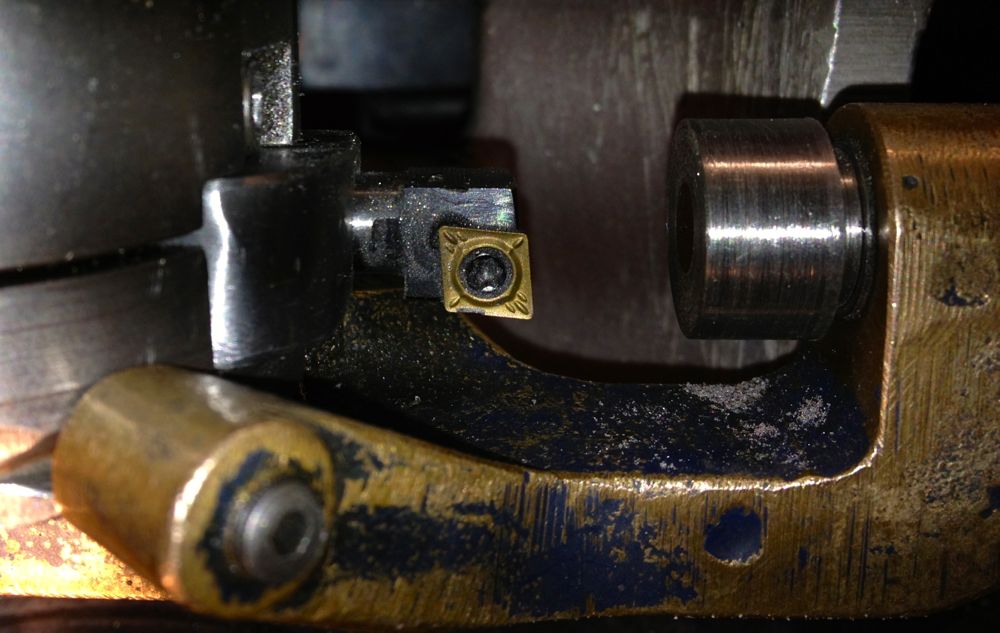
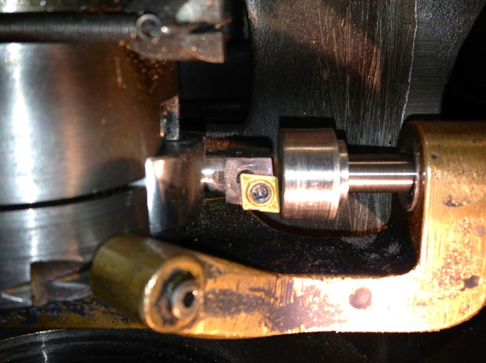
This is the set up as it stands now, long tooltip holder, modified LH boring bar with indexable CCMT insert, but unfortunately the longer tooltip holder fouls the boring bar micrometer body, so I cannot take a direct measurement using it at the moment. A little tweak with a Dremel should solve this, but I’ll do it another day, when I make a sleeve for the anvil, so it contacts the lower cutting surface of the new indexable insert.
On examination the bore was truly round, had a good consistent surface finish and measured 86.03 mm at the top, middle and bottom. I have eliminated the chatter that caused the rippling to the bore last weekend, by using the larger tooltip holder, but I got a slight scoring at three points afterwards. However, a slower feed speed, as well as tightening the spring loaded gibs, and increasing the pressure on the boring bar sleeves to eliminate the sliding play stopped any further occurrences.
Interestingly the original induction motor runs lot cooler with the vacuum pump motor coupling, which has a rubber cush drive rather than a leather or felt pad, and even with the increased loadings and therefore additional effort required to move the boring bar ,through the slides, there is no increase in temperature.
The ripple to the bores was caused by me inadvertently using the shorter tooltip holder, which is really made for the smaller bores sizes. The grub screw which is designed to lock the tooltip holder in position, was in fact gripping the adjusting plate, and so the tooltip holder was vibrating and moving on the screw adjuster.
Considering I didn’t have a manual, or know of any other person with one of these, losing just one liner to teething issues is a good result.
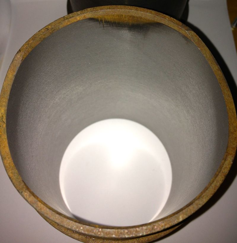
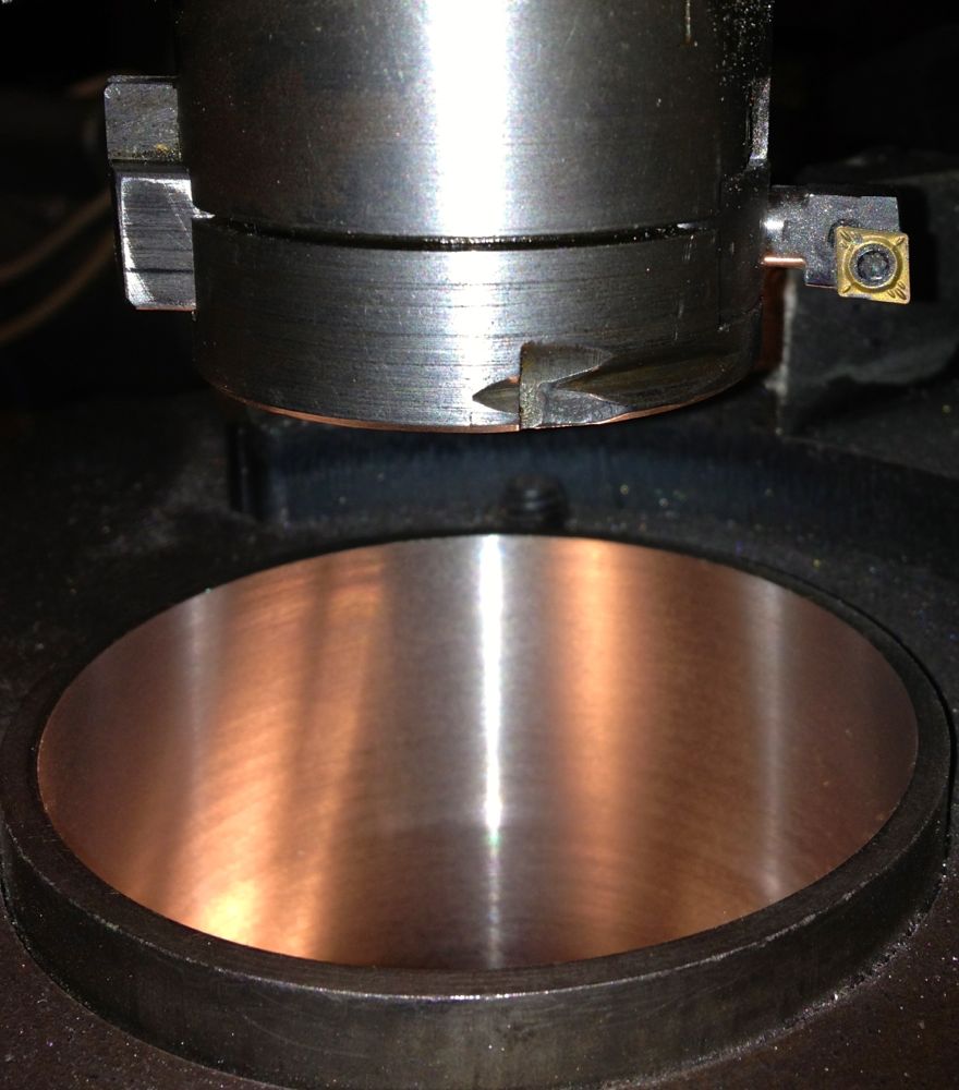
Here is the test cylinder after honing, but not washed yet though.
This is the set up as it stands now, long tooltip holder, modified LH boring bar with indexable CCMT insert, but unfortunately the longer tooltip holder fouls the boring bar micrometer body, so I cannot take a direct measurement using it at the moment. A little tweak with a Dremel should solve this, but I’ll do it another day, when I make a sleeve for the anvil, so it contacts the lower cutting surface of the new indexable insert.
On examination the bore was truly round, had a good consistent surface finish and measured 86.03 mm at the top, middle and bottom. I have eliminated the chatter that caused the rippling to the bore last weekend, by using the larger tooltip holder, but I got a slight scoring at three points afterwards. However, a slower feed speed, as well as tightening the spring loaded gibs, and increasing the pressure on the boring bar sleeves to eliminate the sliding play stopped any further occurrences.
Interestingly the original induction motor runs lot cooler with the vacuum pump motor coupling, which has a rubber cush drive rather than a leather or felt pad, and even with the increased loadings and therefore additional effort required to move the boring bar ,through the slides, there is no increase in temperature.
The ripple to the bores was caused by me inadvertently using the shorter tooltip holder, which is really made for the smaller bores sizes. The grub screw which is designed to lock the tooltip holder in position, was in fact gripping the adjusting plate, and so the tooltip holder was vibrating and moving on the screw adjuster.
Considering I didn’t have a manual, or know of any other person with one of these, losing just one liner to teething issues is a good result.
Here is the test cylinder after honing, but not washed yet though.
