Mar 2013
Panhard Exhaust Valve Insert & Guide Replacement
31/03/13 20:02 Filed in: Panhard Engine
I have to say without doubt, this is the single most awkward task I have tackled on a Panhard engine. Valve guide removal on a 50 year old engine is not for the fainthearted, and even though copious amounts of heat were used, the whole process requires levels of force that make you wince.
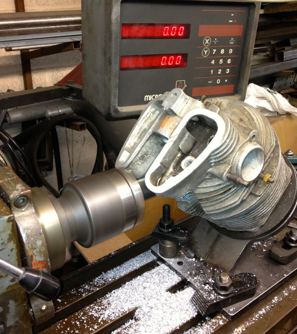
After making a suitable drift and warming the cylinder up, (spit just beads off), I inverted it onto my anvil!
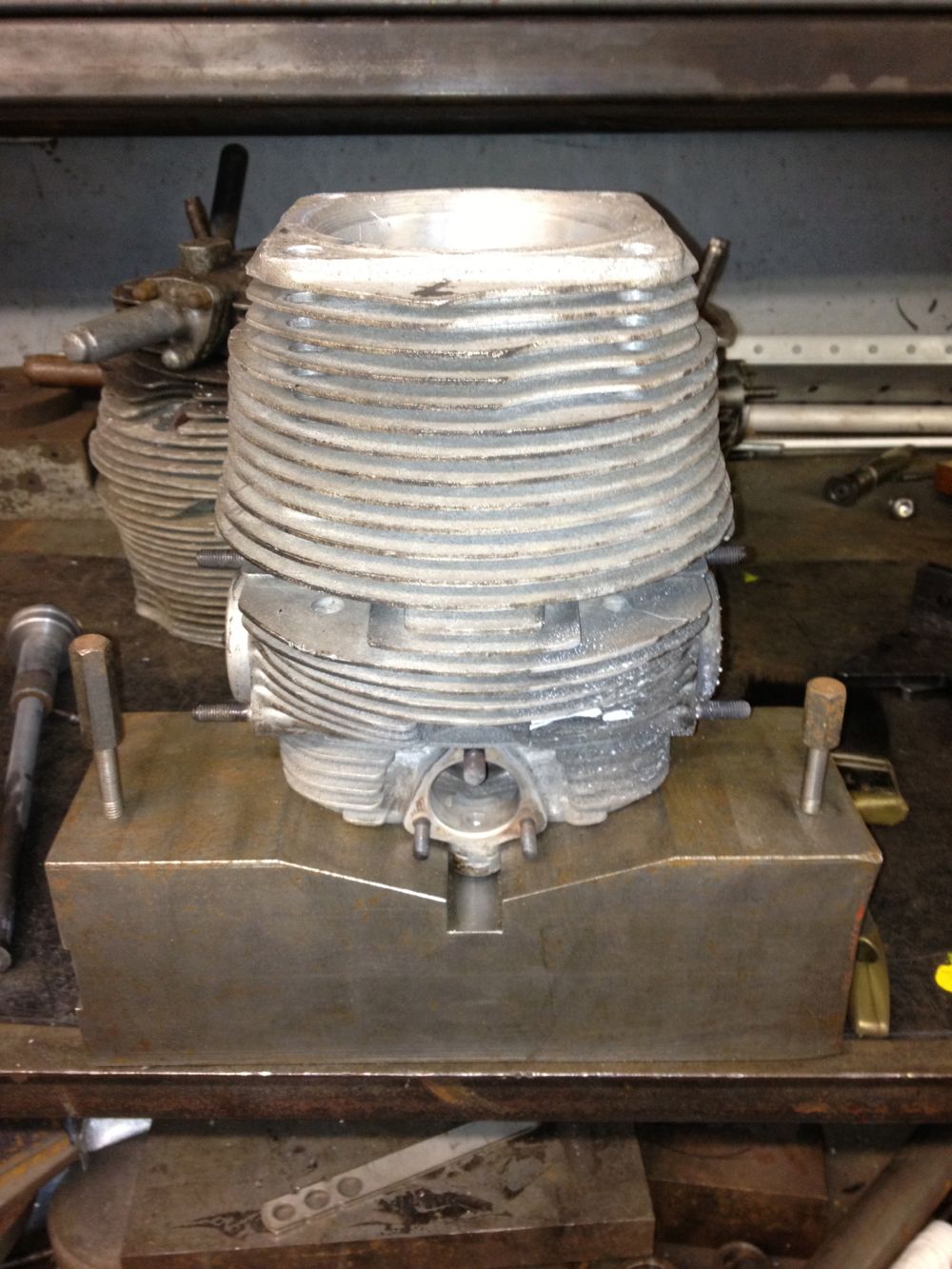
After a dozen blows, it started to move, by which time it was cooling, so I decided to drill the inner out some more and lose some of the interference fit. I then heated the cylinder up some more and inverted it quickly on the anvil ( the cotton towelling rag caught alight!), and hit the guide some more. Finally it eased out and the cylinder looked like this.
The seat had been removed previously.
Now the task of refitting the guide, I decide this was first up as the smaller diameter required more heat to open up, so my thinking was do this first, then top up the heat and tackle the insert.I successfully managed this, but it was a two stage process, because even though the guide was -17ºC, it soon warmed when in contact with the cylinder head and it needed a reheat to ease it into the head. I also made a specially turned up brass drift, so as not to damage the new guide.
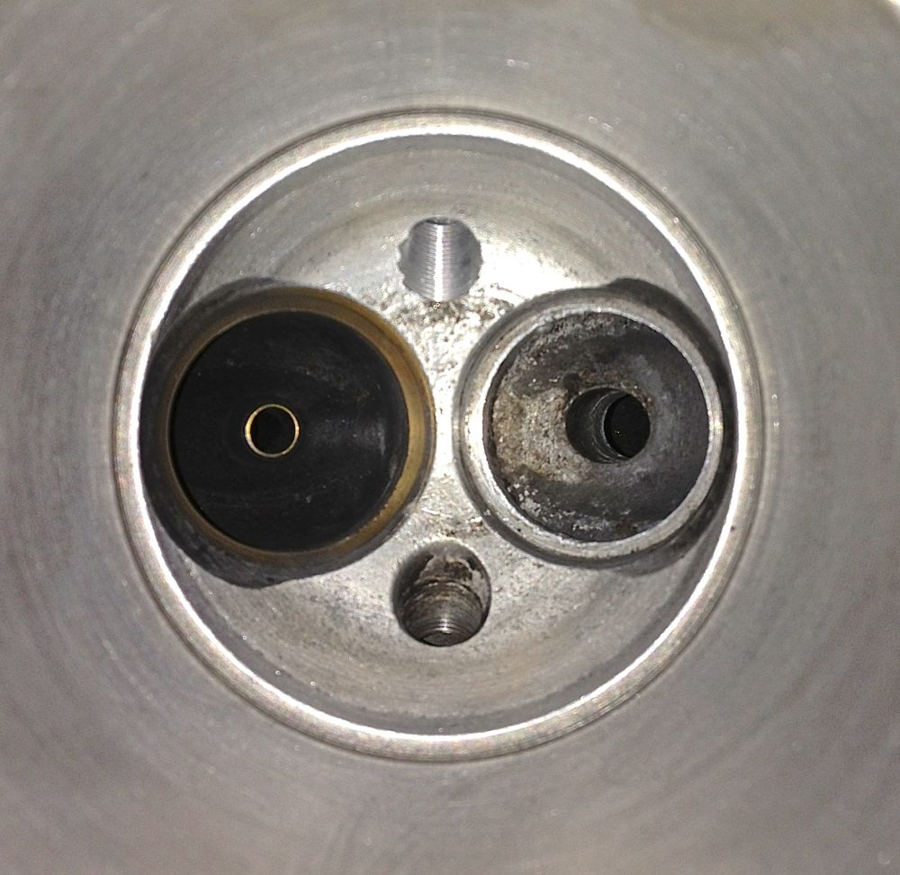
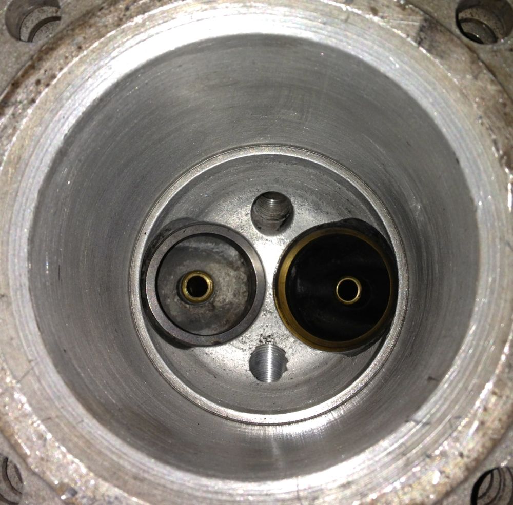
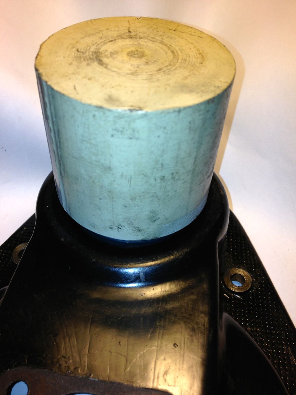
Anyway, I next did the insert and here it is just installed, blueing on the heat transfer from the cylinder! You can see the new guide too.
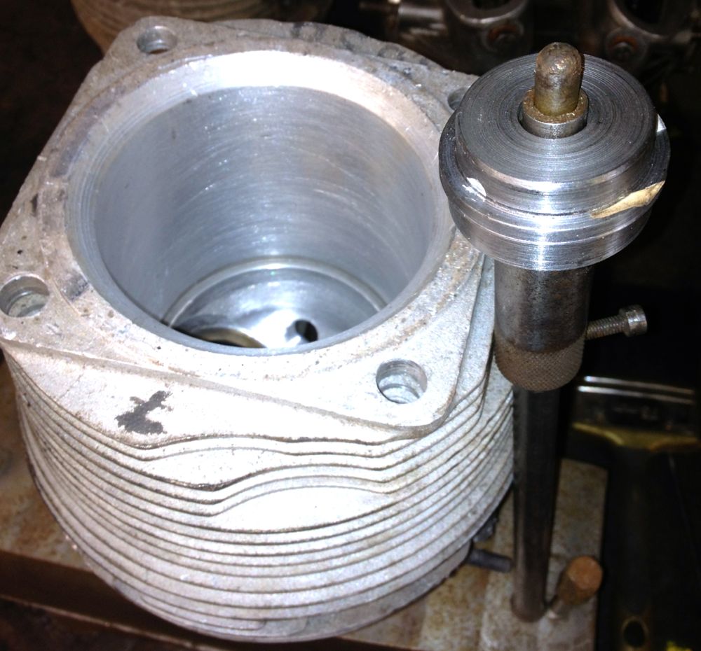
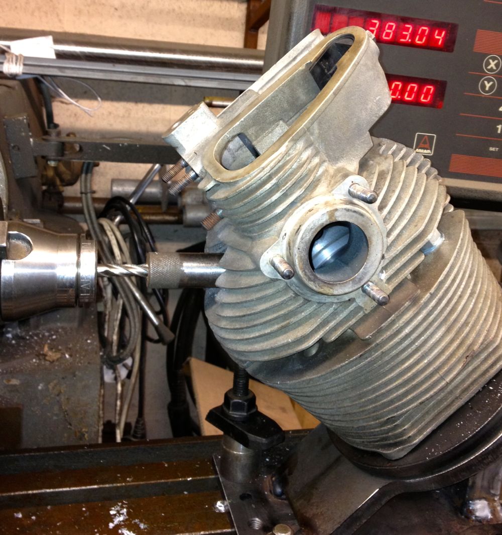
All this was possible by modifying my seat installation tool, shown below, complete with burnt paper! This is the interference fit, so you can extract the installation tool, as the seat insert shrinks. It was wonderful to watch as the cold insert heated up from outside to middle as it absorbed the heat, proof that there is a heat transfer path at this point.
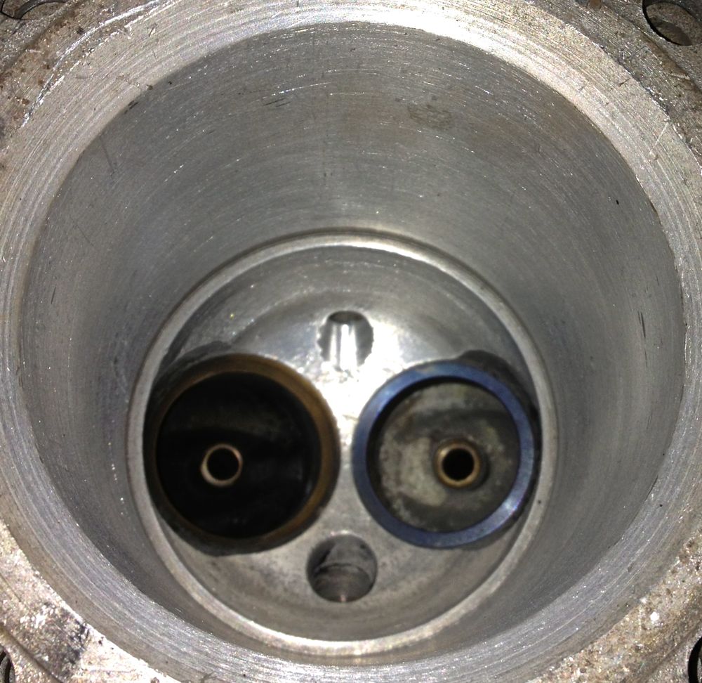
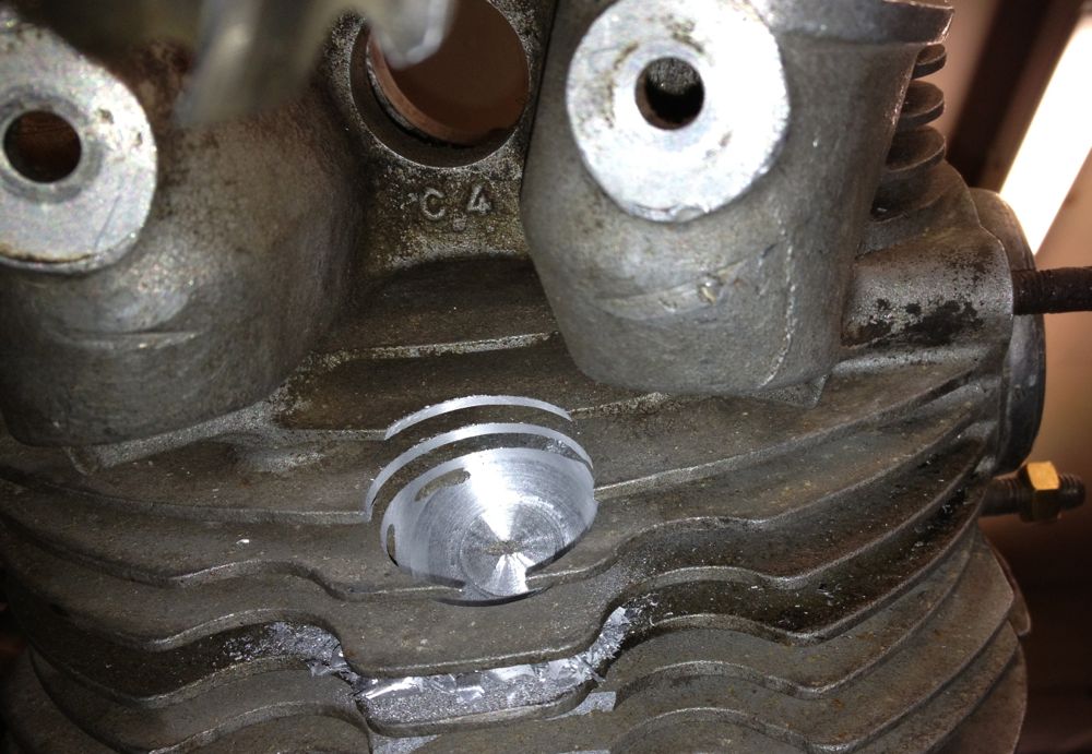
Here is the cooler result about half an hour later, so I just need to recut the valve seat, to finish, but that’s for another day.
Definitely not for the faint hearted, and as a result I am going to make some new valve guides next time and re-machine the cylinders each time I do this in the future.
After making a suitable drift and warming the cylinder up, (spit just beads off), I inverted it onto my anvil!
After a dozen blows, it started to move, by which time it was cooling, so I decided to drill the inner out some more and lose some of the interference fit. I then heated the cylinder up some more and inverted it quickly on the anvil ( the cotton towelling rag caught alight!), and hit the guide some more. Finally it eased out and the cylinder looked like this.
The seat had been removed previously.
Now the task of refitting the guide, I decide this was first up as the smaller diameter required more heat to open up, so my thinking was do this first, then top up the heat and tackle the insert.I successfully managed this, but it was a two stage process, because even though the guide was -17ºC, it soon warmed when in contact with the cylinder head and it needed a reheat to ease it into the head. I also made a specially turned up brass drift, so as not to damage the new guide.
Anyway, I next did the insert and here it is just installed, blueing on the heat transfer from the cylinder! You can see the new guide too.
All this was possible by modifying my seat installation tool, shown below, complete with burnt paper! This is the interference fit, so you can extract the installation tool, as the seat insert shrinks. It was wonderful to watch as the cold insert heated up from outside to middle as it absorbed the heat, proof that there is a heat transfer path at this point.
Here is the cooler result about half an hour later, so I just need to recut the valve seat, to finish, but that’s for another day.
Definitely not for the faint hearted, and as a result I am going to make some new valve guides next time and re-machine the cylinders each time I do this in the future.
Comments
Panhard Twin Plugging Cylinders 2
30/03/13 19:31 Filed in: Panhard Engine
Another day, another dollar, and as Jean Paul Cesar suggested, putting the milling head horizontal was the easiest solution to my limited vertical height, but if the jig had been shorter, it wouldn’t have worked because the locking bar would have fouled the milling table. 
Here’s the mill is centred on the OEM spark plug horizontally now. The Elliott Sturdimill is a really flexible piece of kit, and I didn’t realise the mill table could go so high, but to be honest I have never used it like this, and it turned out to be a master stroke, as I didn’t have to modify my jig.
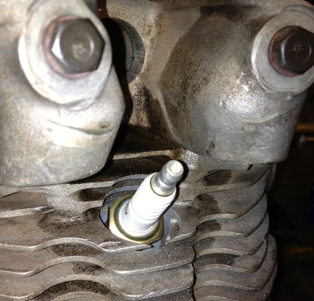
and the chamber side is impressively central too, but just need to rework the exposed threaded area to match the OEM detail
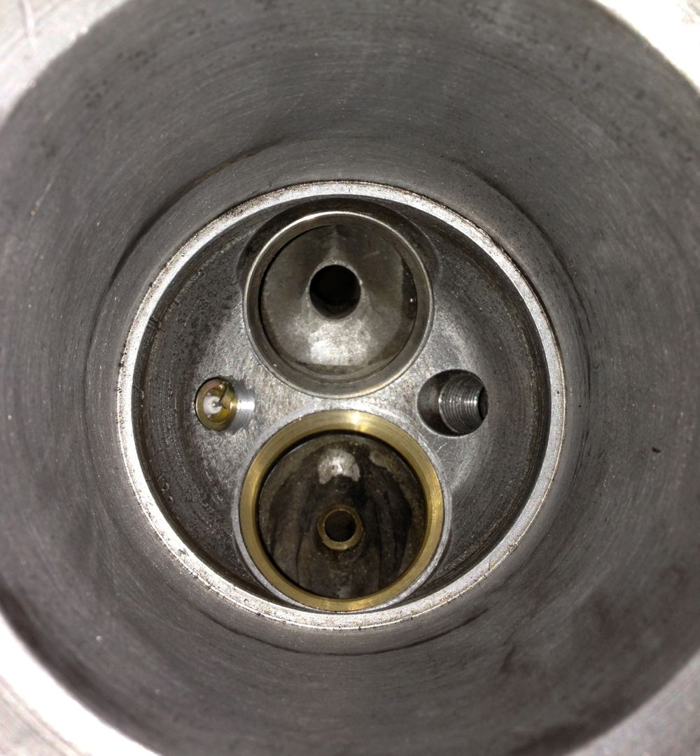
The depth of machining compares well with the OEM plug location.
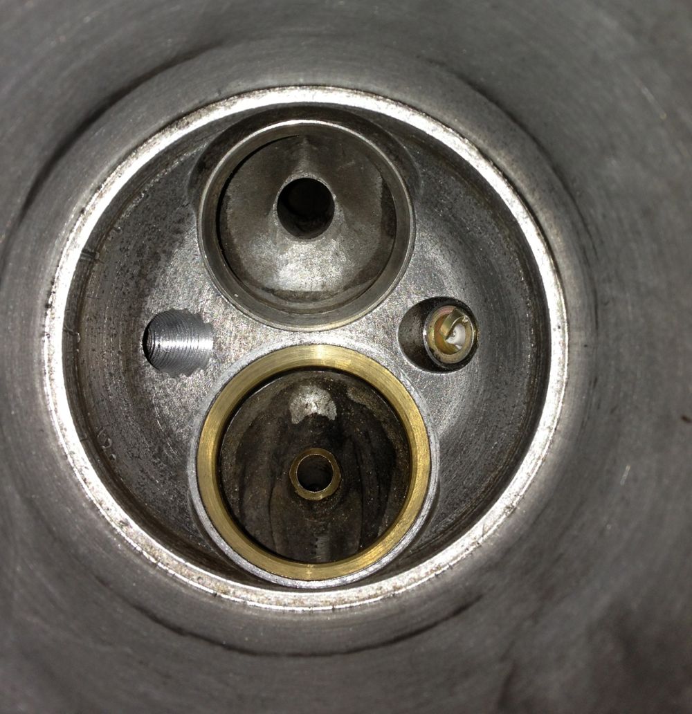
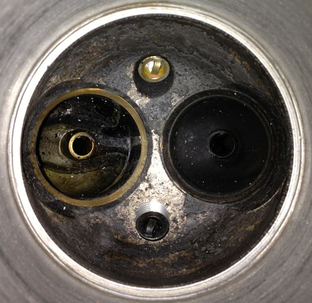
Brian’s other cylinder machined with two plugs in situ, a little more work to clean up the exposed threads and the job is finished.
Here’s the mill is centred on the OEM spark plug horizontally now. The Elliott Sturdimill is a really flexible piece of kit, and I didn’t realise the mill table could go so high, but to be honest I have never used it like this, and it turned out to be a master stroke, as I didn’t have to modify my jig.
and the chamber side is impressively central too, but just need to rework the exposed threaded area to match the OEM detail
The depth of machining compares well with the OEM plug location.
Brian’s other cylinder machined with two plugs in situ, a little more work to clean up the exposed threads and the job is finished.
Panhard Twin Plugging Cylinders 1
29/03/13 21:32 Filed in: Panhard Engine
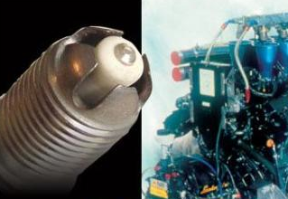
Twin plugging is adding another spark plug to each cylinder, so that each cylinder has two plugs. This is beneficial in a domed piston , domed combustion chamber environment, because the flame front can be chopped short by the lopsided combustion processes. To make sure this non ideal combustion is completed, it’s usual to run plenty of ignition advance, and as the rpm goes up this advance figure rises. High advance exposes the cylinder components to a longer heat exposure, so the engine runs hotter too.
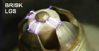
If you look at the Panhard combustion chambers you can see the spark plug angle is less than ideal, and there is evidence of electrode shielding too, so Brian’s engine will have surface
discharge spark plugs, which are at a disadvantage at low speed, & lean mixtures, so fitting an extra spark plug will negate some of this.
How do you twin plug a cylinder?
You’ll need access to a milling machine ideally, worst case a pillar drill and a Dremel. Sequence of events are,
1. Establish existing spark plug position.
2. rotate cylinder 180º.
3. Drill, tap & mill the spark plug recess.
4. Mill the fins to allow for spanner access.
Here is the start of my jig, which was some reused components from the crankshaft rig, and the honing clamp parts.
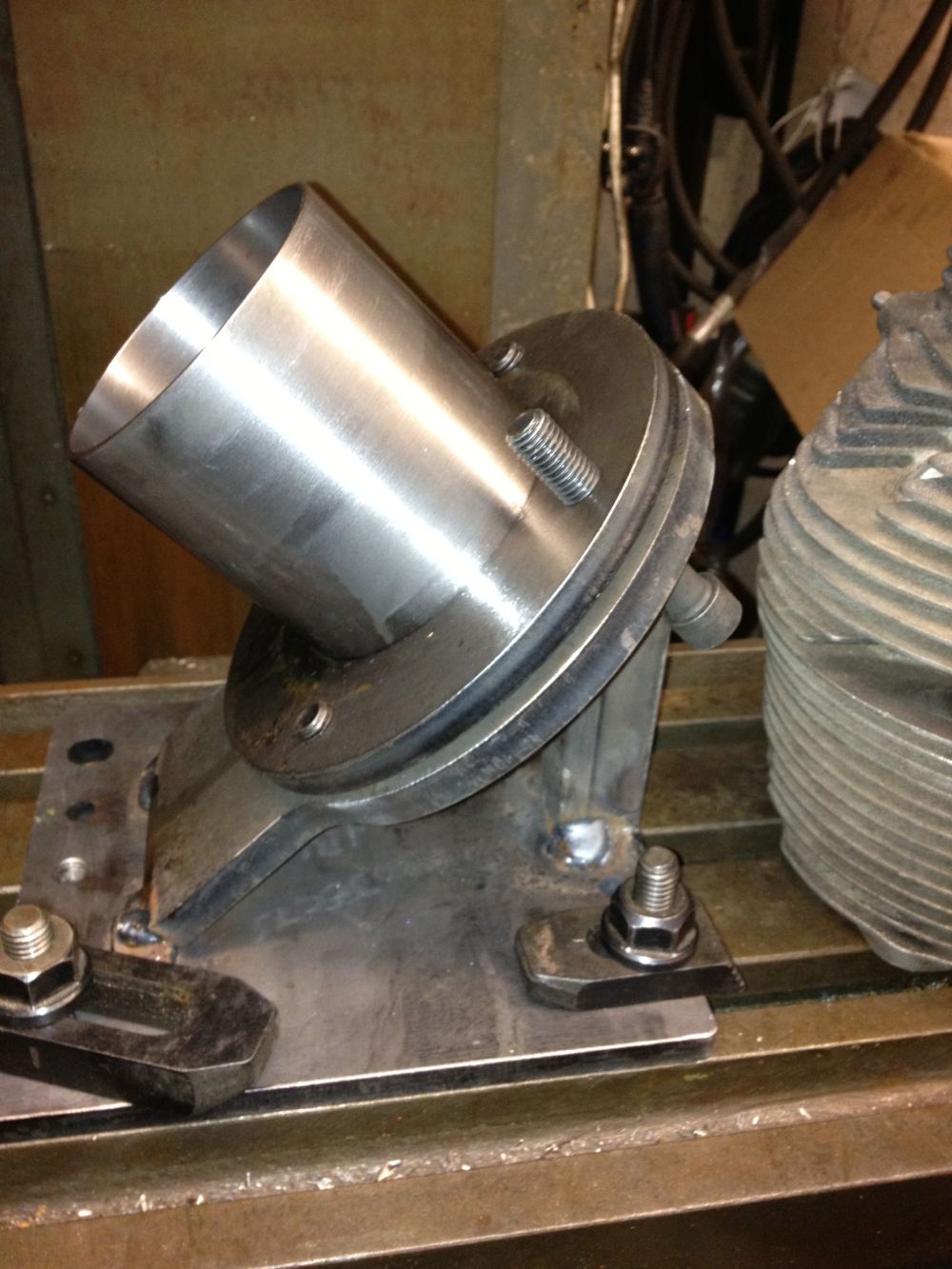
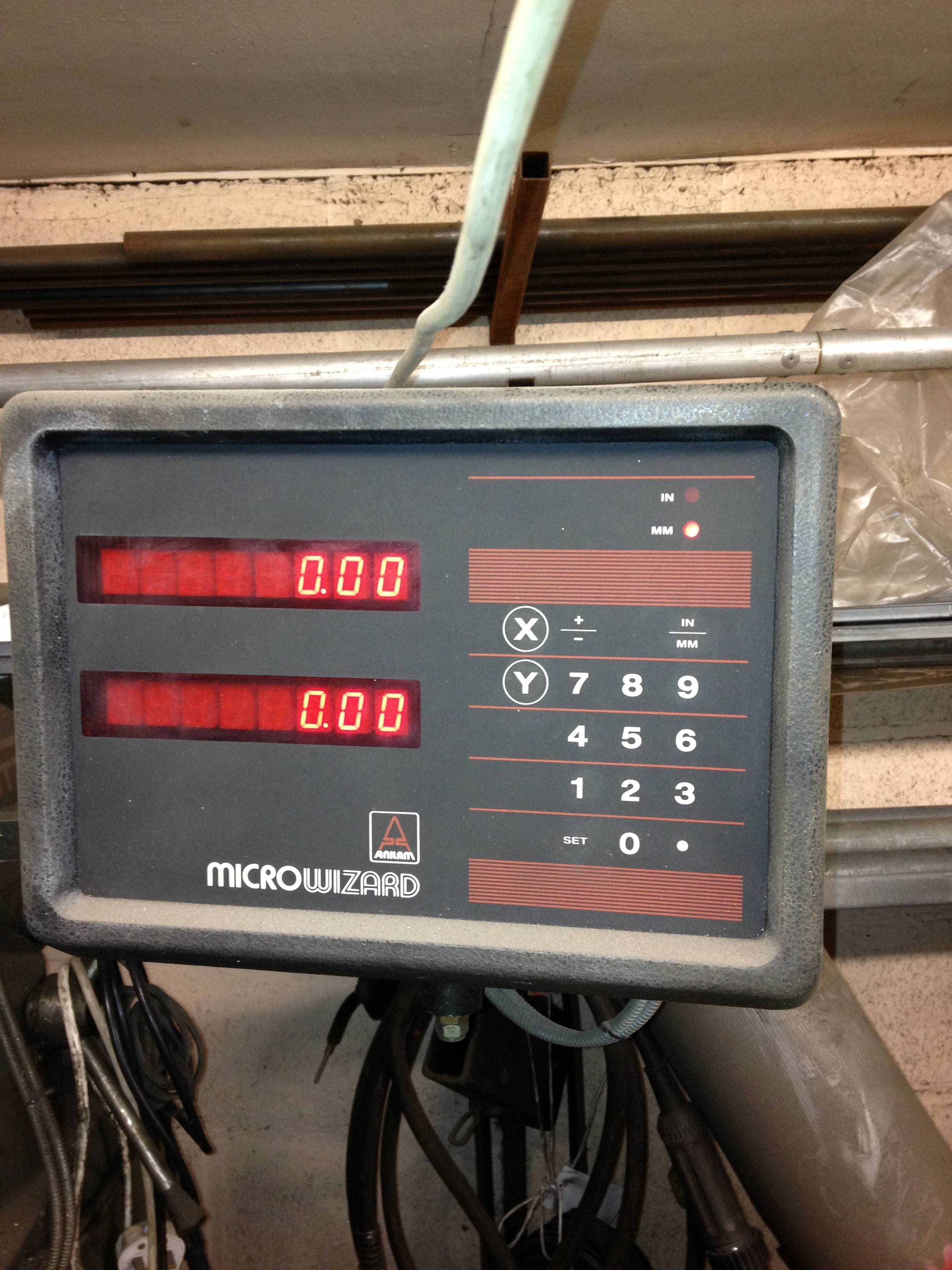
Checking everything is vertical and aligned
The cylinder is slid onto a turned down liner, and clamped in situ. Then we locate the centre of the original spark plug.
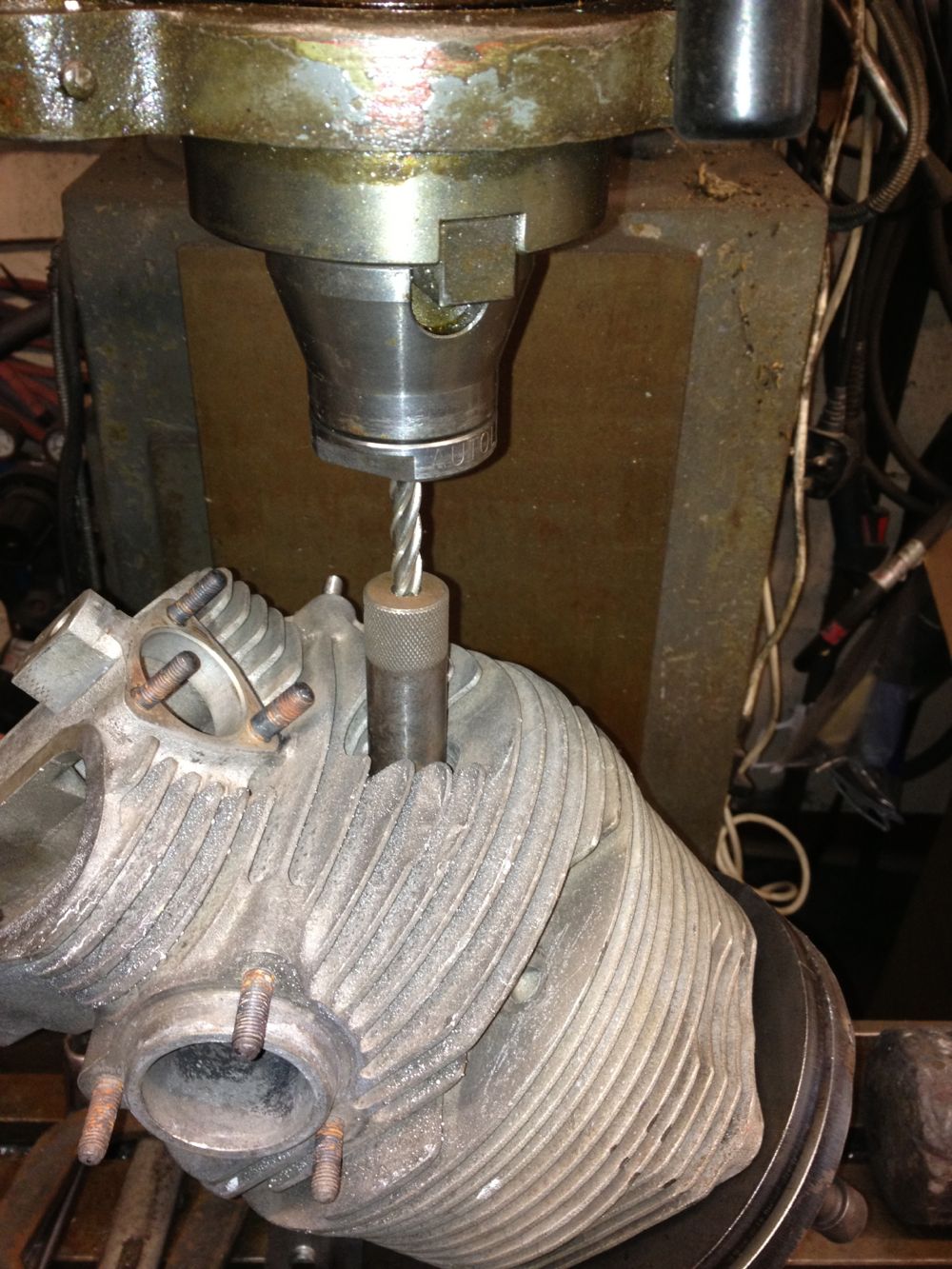
You have to watch you have enough clearance, and in my case I didn’t have enough height to use the larger milling cutters and associated collets. This mill uses Clarkson screwed shank milling tools, so I needed some long series ones for this kind of work. Unfortunately the first operation is to drill the spark plug hole, actually it isn’t, because i used a 20mm diameter slot drill to remove the fins and create a flat surface for a stock 118º HSS twist drill. When I wound the mill table fully down I couldn’t fit the larger INT 40 collet chuck, so I am looking at shortening the jig, angling the head at 45º, or better still, as fellow Panhardista Jean Paul Cesar suggested ”put the milling head horizontal”.
The latter idea is quite appealing, but that’s assuming the mill table can go high enough, and I’ll have to remove the boring bar from the other end of the mill table. I will know for sure tomorrow, and as I don’t have a surface block to place the jig on and hold it down, I might end up cutting the jig down yet, as I thought previously.
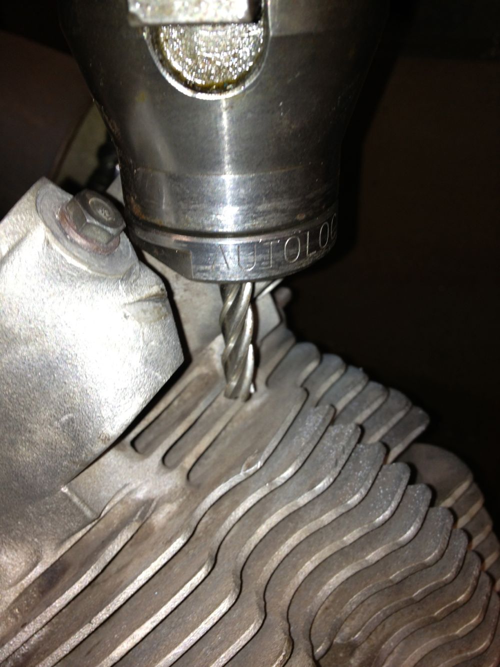
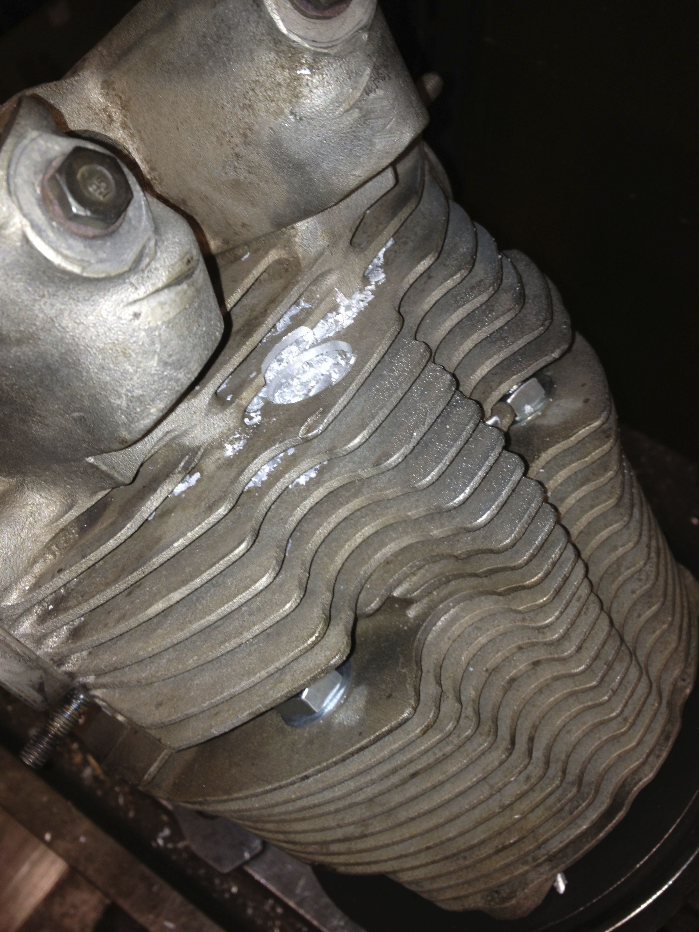
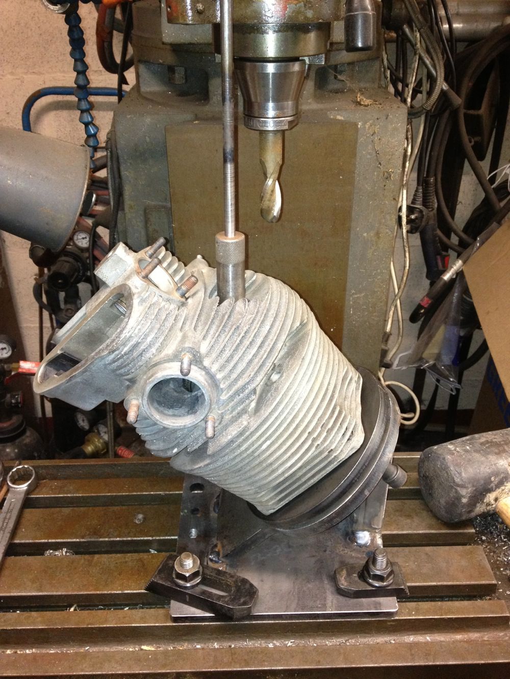
I still managed to do a little bit, here is the cylinder after the 20mm slot drill has cut through the fins, whilst the cylinder awaits the Ø12.5 tapping drill (for the M14 x 1.50 spark plug thread).
If you look at the Panhard combustion chambers you can see the spark plug angle is less than ideal, and there is evidence of electrode shielding too, so Brian’s engine will have surface
discharge spark plugs, which are at a disadvantage at low speed, & lean mixtures, so fitting an extra spark plug will negate some of this.
How do you twin plug a cylinder?
You’ll need access to a milling machine ideally, worst case a pillar drill and a Dremel. Sequence of events are,
1. Establish existing spark plug position.
2. rotate cylinder 180º.
3. Drill, tap & mill the spark plug recess.
4. Mill the fins to allow for spanner access.
Here is the start of my jig, which was some reused components from the crankshaft rig, and the honing clamp parts.
Checking everything is vertical and aligned
The cylinder is slid onto a turned down liner, and clamped in situ. Then we locate the centre of the original spark plug.
You have to watch you have enough clearance, and in my case I didn’t have enough height to use the larger milling cutters and associated collets. This mill uses Clarkson screwed shank milling tools, so I needed some long series ones for this kind of work. Unfortunately the first operation is to drill the spark plug hole, actually it isn’t, because i used a 20mm diameter slot drill to remove the fins and create a flat surface for a stock 118º HSS twist drill. When I wound the mill table fully down I couldn’t fit the larger INT 40 collet chuck, so I am looking at shortening the jig, angling the head at 45º, or better still, as fellow Panhardista Jean Paul Cesar suggested ”put the milling head horizontal”.
The latter idea is quite appealing, but that’s assuming the mill table can go high enough, and I’ll have to remove the boring bar from the other end of the mill table. I will know for sure tomorrow, and as I don’t have a surface block to place the jig on and hold it down, I might end up cutting the jig down yet, as I thought previously.
I still managed to do a little bit, here is the cylinder after the 20mm slot drill has cut through the fins, whilst the cylinder awaits the Ø12.5 tapping drill (for the M14 x 1.50 spark plug thread).
Panhard Front Timing Cover Modifications 2
19/03/13 16:45 Filed in: Panhard Engine
I just got word today the ignition has been despatched from the supplier, so in a few days it should arrive. I have decided to update the 3D model to incorporate the BMW camshaft sensors, so I could explore different possible locations, and this is the result so far. Looks like I might be making a tweak to the cover again, but this would only be if others were interested. The first batch will be as is shown below, as it will delay the item for Brian’s engine too much.
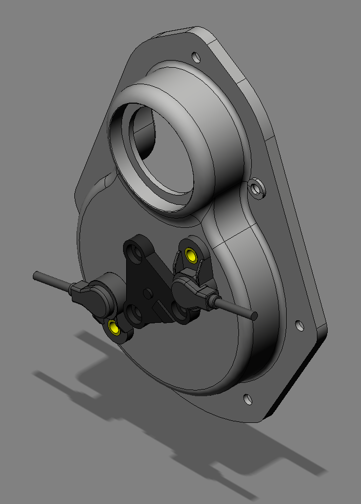
Internal space model, to check how much room is available. This is the sequential ignition variant with a fibre camshaft gear wheel.
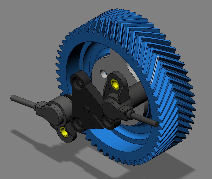
Internal space model, to check how much room is available. This is the sequential ignition variant with a fibre camshaft gear wheel.
Panhard Front Timing Cover Modification 1
18/03/13 18:27 Filed in: Panhard Engine
I have decided to fit electronic ignition to Brian’s engine, and although I can do it a few ways, and have done so in the past, I thought I’d raise the bar a little for Brian’s lump. As I don’t know where the advance curve will want to be, and I didn’t fancy a manual advance & retard system, that could get out of range with disastrous results inadvertently by persons unnamed, it was decided to fit programmable ignition that could cater for twin spark, as well as wasted spark aka Citröen 2CV.
I have identified an ignition system that I could use, that allowed adjustments via a laptop on the fly, which means as you are driving along, unlike TuneECU & my brother’s KTM, but that’s another story. Anyway, after looking at the ignition system some more and exploring how I could build it in neatly to the existing engine, I decided that the front cover was the best choice for my future plans. I need a cam sensor, and I have looked at using the pushrods, the rocker arms and a proximity sensor, but it was all too complicated. I modified Brian’s front cover to take a modern oil seal, and was going to start making a pulley based trigger wheel like I drew some time ago. However the cost of these parts outweighed their usefulness, so I decided Ito revisit the cover again. A couple of hours later, I had a 3D model, based on the dimensions of the original pressed cover,, that had the flexibility to accept any manner of different tooth triggering systems, and a front crankshaft seal that could cater for all ranges of front pulley mods others have done.
A few hiccups, later, one revision to cope with the planned programmable ignition unit, another because of the cost of the sensor loom, meant I’m on the third & hopefully final iteration of the new front cover. It should be more affordable, especially as I have got rid of those over priced Renault connectors. At the moment it is machined from billet, but there is a possibility I can use a casting, however this depends on numbers and whether it is economic to go this type of production process. because you still have to machine the casting, although you do save on roughing out the billet.
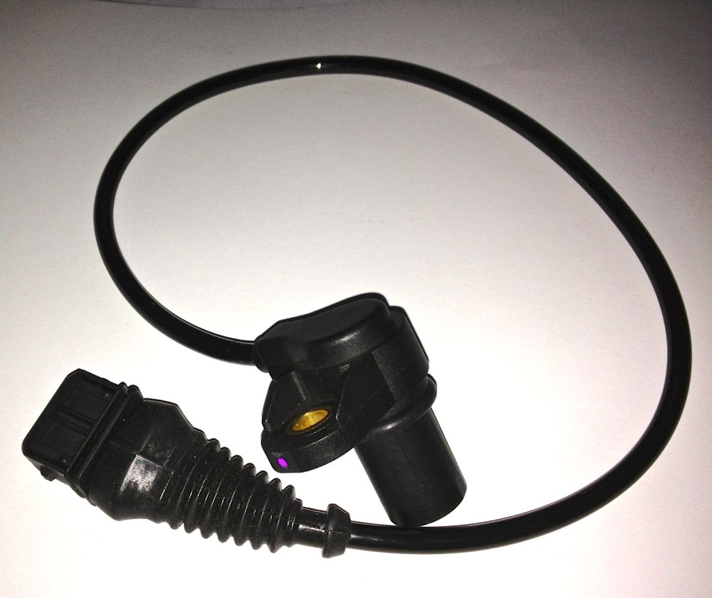
This is the sensor I will be using, which conveniently takes a readily available connector, that doesn’t require exotic crimpers. I have ordered another one for Brian’s engine, as this needs two.
I have identified an ignition system that I could use, that allowed adjustments via a laptop on the fly, which means as you are driving along, unlike TuneECU & my brother’s KTM, but that’s another story. Anyway, after looking at the ignition system some more and exploring how I could build it in neatly to the existing engine, I decided that the front cover was the best choice for my future plans. I need a cam sensor, and I have looked at using the pushrods, the rocker arms and a proximity sensor, but it was all too complicated. I modified Brian’s front cover to take a modern oil seal, and was going to start making a pulley based trigger wheel like I drew some time ago. However the cost of these parts outweighed their usefulness, so I decided Ito revisit the cover again. A couple of hours later, I had a 3D model, based on the dimensions of the original pressed cover,, that had the flexibility to accept any manner of different tooth triggering systems, and a front crankshaft seal that could cater for all ranges of front pulley mods others have done.
A few hiccups, later, one revision to cope with the planned programmable ignition unit, another because of the cost of the sensor loom, meant I’m on the third & hopefully final iteration of the new front cover. It should be more affordable, especially as I have got rid of those over priced Renault connectors. At the moment it is machined from billet, but there is a possibility I can use a casting, however this depends on numbers and whether it is economic to go this type of production process. because you still have to machine the casting, although you do save on roughing out the billet.
This is the sensor I will be using, which conveniently takes a readily available connector, that doesn’t require exotic crimpers. I have ordered another one for Brian’s engine, as this needs two.
Panhard Exhaust Valve Seat Musings
15/03/13 20:15 Filed in: Panhard Engine
This is the third time I have seen exhaust valve issues on Panhard engines. The first one was intermittent loose, the second one dropped out, and now this one in Brian’s engine which was damaged by valve seat recession.
Many years ago, I looked at a loose valve seat and wondered how if these things that were put in using cryogenics they could come loose, because it is rare in modern engines. I used a spreadsheet calculation to plot the relative sizes of the machined seat recess and the insert outside diameter as the temperature rose. Ultimately as the aluminium head gets hotter the dissimilar materials will expand, and loose their interference fit. It happened at around 320ºC, and the percussive action of the valve would almost certainly be moving the seat by then.
I have been told the expected temperature of the piston will be around 280ºC, but longer advance values from say, a tired distributor will mean the average head temperatures will almost certainly be higher. If you throw in a weak mixture to one cylinder being driven by a good one down the motorway on a hot day for example, and you’ll could easily meet this high temperature condition, but the valve runs much hotter at certain parts of the combustion cycle anyway.
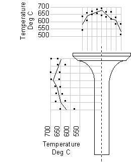
When combustion is initiated the exhaust valve head is heated on the face closest to the piston, and when it opens, the hot combustion products wrap around the valve head, heating the back of the valve head, the seat insert, and the stem. Whereas the inlet valve gets a cooling effect from the fresh charge, the exhaust relies on loosing this heat through the seat insert primarily, which can be as high as 75%. Typically the stem to guide takes the other 25%. These values can vary, depending on what you read, but the primary heat path is the valve seat insert to cylinder head interface. If this has poor conductivity, then the valve seat will not lose its heat, and run hot.
The other side of the coin is other air cooled engines and do they drop valve seats? I don’t know of a problem with Citröen 2CVs, but it was an occasional occurrence with 412 VWs, so perhaps it is the way of things to be. However, cooler oil, non weak mixtures, better ignition control and within specification valve guide clearances should all help reduce the temperatures that the valve seat is exposed to, but is there anything else that could be done.
A quick look into the history books, might reveal a few answers, and they do with exotic materials being used, valve gear exposed to airflow, excessive finning to lose heat, rich mixtures to create a cooling effect, and even reducing head diameter to reduce the surface area exposed to the combustion process. Anything else?
Here’s a Panhard valve seat insert, and below that is the same Panhard exhaust seat insert & a modern equivalent from a Harley Davidson…spot the difference? The clue is in the sides.
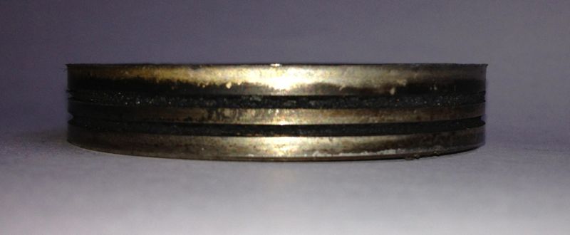
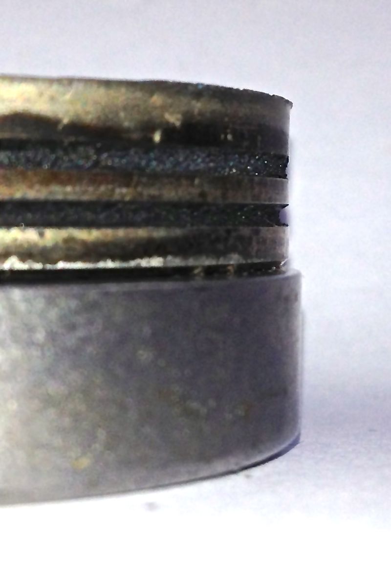
Notice the carbon deposits from the combustion products caking up the sides of the seat.
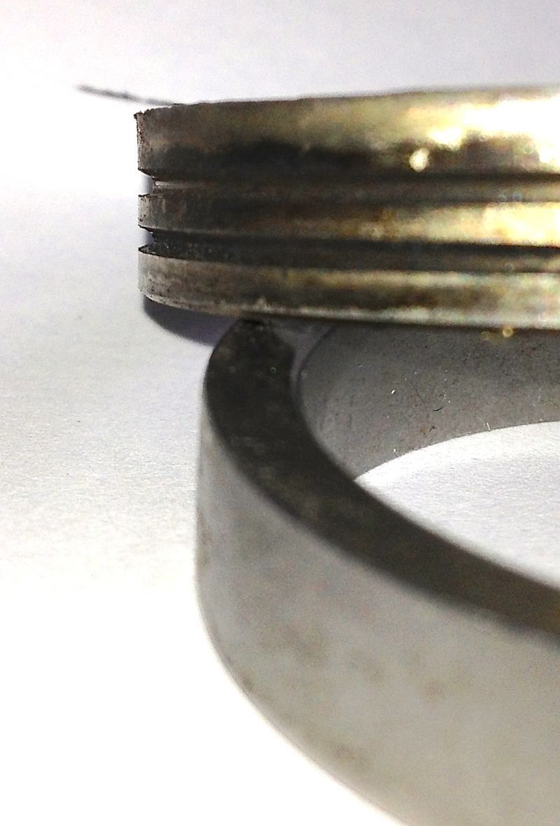
Panhard valve seat inserts, have peripheral grooves in them, nearly every other seat has smooth sides to maximise the contact area, so perhaps this explains the issue more than anything else. Panhard valve seats should be replaced with smooth bore equivalents, and possible have slightly more interference fit.
Brian’s engine will have this fitted to his affected cylinder.
Many years ago, I looked at a loose valve seat and wondered how if these things that were put in using cryogenics they could come loose, because it is rare in modern engines. I used a spreadsheet calculation to plot the relative sizes of the machined seat recess and the insert outside diameter as the temperature rose. Ultimately as the aluminium head gets hotter the dissimilar materials will expand, and loose their interference fit. It happened at around 320ºC, and the percussive action of the valve would almost certainly be moving the seat by then.
I have been told the expected temperature of the piston will be around 280ºC, but longer advance values from say, a tired distributor will mean the average head temperatures will almost certainly be higher. If you throw in a weak mixture to one cylinder being driven by a good one down the motorway on a hot day for example, and you’ll could easily meet this high temperature condition, but the valve runs much hotter at certain parts of the combustion cycle anyway.
When combustion is initiated the exhaust valve head is heated on the face closest to the piston, and when it opens, the hot combustion products wrap around the valve head, heating the back of the valve head, the seat insert, and the stem. Whereas the inlet valve gets a cooling effect from the fresh charge, the exhaust relies on loosing this heat through the seat insert primarily, which can be as high as 75%. Typically the stem to guide takes the other 25%. These values can vary, depending on what you read, but the primary heat path is the valve seat insert to cylinder head interface. If this has poor conductivity, then the valve seat will not lose its heat, and run hot.
The other side of the coin is other air cooled engines and do they drop valve seats? I don’t know of a problem with Citröen 2CVs, but it was an occasional occurrence with 412 VWs, so perhaps it is the way of things to be. However, cooler oil, non weak mixtures, better ignition control and within specification valve guide clearances should all help reduce the temperatures that the valve seat is exposed to, but is there anything else that could be done.
A quick look into the history books, might reveal a few answers, and they do with exotic materials being used, valve gear exposed to airflow, excessive finning to lose heat, rich mixtures to create a cooling effect, and even reducing head diameter to reduce the surface area exposed to the combustion process. Anything else?
Here’s a Panhard valve seat insert, and below that is the same Panhard exhaust seat insert & a modern equivalent from a Harley Davidson…spot the difference? The clue is in the sides.
Notice the carbon deposits from the combustion products caking up the sides of the seat.
Panhard valve seat inserts, have peripheral grooves in them, nearly every other seat has smooth sides to maximise the contact area, so perhaps this explains the issue more than anything else. Panhard valve seats should be replaced with smooth bore equivalents, and possible have slightly more interference fit.
Brian’s engine will have this fitted to his affected cylinder.
Panhard Front Oil Seal Modification
13/03/13 18:55 Filed in: Panhard Engine
I always intended to fit a modern oil seal to Brian’s engine, but I was going to make a new pulley arrangement, however the ignition has taken another direction lately, so I don’t need the crankshaft triggering I was going to use, but more about that one later.
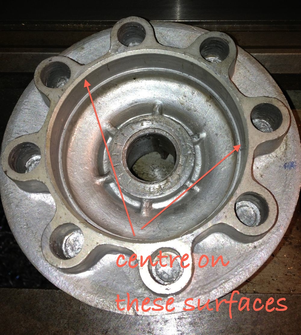
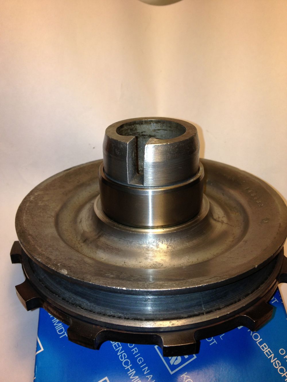
The original solution is to use a piston ring type seal
There is a groove in the front pulley (arrowed) to accept a piston ring type seal, with a hardened surface in the cover for it to rotate in.
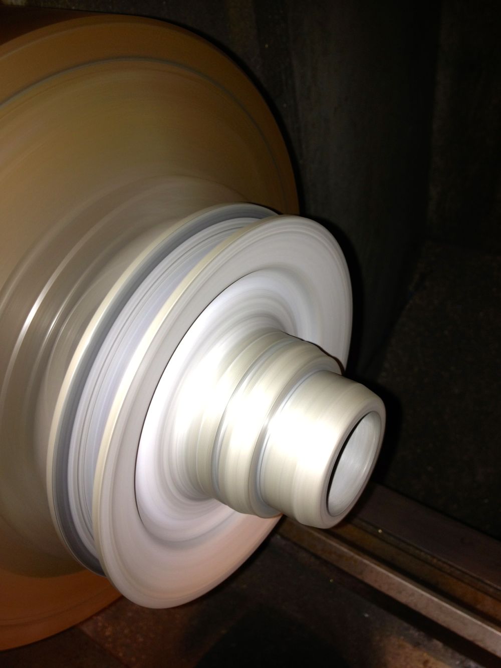
There are a few ways to create a seal here, the easiest at the moment is to do this. Place the front pulley in a lathe, aka damp Colchester
i
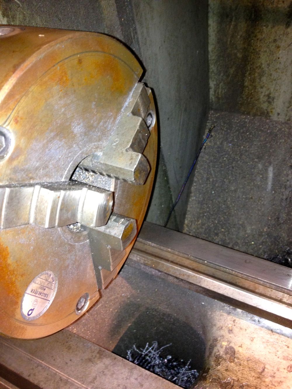
Check it’s running true, and machine to 40.02 mm, but don’t worry if you go too small as bearing retainer will save your bacon.
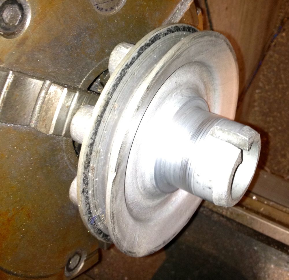
Install the 40 x 45 x 17 inner ring
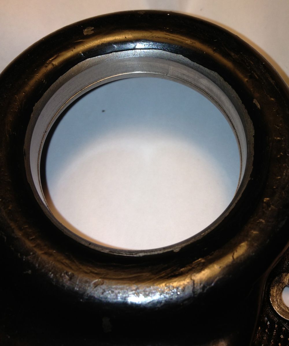
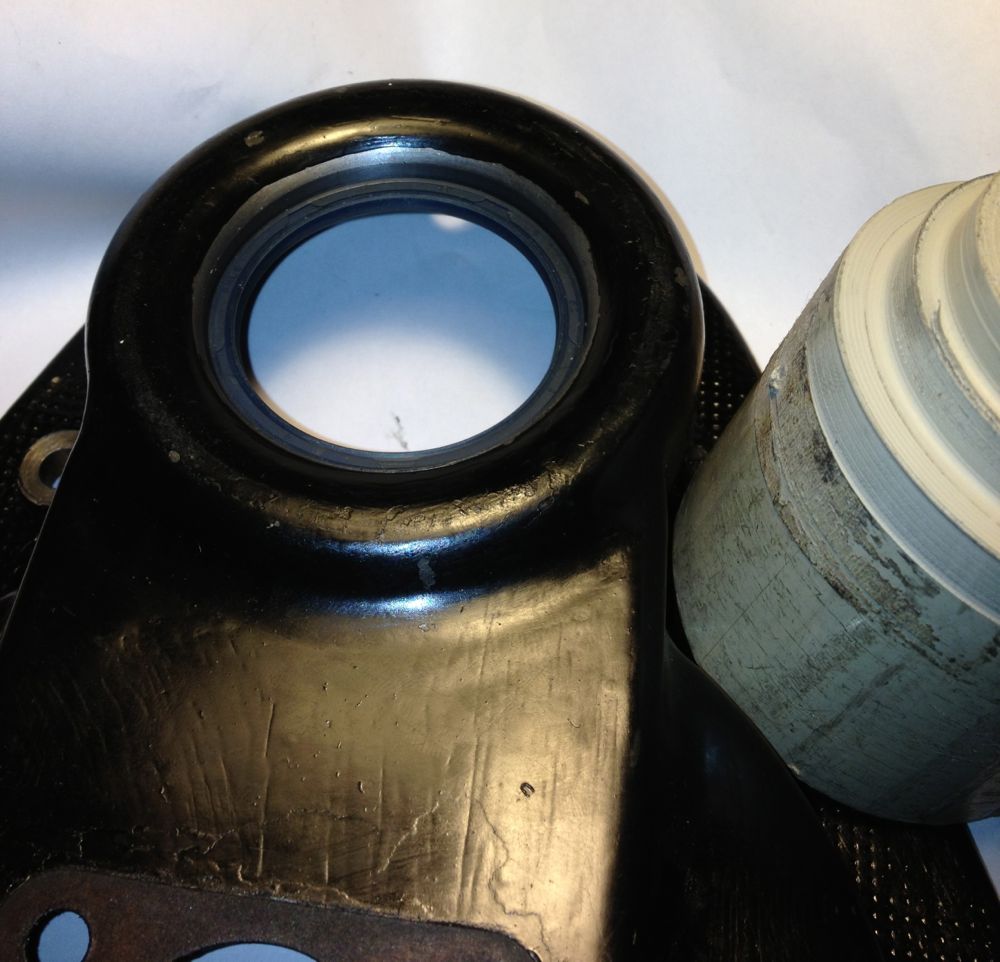
Next up modify the timing cover, I used a local engineering company to open up the hole to Ø52mm, the idea being I could use a 42 x 52 x 4, 5, 7 or 8 mm deep R23 oil seal. These are available in Viton in the smaller widths, but Nitrile or NBR is adequate for this diameter. The 5mm is shown, but I am changing this to the 8mm version when it arrives.
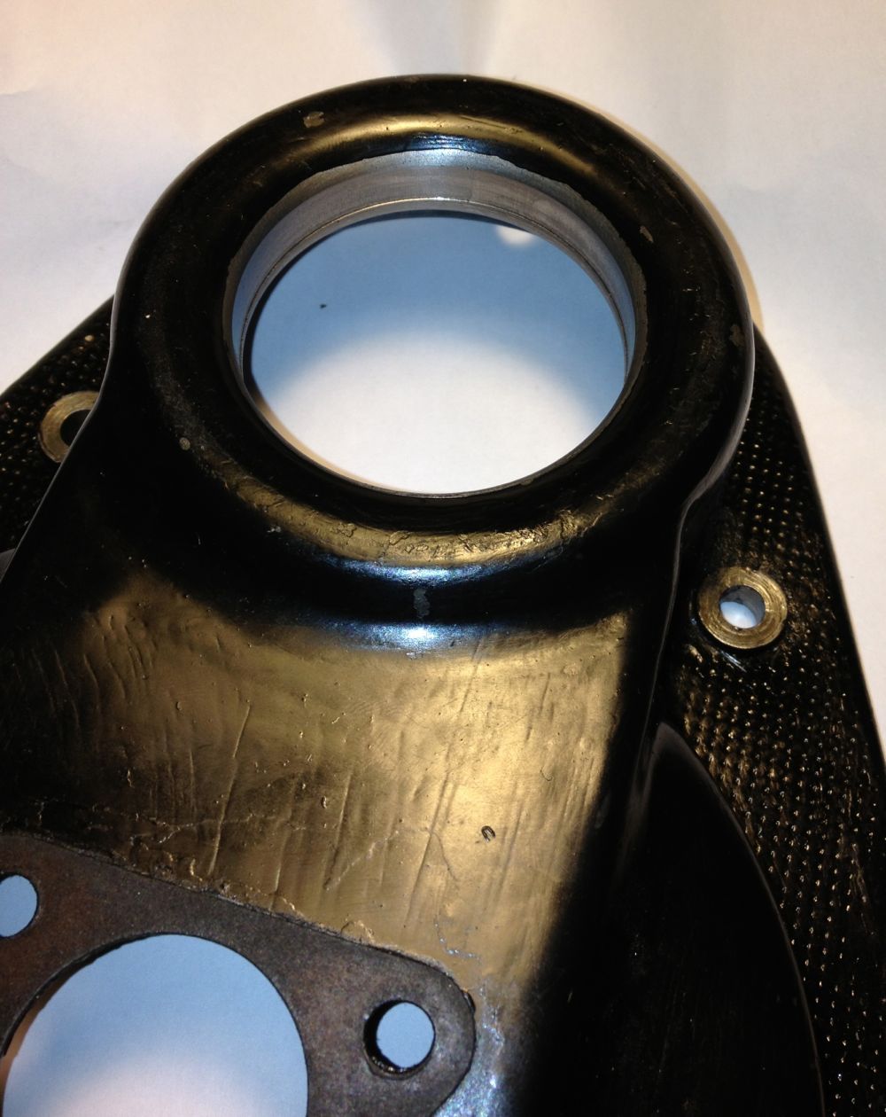
There is a slight step, which acts a s a seal stop when fitting, which you can see in the close up.
To make it easier to fit the seal square and not push it in so far I made a stepped mandrel out of some scrap ABS.
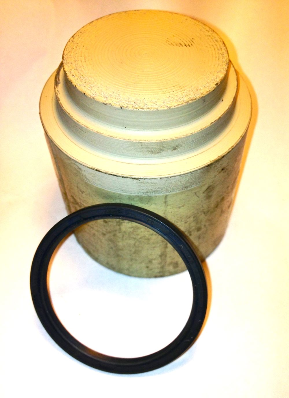
To fit the seal, place on the tool, and then push into place.
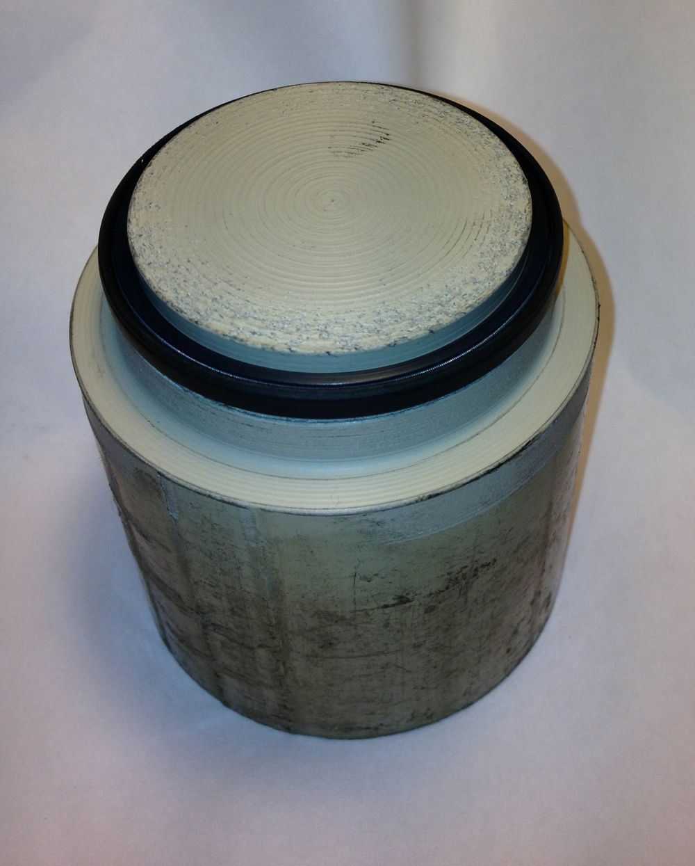
Job done.
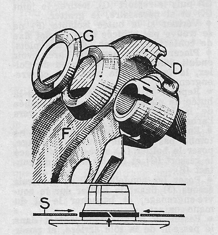
Note I will not be fitting the slingers (G & F in the diagram at the start of the blog) inside the timing cover, as the oil mist and splash lubrication to the gears will lubricate the seal, and stop it sticking or drying out.
The original solution is to use a piston ring type seal
There is a groove in the front pulley (arrowed) to accept a piston ring type seal, with a hardened surface in the cover for it to rotate in.
There are a few ways to create a seal here, the easiest at the moment is to do this. Place the front pulley in a lathe, aka damp Colchester
i
Check it’s running true, and machine to 40.02 mm, but don’t worry if you go too small as bearing retainer will save your bacon.
Install the 40 x 45 x 17 inner ring
Next up modify the timing cover, I used a local engineering company to open up the hole to Ø52mm, the idea being I could use a 42 x 52 x 4, 5, 7 or 8 mm deep R23 oil seal. These are available in Viton in the smaller widths, but Nitrile or NBR is adequate for this diameter. The 5mm is shown, but I am changing this to the 8mm version when it arrives.
There is a slight step, which acts a s a seal stop when fitting, which you can see in the close up.
To make it easier to fit the seal square and not push it in so far I made a stepped mandrel out of some scrap ABS.
To fit the seal, place on the tool, and then push into place.
Job done.
Note I will not be fitting the slingers (G & F in the diagram at the start of the blog) inside the timing cover, as the oil mist and splash lubrication to the gears will lubricate the seal, and stop it sticking or drying out.
