Speedo fix after removing ABS ECU
Tue 14 Nov 2006 Filed in: GTS1000 Electrical
A few folks out there with a Yamaha GTS1000A have removed their ABS units, and then later discovered their speedometer does not work. Not surprising when the speedo gets it's info from the ABS ECU on these bikes, but there are genuine non ABS bikes out there too. So what was doing it.
A little investigation in the wiring loom diagrams for both models suggests there is a difference at the speedometer area, so I removed the instrument cluster from a donor bike, a UK spec 4BH GTS1000A. Surprisingly, there was an undocumented sixway connector that interfaced with the speedo area, although on the ABS unit I was looking at, only four of the sixway connector pins were populated. This sixway connector fed the circuit board below, which I assumed processed the pulses to create a speedo reading.
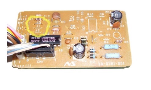
This is the board that is different, as the speedo stepper motor only has three inputs, this board has four inputs potentially, and has several outputs. One to odometer, one to the trip meter via the black horizontal connector, and a pink output to the speedo from the white vertical element.The chip is a Toshiba TD6330BP, a generic stepper motor driver, with optional external divisor inputs and outputs, as well as Schmitt circuitry, which is useful for processing inductive pickups.
After looking at the circuit board and the fiveway white strain block, I noticed the middle pin was not used and noted there was Assy(1) and Assy(2) markings plus a lot of the board is not populated with electronic components. As the speedo only has and needs three inputs, a 12V feed, a 12V ground and a pink input from the board, and this leads to the white vertical element on the left of the board, which ony uses four out of five potential solder areas. The only available space for a potential signal ground from the front wheel sensor would bridge to the board ground. Reading the specs of the chip, the ground plane is well isolated, so I thought I would feed the missing part of the inductive signal pulse into this, with the existing yellow/red wire feed being the other.
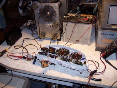
First of all, I needed to generate a pulse, fortunately I had a homemade variable speed fuel injection rig that had a single toothed wheel matched to a two wire inductive sensor, just like the Yamaha front wheel sensor...sure there wasn't a lot of teeth on it, but it would spin up to 11000 rpm, so I should get a signal. After hooking a 12V battery up to a charger...(don't you just love it when you want to do something and stupid things get in the way)...to create my power feeds, which incidentally are brown/black in large white connector block becomes +12V, black/brown in the blue connector is ground, and one feed from the inductive pickup is fixed to the yellow/red wire in the large white block , and the other makes contact with the black/brown in the blue plug.
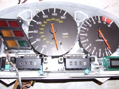
Switch on the motor and yippee it works. Switch it off and it stops!
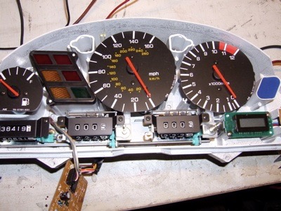
Notice how the odometer and trip meters have moved on.
So if you plan on getting rid of the ABS system on a Yamaha GTS1000A and want to get your speedo to work, you will need to jump the yellow/red wire in the ABS ECU plug to the white wire from the wheel speed sensor, and break into the loom to pick up the black/brown ground wire and splice the black wire from the front wheel sensor into it. Might be best to do this at the small white plug connector near the top of the left hand side Omega Chassis rail that connects the front wheel sensor into the main loom.
A little investigation in the wiring loom diagrams for both models suggests there is a difference at the speedometer area, so I removed the instrument cluster from a donor bike, a UK spec 4BH GTS1000A. Surprisingly, there was an undocumented sixway connector that interfaced with the speedo area, although on the ABS unit I was looking at, only four of the sixway connector pins were populated. This sixway connector fed the circuit board below, which I assumed processed the pulses to create a speedo reading.
This is the board that is different, as the speedo stepper motor only has three inputs, this board has four inputs potentially, and has several outputs. One to odometer, one to the trip meter via the black horizontal connector, and a pink output to the speedo from the white vertical element.The chip is a Toshiba TD6330BP, a generic stepper motor driver, with optional external divisor inputs and outputs, as well as Schmitt circuitry, which is useful for processing inductive pickups.
After looking at the circuit board and the fiveway white strain block, I noticed the middle pin was not used and noted there was Assy(1) and Assy(2) markings plus a lot of the board is not populated with electronic components. As the speedo only has and needs three inputs, a 12V feed, a 12V ground and a pink input from the board, and this leads to the white vertical element on the left of the board, which ony uses four out of five potential solder areas. The only available space for a potential signal ground from the front wheel sensor would bridge to the board ground. Reading the specs of the chip, the ground plane is well isolated, so I thought I would feed the missing part of the inductive signal pulse into this, with the existing yellow/red wire feed being the other.
First of all, I needed to generate a pulse, fortunately I had a homemade variable speed fuel injection rig that had a single toothed wheel matched to a two wire inductive sensor, just like the Yamaha front wheel sensor...sure there wasn't a lot of teeth on it, but it would spin up to 11000 rpm, so I should get a signal. After hooking a 12V battery up to a charger...(don't you just love it when you want to do something and stupid things get in the way)...to create my power feeds, which incidentally are brown/black in large white connector block becomes +12V, black/brown in the blue connector is ground, and one feed from the inductive pickup is fixed to the yellow/red wire in the large white block , and the other makes contact with the black/brown in the blue plug.
Switch on the motor and yippee it works. Switch it off and it stops!
Notice how the odometer and trip meters have moved on.
So if you plan on getting rid of the ABS system on a Yamaha GTS1000A and want to get your speedo to work, you will need to jump the yellow/red wire in the ABS ECU plug to the white wire from the wheel speed sensor, and break into the loom to pick up the black/brown ground wire and splice the black wire from the front wheel sensor into it. Might be best to do this at the small white plug connector near the top of the left hand side Omega Chassis rail that connects the front wheel sensor into the main loom.
blog comments powered by Disqus
