Blog Comments
Panhard Engine Musings
Sunday 10 February 2013
The Panhard engine is intrinsically well designed, but the two things that could be improved with hindsight after having ceased production for nearly 50 years, is oil filtration & oil cooling. These two factors are fundamental in making a Panhard engine last longer, and the reason why they were vulnerable to failures in their production years.
Filtration is required because roller bearings have much less tolerance to particulates & contamination than the more widely used shell bearings, and fortunately tor Panhard owners there are various alternatives out there. Mr Guny and myself have developed suction variants, and later Mr Lauffenburger developed his pressure fed system. The latter is a comprehensive upgrade, and includes a new oil pump, the option to fit oil coolers and various other sensors.
It really doesn’t matter which one is used, as long as you employ some type of filtration. Historically, Panhard did fit a positive pressure filter off the RJH banjo feeds of the cylinders, but it was a partial system, because once the RJH system got up to pressure the main oil flow was through the camshaft gallery bypassing this arrangement.
Why did Mr Guny & myself both go down the suction route? I’d like to think we both recognised the oil flow of the Panhard engine is so low (compared to modern engines), that the pressure drop across a paper filter is negligible, and not a problem for the oil pump. This can be quite hard for people to understand, especially when surrounded by modern engines and all the technobabble that they are exposed to, but the simple fact is the Panhard engine is a low flow device, really elegantly designed, and it’s only when you start to use the engine harder in modern traffic conditions that the system gets stretched, and mainly because the oil gets too hot.
Again, there is a school of thought which says you should use OEM oils in your car even 50 years later, well that is nonsense. Do you think oil technology has stood still in that time, so don’t expect your engine to suffer the old stuff either. In todays driving conditions, on a summers day going down the motorway, you will exceed the oil temperature limits of straight mineral oil frequently, however around town stuck in traffic with little airflow only occasionally.
What does this tell you? Simply, the engine cannot dissipate the heat in the oil. So how to do something about this? Heat dissipated is proportional to the flow rate, the surface area available, and also the quantity, because a small kettle boils faster than a big one. The complicated way (and not dissing anyone) is fit an oil cooler (more surface area), and a bigger oil pump and tackle the flow side of the equation, but the really smart option is to increase the oil capacity.
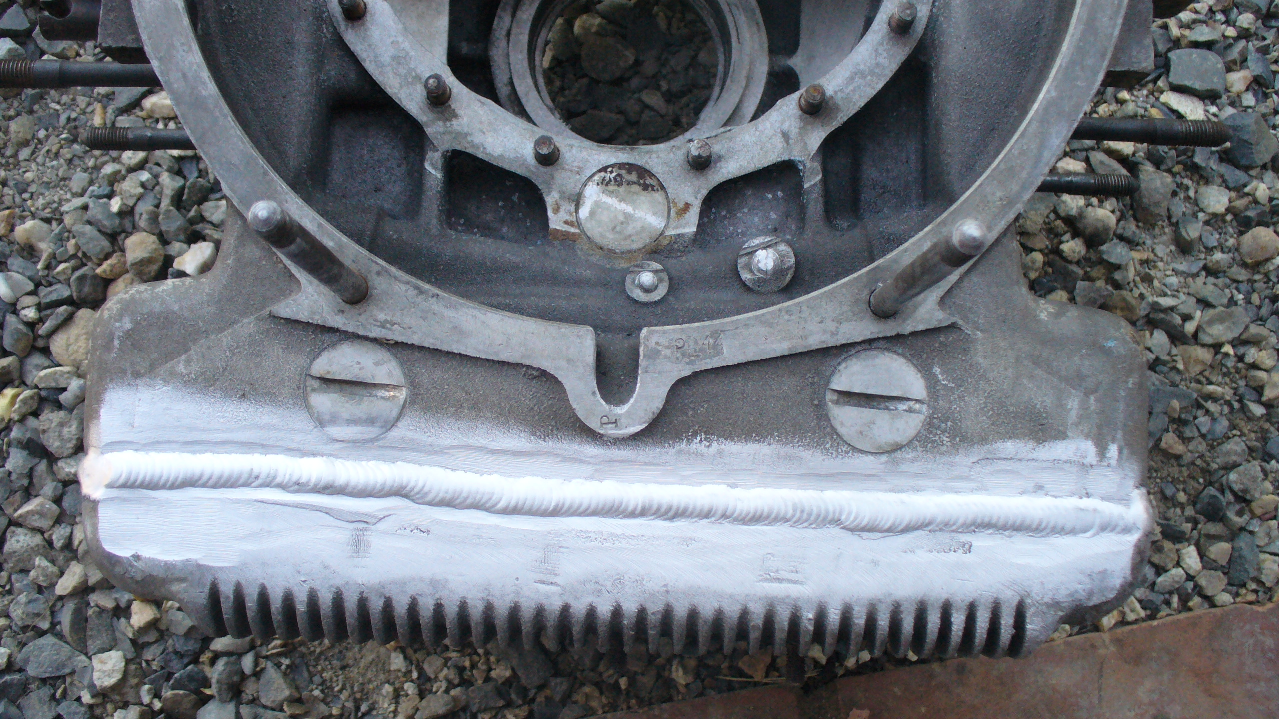
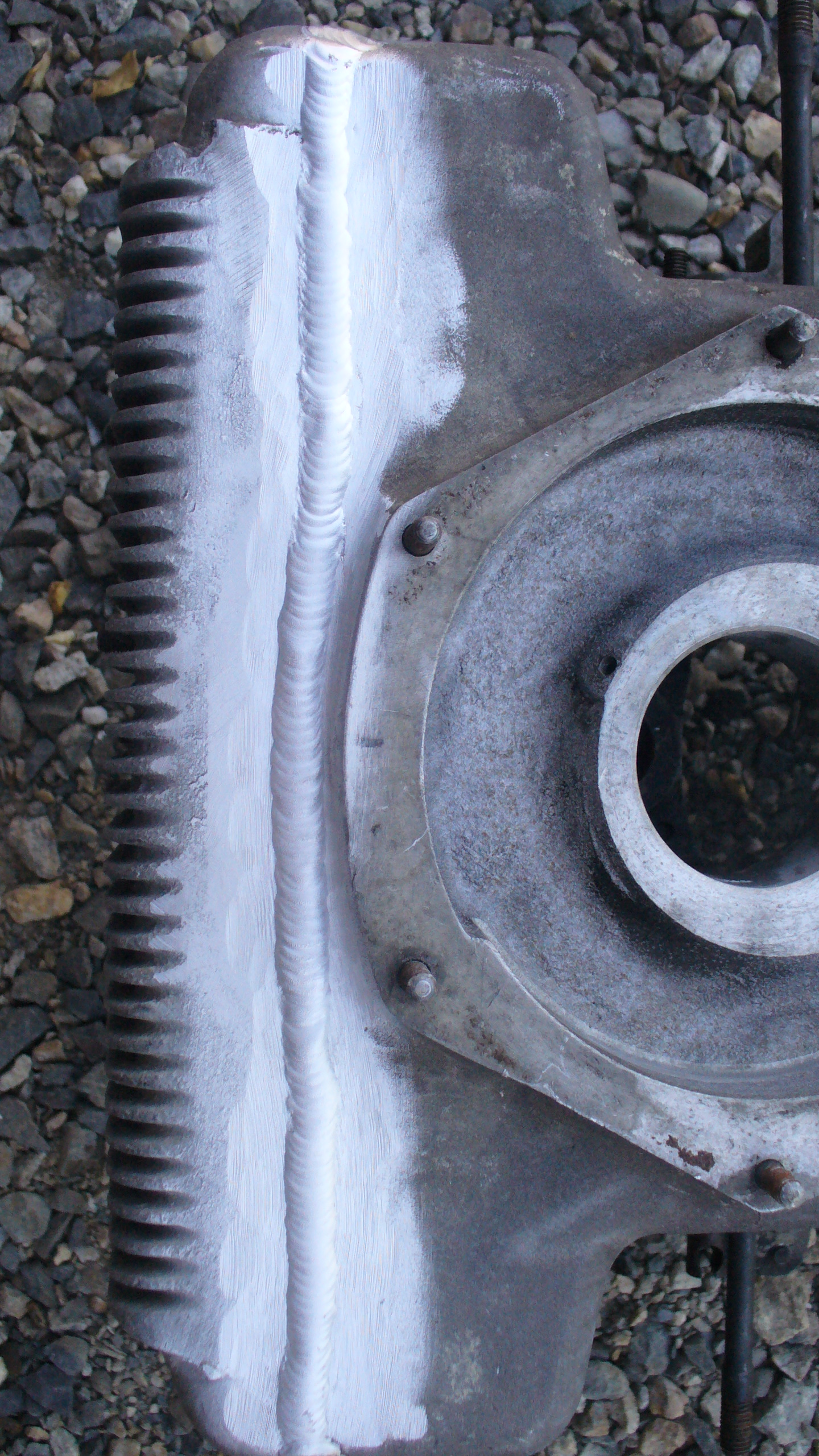
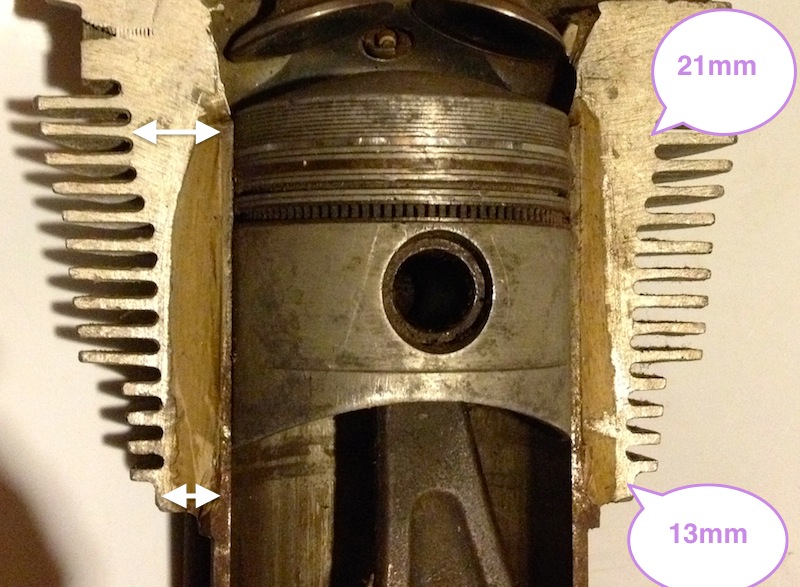
How you do this is down to the individual, one resourceful chap aka yves31 submitted these photos on the forumpanhard.free.fr. If you look closely, he has removed a thin portion off the base of his existing engine, taken another engine, and removed the sump with a higher cut line, and TIG welded the two together. All of this adds 21mm to the depth, and gives 1.3 litres of extra capacity. It is an excellent idea, but probably not easily achieved by typical owners, needs a donor crankcase, some skilful welding and requires a total stripdown of the engine. The last point is only valid if you have an engine in good condition.
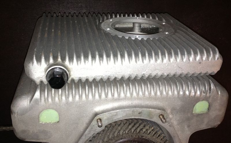
The next way, is to take a leaf out of the competition engines of the 1950’s and fit a double sump or double carter. The beauty of this system is it is easily fitted, has more surface area, yet still adds about 1.1 litres of extra oil, and can be purchased for around €140, without the oil pump adapters. This is the system that I fitted to Ron Tyrrell’s car, along with a modified oil filter kit, that placed the filter inside the crankcase, and not externally, like my other versions, which meant the extra depth of the sump (44mm) was about the same as the screw on oil filter conversion.
In tests, the oil temperature of his car dropped significantly around town, rarely went above 80ºC in drives around the rural roads. In motorway work this summer on the way to the Citröen Rally at Harrogate where 130ºC had been seen in the sump previously, the temperature never went above 115ºC, and once the ignition timing and fuelling had been dialled in, the car was travelling faster and only recording 105ºC in the sump. Another observation was, as the car was being used the oil temperature rose more slowly than before, and also recovered, whereas I seem to remember in a fateful journey to Worcester one year in the same car (without the sump addition) as the day got warmer, the temperatures kept getting hotter, until a valve seat let go.
This reinforces the best way to cool the engine is with more oil capacity, however fitting an oil cooler has other benefits in that it can be used as a heating matrix for demisting & added warmth without the oily whiffs off the air fed heating system at present.
One of the problems some Panhard owners have with filtration is the ground clearance issue, which is really is a non issue on Dyna X, PL17 & 24 models, because the exhausts hang down further either side of the sump plate, where typically an aftermarket filter is located. If adding a double sump or anything else it would be best to fit an internal filter, with the flatter sump plate, and although filter changes are not as quick, if ground clearance is an issue to the owner, an internal filter would be the best option.
Over the next few months I will be making a revised internal filter kit for the double sump variant, based on the Ron Tyrrell prototype, as Brian’s engine needs one and so does a friend in Belgium, but I am just rejigging the CAD files, as this latest double sump, has a smaller hole on the underside than previously. Ideally, I’d like to make one new sump plate fit both versions, but even though it would compromise the ground clearance by only 13mm, it’s probably better to make two different versions to negate criticism.
Filtration is required because roller bearings have much less tolerance to particulates & contamination than the more widely used shell bearings, and fortunately tor Panhard owners there are various alternatives out there. Mr Guny and myself have developed suction variants, and later Mr Lauffenburger developed his pressure fed system. The latter is a comprehensive upgrade, and includes a new oil pump, the option to fit oil coolers and various other sensors.
It really doesn’t matter which one is used, as long as you employ some type of filtration. Historically, Panhard did fit a positive pressure filter off the RJH banjo feeds of the cylinders, but it was a partial system, because once the RJH system got up to pressure the main oil flow was through the camshaft gallery bypassing this arrangement.
Why did Mr Guny & myself both go down the suction route? I’d like to think we both recognised the oil flow of the Panhard engine is so low (compared to modern engines), that the pressure drop across a paper filter is negligible, and not a problem for the oil pump. This can be quite hard for people to understand, especially when surrounded by modern engines and all the technobabble that they are exposed to, but the simple fact is the Panhard engine is a low flow device, really elegantly designed, and it’s only when you start to use the engine harder in modern traffic conditions that the system gets stretched, and mainly because the oil gets too hot.
Again, there is a school of thought which says you should use OEM oils in your car even 50 years later, well that is nonsense. Do you think oil technology has stood still in that time, so don’t expect your engine to suffer the old stuff either. In todays driving conditions, on a summers day going down the motorway, you will exceed the oil temperature limits of straight mineral oil frequently, however around town stuck in traffic with little airflow only occasionally.
What does this tell you? Simply, the engine cannot dissipate the heat in the oil. So how to do something about this? Heat dissipated is proportional to the flow rate, the surface area available, and also the quantity, because a small kettle boils faster than a big one. The complicated way (and not dissing anyone) is fit an oil cooler (more surface area), and a bigger oil pump and tackle the flow side of the equation, but the really smart option is to increase the oil capacity.
How you do this is down to the individual, one resourceful chap aka yves31 submitted these photos on the forumpanhard.free.fr. If you look closely, he has removed a thin portion off the base of his existing engine, taken another engine, and removed the sump with a higher cut line, and TIG welded the two together. All of this adds 21mm to the depth, and gives 1.3 litres of extra capacity. It is an excellent idea, but probably not easily achieved by typical owners, needs a donor crankcase, some skilful welding and requires a total stripdown of the engine. The last point is only valid if you have an engine in good condition.
The next way, is to take a leaf out of the competition engines of the 1950’s and fit a double sump or double carter. The beauty of this system is it is easily fitted, has more surface area, yet still adds about 1.1 litres of extra oil, and can be purchased for around €140, without the oil pump adapters. This is the system that I fitted to Ron Tyrrell’s car, along with a modified oil filter kit, that placed the filter inside the crankcase, and not externally, like my other versions, which meant the extra depth of the sump (44mm) was about the same as the screw on oil filter conversion.
In tests, the oil temperature of his car dropped significantly around town, rarely went above 80ºC in drives around the rural roads. In motorway work this summer on the way to the Citröen Rally at Harrogate where 130ºC had been seen in the sump previously, the temperature never went above 115ºC, and once the ignition timing and fuelling had been dialled in, the car was travelling faster and only recording 105ºC in the sump. Another observation was, as the car was being used the oil temperature rose more slowly than before, and also recovered, whereas I seem to remember in a fateful journey to Worcester one year in the same car (without the sump addition) as the day got warmer, the temperatures kept getting hotter, until a valve seat let go.
This reinforces the best way to cool the engine is with more oil capacity, however fitting an oil cooler has other benefits in that it can be used as a heating matrix for demisting & added warmth without the oily whiffs off the air fed heating system at present.
One of the problems some Panhard owners have with filtration is the ground clearance issue, which is really is a non issue on Dyna X, PL17 & 24 models, because the exhausts hang down further either side of the sump plate, where typically an aftermarket filter is located. If adding a double sump or anything else it would be best to fit an internal filter, with the flatter sump plate, and although filter changes are not as quick, if ground clearance is an issue to the owner, an internal filter would be the best option.
Over the next few months I will be making a revised internal filter kit for the double sump variant, based on the Ron Tyrrell prototype, as Brian’s engine needs one and so does a friend in Belgium, but I am just rejigging the CAD files, as this latest double sump, has a smaller hole on the underside than previously. Ideally, I’d like to make one new sump plate fit both versions, but even though it would compromise the ground clearance by only 13mm, it’s probably better to make two different versions to negate criticism.
Comments
Panhard Oil Light Piston
Saturday 02 February 2013
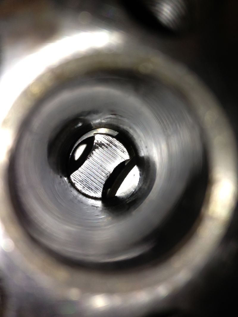
I have been asked to make an oil light piston for a friend in Belgium, and as promised here it is. This is only used when you modify the crankcase oil circuits, and although it is of similar dimensions to the OEM part, there is a built in oil pressure relief valve that only dumps oil through the side drilling to the timing gears when the camshaft gallery has a minimum of 30 psi or 2 bar pressure.
The diameter of the side drilling can be increased, but at the moment, there appears to be sufficient lubrication to the timing gears.
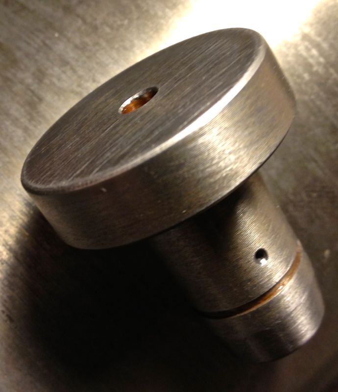
The circlip is not fitted in the following pic, and I haven’t rounded the corners at the tip. The evidence so far is it isn’t needed, but you can do this if you want.
The diameter of the side drilling can be increased, but at the moment, there appears to be sufficient lubrication to the timing gears.
The circlip is not fitted in the following pic, and I haven’t rounded the corners at the tip. The evidence so far is it isn’t needed, but you can do this if you want.
Panhard crankshaft jig
Sunday 13 January 2013
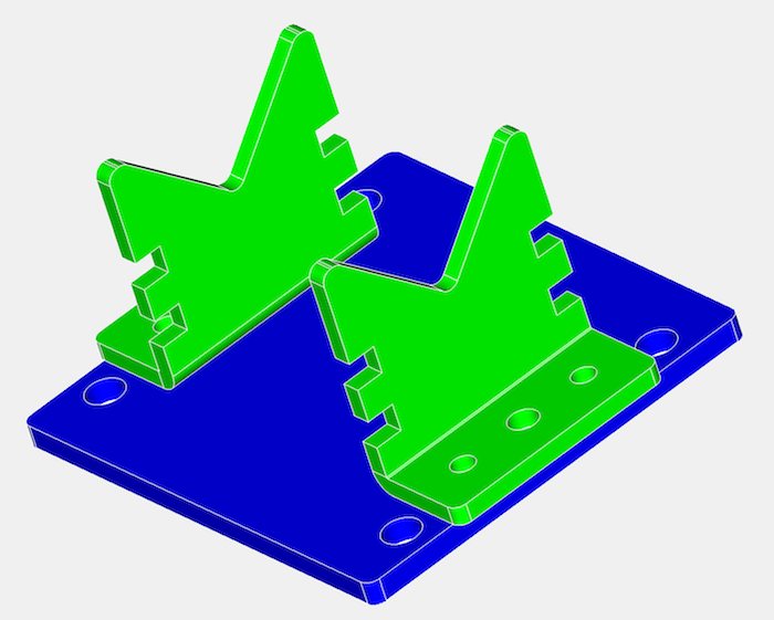
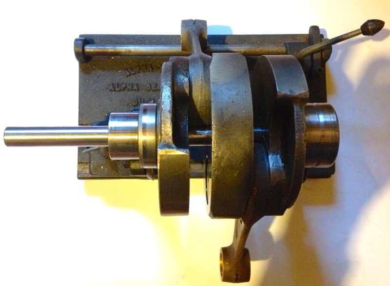
I need to make a jig to hold the crankshaft on the mill bed. I could set it up using fee blocks, but I decided if I made a dedicated jig, I could reliably and consistently machine the two holes required for pinning 180º apart. If I machine to the same depth using the digital readout, then the crankshaft should stay in balance. After looking at the problem, I decided a session at the laser cutters would be more than adequate. This is what I had in mind in CAD, without the clamping mechanism being shown.
This is the first attempt, just waiting for a few fasteners, as the shop had closed by the time I picked the parts up.

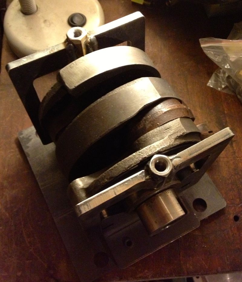
I am going to modify it further with a quick change indexing system to give a 180º setting, but first I have to put it on the mill bed, and explore the tool path fit. The Clarkson MT40 collet holder is quite large, and I now need a slightly longer carbide slot drill to get machine the required hole depth for the dowelling process. the dowels are specially made for the job, and to aid removal, I have gone for the internally threaded type to aid crankshaft rebuilding operations.
It won’t be long before I can pin the crankshafts properly.
UPDATE I am going to use a small boring bar now, I tried with a slot drill, and it “walked” and the hole was too large!
This is the first attempt, just waiting for a few fasteners, as the shop had closed by the time I picked the parts up.
I am going to modify it further with a quick change indexing system to give a 180º setting, but first I have to put it on the mill bed, and explore the tool path fit. The Clarkson MT40 collet holder is quite large, and I now need a slightly longer carbide slot drill to get machine the required hole depth for the dowelling process. the dowels are specially made for the job, and to aid removal, I have gone for the internally threaded type to aid crankshaft rebuilding operations.
It won’t be long before I can pin the crankshafts properly.
UPDATE I am going to use a small boring bar now, I tried with a slot drill, and it “walked” and the hole was too large!
Panhard external oil filter conversion - screw on filter update
Wednesday 02 January 2013
A lot of time has gone by since I did my first oil filter conversion, the first ten kits used a Champion F129 filter, whereas the later ones had a different thread and used a M20 x 1.5mm Renault Purflux filter.
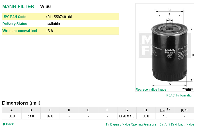
At the time the economics of making a special filter for the cars was out of the question, so it was necessary to remove the anti drain valve membrane fitted to the Purflux aka Renault Clio unit. Later on I made an internal filter version, but when I made a few external filter kits later I used a Mann Hummel W66. Details as below, but the picture is not representational, as it is only 60mm high. It is fitted with a bypass valve, which allows oil to flow should the filter clog up sufficiently to restrict the oil flow, but this is only really needed in high flow shell bearing crankshafts. In the Panhard engine, the low flow requirements and the low mileage usage they see means that the oil and filter would be changed before the bypass valve could operate, and besides the oil light would illuminate more frequently if this was happening.
One of the areas that was an improvement on the very first filter kit design was the dished area of the sump plate that received the filter cartridge was increased, so that meant there was more scope for larger diameter screw on filters.
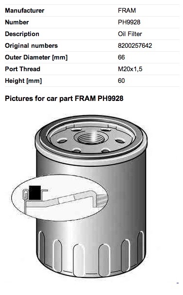
A UK PL17 owner, Gary Ockenden, who is involved in the motor trade recommended a Fram 9928, which is shown below (the picture is not representational), and this is an alternative for the Purflux LS924 & Mann Hummel W66.
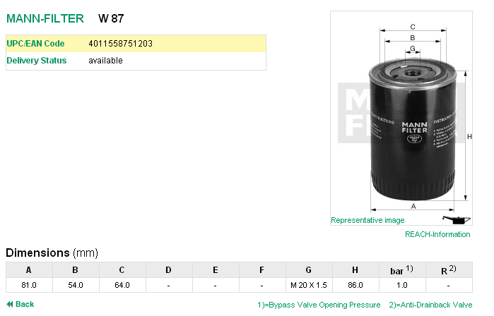
Another filter that can be used is a Mann Hummel W87, but this is some 26mm taller than the W66.
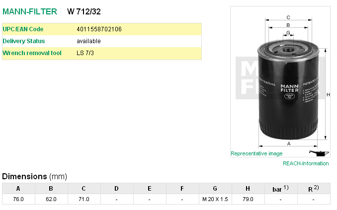
However the best filter, which has no bypass valve or anti drain valve fitted, so it is ideal on the suction side, is the Mann Hummel W712/32, but this is slightly taller by 19mm over the W66, and so better suited to the PL17 models. This model has a larger diameter as well, and so holds more oil.
The Mann 712/32 filter is also cross referenced to these numbers.
Ford 5022 739
Opel 650386
Vauxhall VOF114
GM 93156652 or 93156659
At the time the economics of making a special filter for the cars was out of the question, so it was necessary to remove the anti drain valve membrane fitted to the Purflux aka Renault Clio unit. Later on I made an internal filter version, but when I made a few external filter kits later I used a Mann Hummel W66. Details as below, but the picture is not representational, as it is only 60mm high. It is fitted with a bypass valve, which allows oil to flow should the filter clog up sufficiently to restrict the oil flow, but this is only really needed in high flow shell bearing crankshafts. In the Panhard engine, the low flow requirements and the low mileage usage they see means that the oil and filter would be changed before the bypass valve could operate, and besides the oil light would illuminate more frequently if this was happening.
One of the areas that was an improvement on the very first filter kit design was the dished area of the sump plate that received the filter cartridge was increased, so that meant there was more scope for larger diameter screw on filters.
A UK PL17 owner, Gary Ockenden, who is involved in the motor trade recommended a Fram 9928, which is shown below (the picture is not representational), and this is an alternative for the Purflux LS924 & Mann Hummel W66.
Another filter that can be used is a Mann Hummel W87, but this is some 26mm taller than the W66.
However the best filter, which has no bypass valve or anti drain valve fitted, so it is ideal on the suction side, is the Mann Hummel W712/32, but this is slightly taller by 19mm over the W66, and so better suited to the PL17 models. This model has a larger diameter as well, and so holds more oil.
The Mann 712/32 filter is also cross referenced to these numbers.
Ford 5022 739
Opel 650386
Vauxhall VOF114
GM 93156652 or 93156659
Panhard camshaft timing gears
Tuesday 01 January 2013
I was having a conversation with a fellow Panhard enthusiast, and he was querying the modifications to the timing gear oil level I make. At the end of the conversation, it was mentioned whether I had seen the modified DB timing gears, to which I said no. Later that day, I received some pictures via email.
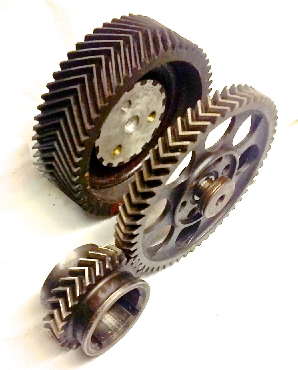
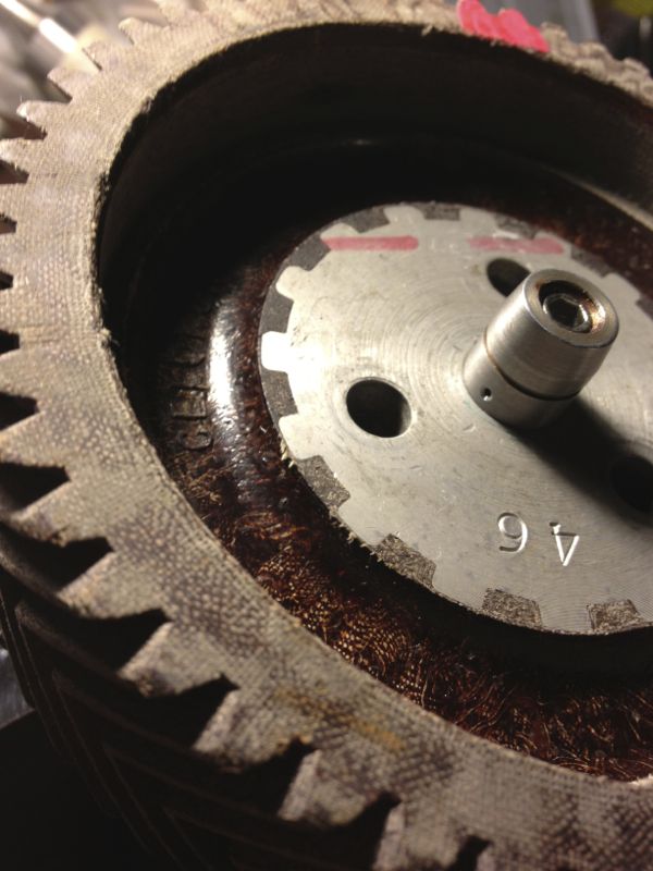
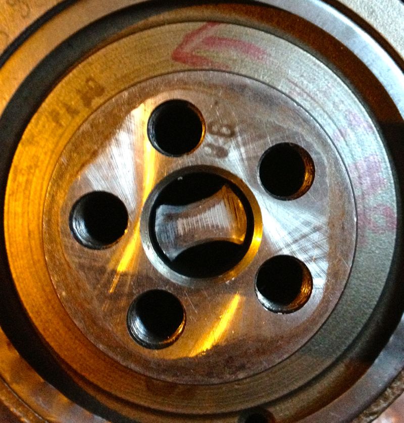
What’s really interesting, is I could never understand why the aluminium timing gear that replaces the fibre one was made the same width, as aluminium is so much stronger than the fibre aka Celeron gear. Looking at this DB gear, which is made in steel the racing guys took that to its logical conclusion, and reduced the width. This reduces the pumping losses too, as well as the inertial ones, so it seems there is scope for improvements here too.
Notice the extra mounting holes in the new gear, six versus three, which might have been some further camshaft timing adjustment mechanism.
Thank you Stefaan for the picture.
Panhard crankshaft truing
Sunday 04 November 2012
Too cold to work in the roof of the house first thing in the morning today, so for a few hours while it got warmer, I decided to make my crankshaft truing tool on the Elliot mill. I can’t do anything else until I collect the other liners and crankshafts, so it seemed fair to make a start on something else.
Several months ago, Martin McClarence had given me an ex Woody crankshaft to true up that had turned somehow.
When he installed this low mileage crankshaft (10 miles) into his engine, it decided to let go a little and break the piston ring seal and damage the timing gear cover. I knew it was bent because Martin couldn’t fit the rear bearing plate in the crankcase, when the crankshaft was installed in the front bearing, and this was confirmed by the wobble I saw on the Alpha crank truing rig. It is very awkward to true one of these cranks on a traditional crankshaft rig, which is why making the special tool is so beneficial.
After making my crankshaft tool, I decided to test it out on Martin’s crankshaft, and pleasingly it went down the middle until it hit the rear crankshaft web. A quick close up snap will show the tool and crankshaft hole are not concentric.
However, after looking at the crankshaft, a good swipe with a brand new #4 Thor from a decent height might suffice to put things right. It had to be bigger than my old crank bashing hammer, as these crankshafts have quite large pins, compared to the motorcycle crankshafts I have messed with in the past..Thor in right hand, crank in left, a couple of big swings and a few big hits later, and this is the result.
A quick check on the Alpha crankshaft truing rig, and it gets the all clear.
Now the question is do I leave it be, do i pin it or do I weld it with a pencil torch and TID set? I’ll let Martin make the decision.
UPDATE
He has and he’d like it pinning, so the saga continues...
Panhard bare cylinder isn't tapered (updated)
Friday 02 November 2012
I have long said that boring a tapered liner is extremely difficult, and I often wondered how Panhard did it, but today I found out for sure.
I have measured the internal diameters of a bare aluminium cylinder casting, and it is truly parallel internally. I have also measured a new old stock liner and this was parallel internally and externally, so it was suggested by me, that Panhard machined a tapered liner was the stuff of legends or folklore.
I actually surprised myself by accidentally stumbling upon a method of boring a tapered liner the other day, and although I might still do this using the boring bar directly, I didn’t think this is what Panhard did, as it’s not really a production method. So how else could this be achieved?
It was possible that Panhard used a tapered honing process, but again it’s way too slow and therefore probably not what Panhard did either.
I knew the cylinder finning and casting were tapered, and I wondered whether this fact was lost in translation when the cylinder was being described in the press releases, but then I had my eureka moment and I discovered an even easier way. I was drawing up a new cylinder in CAD looking at the original casting, and taking measurements, when it hit me.
The answer lies in the liner or sleeve is an interference fit in the cylinder casting, and depending on the interference, the strength of the cylinder casting (thickness of the walls) this determines how much the liner distorts, this distortion is what tapers the cylinder bore.
When the bare cylinder is warmed up the interference fit is lost, and the cold liner or sleeve is “dropped” in place, but when it cools the cylinder starts to squeeze the liner. However the cylinder walls have different thicknesses tapering from the bottom of the liner to the top, as in the picture below.
What this means is for a given interference fit along its length, the liner will be squeezed more at the top than the bottom, because the cylinder is much stiffer in compression at the top, and less stiff as the liner moves away from the top. The reality is on a cold bore today when it was 4ºC, the diameters measured across the liner from top to bottom are as shown.
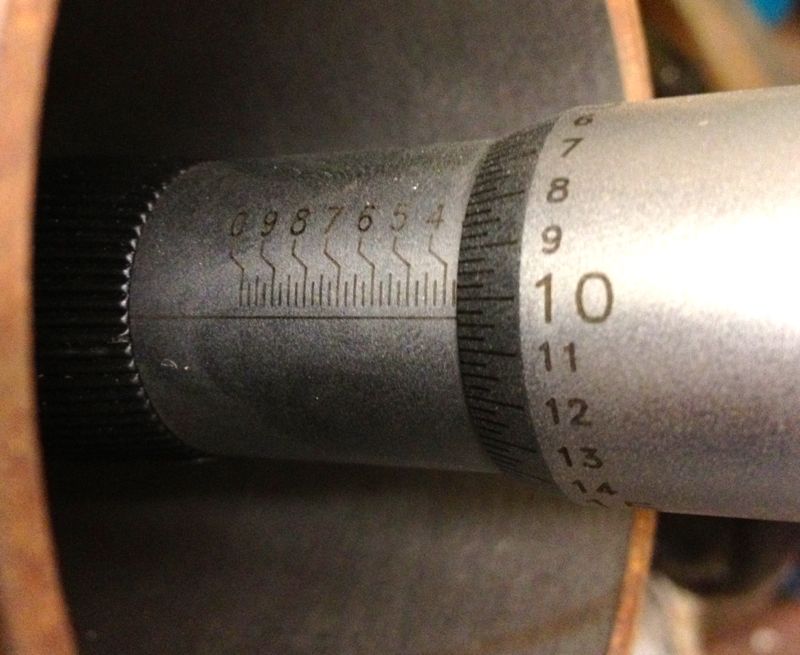
3.3604” at the very top (closest to the combustion chamber in the above photo)
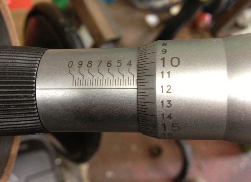
3.3620” in the middle of the liner, measured roughly in the middle of the cylinder casting.
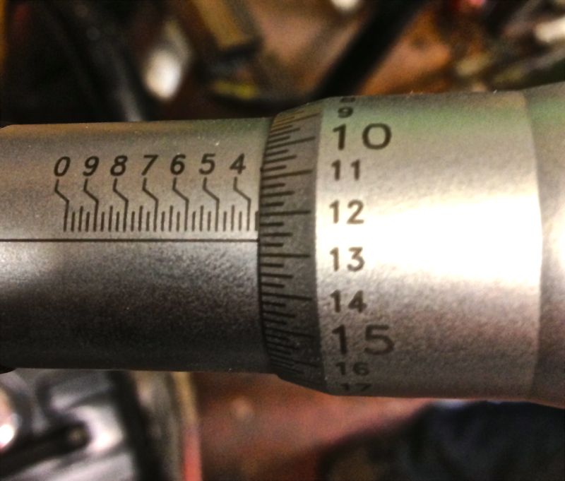
3.3626” in the liner, measured at the base of the cylinder casting.

Lastly, at the base of the liner skirt, which is the bit that isn’t contained by the cylinder casting, that is where the spigot goes into the crankcase, the actual machined bore diameter of 3.3670” is seen again on the micrometer.
There is a 0.007” variation on a cold cylinder from top to bottom, and no wonder people often said some engines were quiet and slow running, until they warmed up slightly!
The mystery as to how the cylinder bore becomes tapered is finally solved for me at least, and possibly a few others too.
It also means you can parallel bore the cylinder casting or sleeve, and you will not destroy the factory taper, but you must always take the liner or sleeve out of the cylinder casting otherwise you will.
If you make a larger bore engine using the standard cylinder casting & original interference fit, you will reduce the taper effect at the top, because you have reduced the wall thickness and compressive stiffness pro rata.
I am almost ready to machine the cylinders to suit the new pistons, but I need to explore a couple of other things first, namely how perpendicular is the bore, and how does the cylinder bore change with temperature versus the piston crown & ring body, which will establish the actual bore size required for the liner or sleeve.
UPDATE Saturday 3 November 2012
It seems that at about a cylinder temperature of 120ºC the bore is truly parallel, and approximately 0.007” larger at the combustion chamber end of the liner, than when it is cold.
I have measured the internal diameters of a bare aluminium cylinder casting, and it is truly parallel internally. I have also measured a new old stock liner and this was parallel internally and externally, so it was suggested by me, that Panhard machined a tapered liner was the stuff of legends or folklore.
I actually surprised myself by accidentally stumbling upon a method of boring a tapered liner the other day, and although I might still do this using the boring bar directly, I didn’t think this is what Panhard did, as it’s not really a production method. So how else could this be achieved?
It was possible that Panhard used a tapered honing process, but again it’s way too slow and therefore probably not what Panhard did either.
I knew the cylinder finning and casting were tapered, and I wondered whether this fact was lost in translation when the cylinder was being described in the press releases, but then I had my eureka moment and I discovered an even easier way. I was drawing up a new cylinder in CAD looking at the original casting, and taking measurements, when it hit me.
The answer lies in the liner or sleeve is an interference fit in the cylinder casting, and depending on the interference, the strength of the cylinder casting (thickness of the walls) this determines how much the liner distorts, this distortion is what tapers the cylinder bore.
When the bare cylinder is warmed up the interference fit is lost, and the cold liner or sleeve is “dropped” in place, but when it cools the cylinder starts to squeeze the liner. However the cylinder walls have different thicknesses tapering from the bottom of the liner to the top, as in the picture below.
What this means is for a given interference fit along its length, the liner will be squeezed more at the top than the bottom, because the cylinder is much stiffer in compression at the top, and less stiff as the liner moves away from the top. The reality is on a cold bore today when it was 4ºC, the diameters measured across the liner from top to bottom are as shown.
3.3604” at the very top (closest to the combustion chamber in the above photo)
3.3620” in the middle of the liner, measured roughly in the middle of the cylinder casting.
3.3626” in the liner, measured at the base of the cylinder casting.
Lastly, at the base of the liner skirt, which is the bit that isn’t contained by the cylinder casting, that is where the spigot goes into the crankcase, the actual machined bore diameter of 3.3670” is seen again on the micrometer.
There is a 0.007” variation on a cold cylinder from top to bottom, and no wonder people often said some engines were quiet and slow running, until they warmed up slightly!
The mystery as to how the cylinder bore becomes tapered is finally solved for me at least, and possibly a few others too.
It also means you can parallel bore the cylinder casting or sleeve, and you will not destroy the factory taper, but you must always take the liner or sleeve out of the cylinder casting otherwise you will.
If you make a larger bore engine using the standard cylinder casting & original interference fit, you will reduce the taper effect at the top, because you have reduced the wall thickness and compressive stiffness pro rata.
I am almost ready to machine the cylinders to suit the new pistons, but I need to explore a couple of other things first, namely how perpendicular is the bore, and how does the cylinder bore change with temperature versus the piston crown & ring body, which will establish the actual bore size required for the liner or sleeve.
UPDATE Saturday 3 November 2012
It seems that at about a cylinder temperature of 120ºC the bore is truly parallel, and approximately 0.007” larger at the combustion chamber end of the liner, than when it is cold.
Panhard bare cylinder isn't tapered
Saturday 15 September 2012
Panhard liners have had tapered bores since the early days. However when it’s time to rebuild them, I never found this out.
It was assumed by others, and I had no reason to question whether the liner was tapered internally, or perhaps the aluminium cylinder itself? The reasoning behind this was, if the aluminium cylinder was slightly narrower at the combustion chamber end, it would squeeze the sleeve and so make it tapered.
Yesterday, I got a Tesa three point bore micrometer in the post, and I was finally able to measure the internal bore of the aluminium cylinder.
I measured the bottom, middle and top of the bore of the bare aluminium cylinder, that’s without a liner or sleeve being fitted.
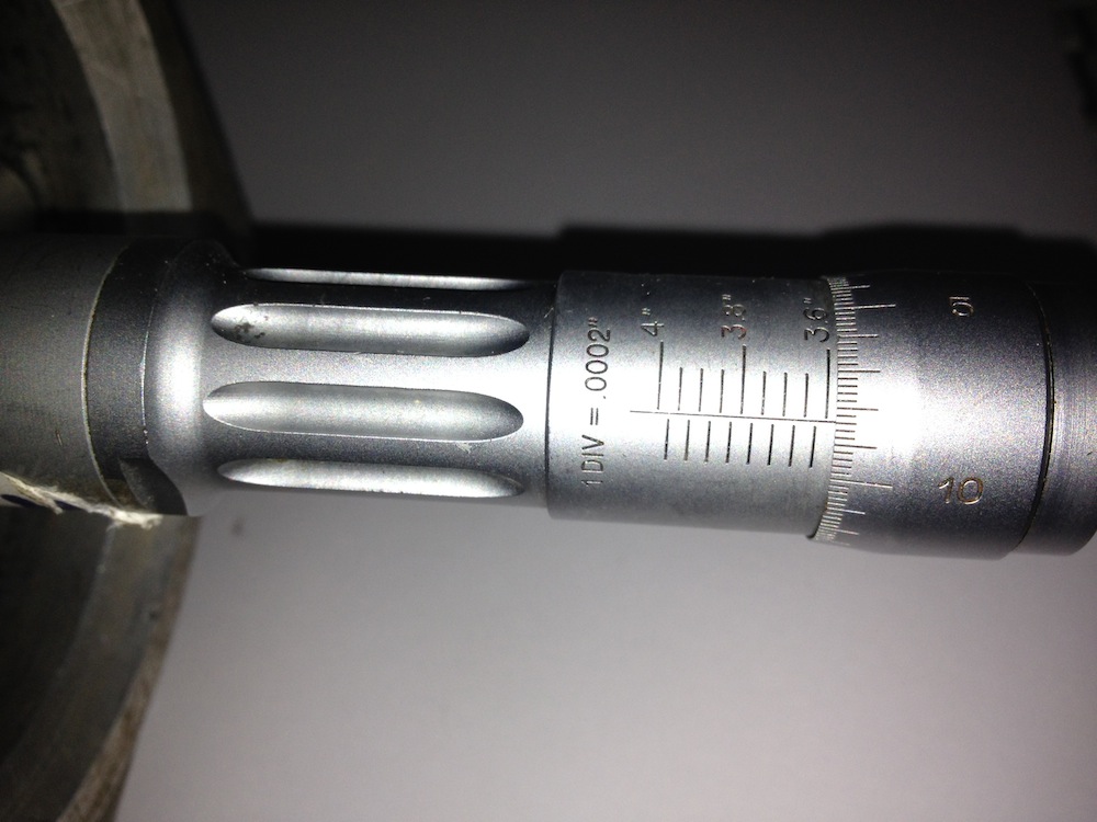
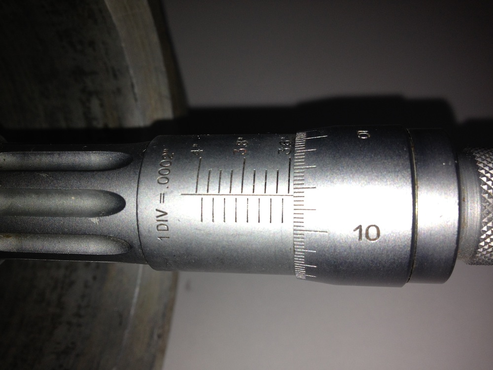
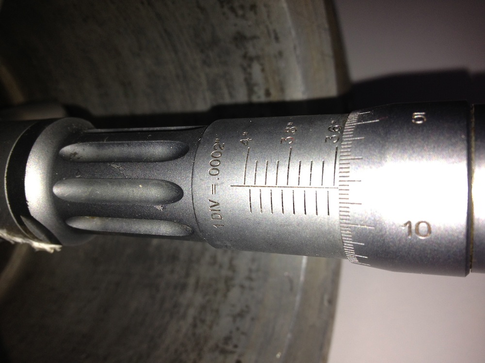
The divisions of the micrometer are 0.0002” or 2/10ths of a thou. There is no taper on the bare cylinder, so thats’s another bit of folklore or legend out of the way, and the only other way to achieve this would be to make the internal sleeve or cast iron liner taper outwards at the top, so that when it is inserted in the heated cylinder, upon cooling it compresses slightly more at the top than the bottom. Next up is to measure a few sleeves or liners and check whether this was done.
Interestingly the days of tapered bores were numbered with improvements in aluminium piston alloys and better machining, and Panhards have bigger issues with their piston design, so obsessing about having a tapered bore is rather irrelevant and futile.
UPDATE 23 September 2012
I measured the matching sleeve, taken from the aluminium cylinder above, and the external diameters are truly parallel, so I now know I will not have any issues when I bore the cylinder liner or sleeve.
It was assumed by others, and I had no reason to question whether the liner was tapered internally, or perhaps the aluminium cylinder itself? The reasoning behind this was, if the aluminium cylinder was slightly narrower at the combustion chamber end, it would squeeze the sleeve and so make it tapered.
Yesterday, I got a Tesa three point bore micrometer in the post, and I was finally able to measure the internal bore of the aluminium cylinder.
I measured the bottom, middle and top of the bore of the bare aluminium cylinder, that’s without a liner or sleeve being fitted.
The divisions of the micrometer are 0.0002” or 2/10ths of a thou. There is no taper on the bare cylinder, so thats’s another bit of folklore or legend out of the way, and the only other way to achieve this would be to make the internal sleeve or cast iron liner taper outwards at the top, so that when it is inserted in the heated cylinder, upon cooling it compresses slightly more at the top than the bottom. Next up is to measure a few sleeves or liners and check whether this was done.
Interestingly the days of tapered bores were numbered with improvements in aluminium piston alloys and better machining, and Panhards have bigger issues with their piston design, so obsessing about having a tapered bore is rather irrelevant and futile.
UPDATE 23 September 2012
I measured the matching sleeve, taken from the aluminium cylinder above, and the external diameters are truly parallel, so I now know I will not have any issues when I bore the cylinder liner or sleeve.
Panhard musings
Monday 07 May 2012
I collected another Panhard crankshaft the other day to true up and lock in place, as it’s definitely not running concentric. It looks like the crank has turned ever so slightly on the crank pins and has a rather eccentric wobble.
As I am doing another crankshaft repair for Brian, I thought I’d compare the two, and at least this new crank confirms the other is too long between the bearings. In the discussions I had with the owner, I was bemused that somebody can spend a lot of money on bodywork and then baulk at the price of an engine.
Any engine that is going to get reconditioned will cost far more than swapping out for another. Its inevitable that the economics of doing so are questionable, but when you are faced with an older engine that is flawed, you’d think that would push the argument towards reconditioning, instead of just making do with any lump to hand.
In the case of the Panhard flat twin, unless you mod the lubrication circuits and increase the oil capacity you will be forever into a rebuild cycle, as these engines have some basic design faults. Panhard never had the money to eradicate these deficiencies, and whereas the engine initially was well designed, its’ subsequent development (to combat service faults) by different Panhard employees was not up to scratch as they missed the basics.
Unfortunately, very few people can see this point of view, and they seem to think you have to look to Panhards’ homeland for the best solutions, but there are no boundaries to good engineering or design. The UK has been a hub of motorsport development ever since Panhard started on their slippery slope to closure, and during this period British companies have seen dominance in World Rally cars and Formula 1. All this activity spins down to the lowest forms of motorsport, such as karting and clubman racing, and is also reflected in specialist educational courses available at the universities.
Nobody is suggesting that Panhards need F1 technology, but the companies that make parts for this industry have a huge expertise in material technology and manufacturing that can be applied to our engines, but only if you are open minded.
I hope over the next few months to surprise at least one person with the things I am working on, drop me a line if you are interested too.
Panhard rebirth
Thursday 23 June 2011
Panhard work is being restarted and now I’m going to get serious. It’s been a long time coming, but thanks to my other interests, I have some new tricks up my sleeve…traditionalists beware. Read More...
Panhard retrospective
Monday 12 November 2007
Going to add a few pages about Panhards in the next few days. I used to play with these some years ago, and would love to do more with them, but they have to stay on the back burner for longer yet. Greetings to fellow Panhard enthusiasts the world over. My speciality was tuning and redesigning the oil lubrication circuits, including an oil filter conversion. I also converted a Citroen 2CV electronic ignition and adapted it to fit a Panhard.
I will update this page with a catalogue of retrospective images when I find them, and a take a few pics of the development parts I made.
I will update this page with a catalogue of retrospective images when I find them, and a take a few pics of the development parts I made.
