Panhard Oil
Panhard Oil Lubrication Musings
Friday 15 March 2013
I am writing this piece to try and get past some misconceptions some people seem to have about Panhard engines and their oil circuits. I will edit this over the next few weeks, and try and make this easier to grasp, and I hope to translate a little of this for my French friends who visit my website.
Panhard engines evolved over time, as they needed more horsepower and had to respond to service failures. The single biggest lubrication change came to the front cylinder crankshaft oil circuit, which was modified and adapted to cure a premature wear problem to this cylinders big end bearings.
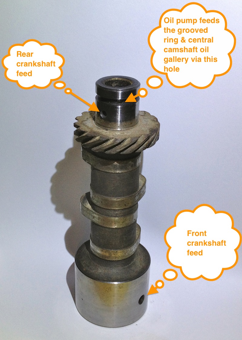
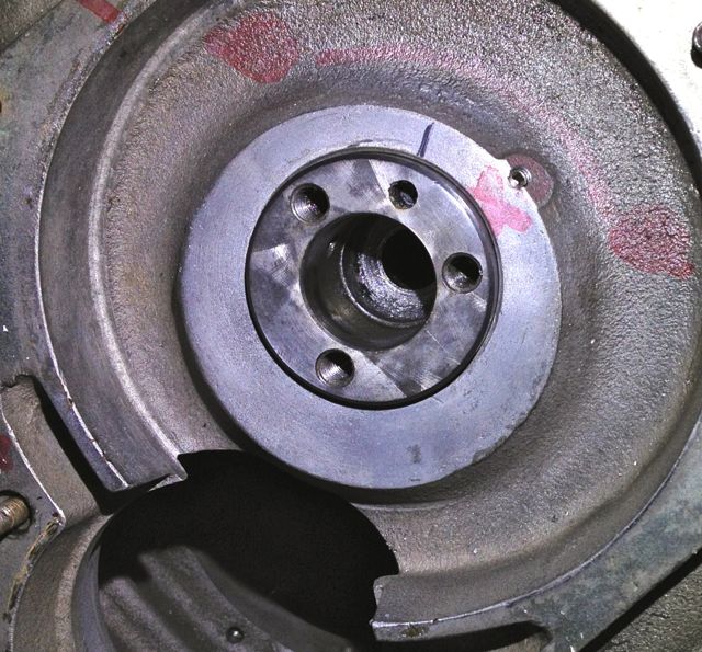
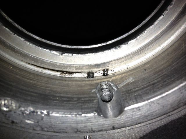
Originally the oil system was well designed, but a misplaced hole marginalised the oil supply at the front of the crankshaft compared to the rear. The oil supply to the timing gears was the problem, as can be seen in the picture below, labelled timing gear oil feed. This hole lowered the oil pressure to the slinger oil feed via the camshaft, so as the pump output dropped, the oil supply became deficient enough to accelerate the wear and cause service failures.
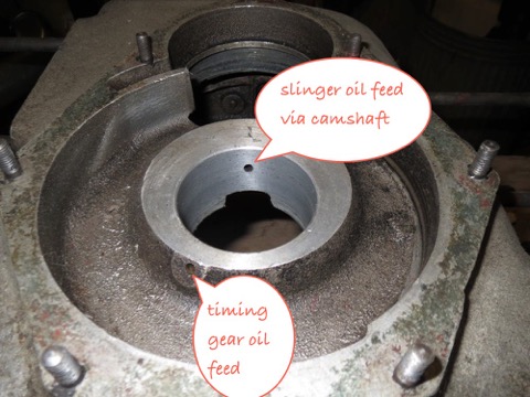
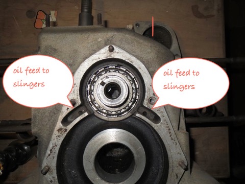
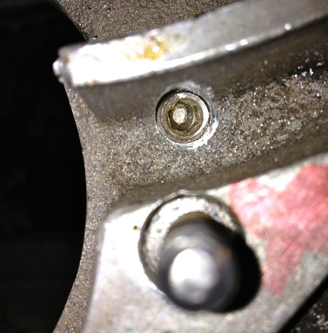
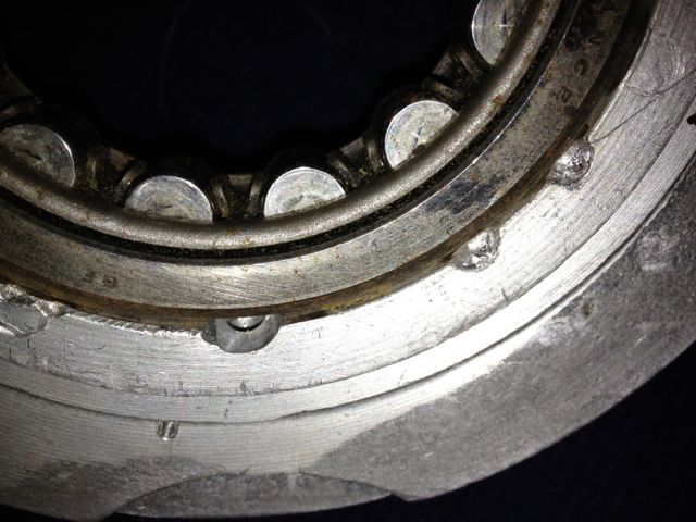
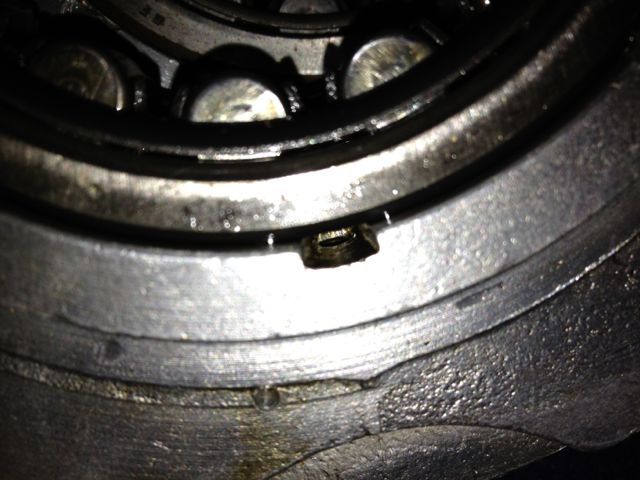
The later engines, had a modified oil delivery system, where the slinger oil feed was removed, and all the oil went into the timing gear case, and relied on the churning of the gears to splash lubricate and purge the oil into the slingers via two new high level holes. These are shown in the picture below, and labelled oil feed to slingers. The original drain holes that returned oil to the sump were filled in or not made.
All that is needed to restore the oil to how it should have been designed, is to plug the timing gear oil feed and replace this with a central or common feed from the camshaft oil gallery. This is easily achieved by modifying or replacing the oil light piston with a bespoke design.
I had done this previously to various engines over the last few years, but refined it to include a bypass valve inside the oil light, so maintain a good pressure in the camshaft oil gallery. The small hole sprays an oil mist into the timing gear cavity, and lubricates the camshaft and crankshaft gear.
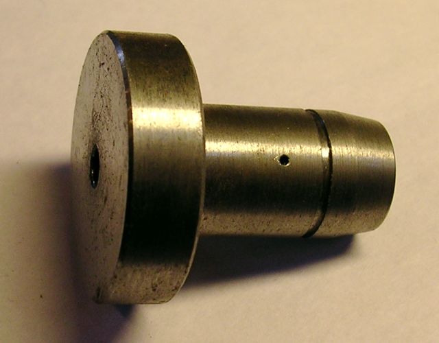
I also fitted a new nose to this, made of brass, but it wasn’t necessary, because there was no adverse wear to the other component.
UPDATE 15 September 2013
Lately, I have modified the design further by enlarging the hole, and using it as the oil pump pressure relief valve, that way the pumped oil isn’t wasted it used to lubricate the timing gears. The only thing I should point out, is that I create a lower oil return, so I don’t saturate the timing gears in oil and incur churning losses. Typical splash lubrication system, don’t immerse more than a third of the gear diameter.
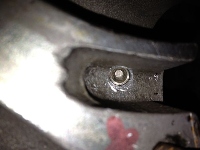
I made the holes here on the 2012 engine, but I now make them slightly lower. As this was a M10 engine, I had to plug the slinger oil feeds with an M8 set screw & a dab of Loctite, and I also restored the original camshaft oil feed that passed through the crankcase, and made a new exit under the bearing. I also enlarged the hole slight at the camshaft interface to equalise the port timings front and rear, which is something Panhard never did.
Panhard engines evolved over time, as they needed more horsepower and had to respond to service failures. The single biggest lubrication change came to the front cylinder crankshaft oil circuit, which was modified and adapted to cure a premature wear problem to this cylinders big end bearings.
Originally the oil system was well designed, but a misplaced hole marginalised the oil supply at the front of the crankshaft compared to the rear. The oil supply to the timing gears was the problem, as can be seen in the picture below, labelled timing gear oil feed. This hole lowered the oil pressure to the slinger oil feed via the camshaft, so as the pump output dropped, the oil supply became deficient enough to accelerate the wear and cause service failures.
The later engines, had a modified oil delivery system, where the slinger oil feed was removed, and all the oil went into the timing gear case, and relied on the churning of the gears to splash lubricate and purge the oil into the slingers via two new high level holes. These are shown in the picture below, and labelled oil feed to slingers. The original drain holes that returned oil to the sump were filled in or not made.
All that is needed to restore the oil to how it should have been designed, is to plug the timing gear oil feed and replace this with a central or common feed from the camshaft oil gallery. This is easily achieved by modifying or replacing the oil light piston with a bespoke design.
I had done this previously to various engines over the last few years, but refined it to include a bypass valve inside the oil light, so maintain a good pressure in the camshaft oil gallery. The small hole sprays an oil mist into the timing gear cavity, and lubricates the camshaft and crankshaft gear.
I also fitted a new nose to this, made of brass, but it wasn’t necessary, because there was no adverse wear to the other component.
UPDATE 15 September 2013
Lately, I have modified the design further by enlarging the hole, and using it as the oil pump pressure relief valve, that way the pumped oil isn’t wasted it used to lubricate the timing gears. The only thing I should point out, is that I create a lower oil return, so I don’t saturate the timing gears in oil and incur churning losses. Typical splash lubrication system, don’t immerse more than a third of the gear diameter.
I made the holes here on the 2012 engine, but I now make them slightly lower. As this was a M10 engine, I had to plug the slinger oil feeds with an M8 set screw & a dab of Loctite, and I also restored the original camshaft oil feed that passed through the crankcase, and made a new exit under the bearing. I also enlarged the hole slight at the camshaft interface to equalise the port timings front and rear, which is something Panhard never did.
Comments
Panhard Engine Musings
Sunday 10 February 2013
The Panhard engine is intrinsically well designed, but the two things that could be improved with hindsight after having ceased production for nearly 50 years, is oil filtration & oil cooling. These two factors are fundamental in making a Panhard engine last longer, and the reason why they were vulnerable to failures in their production years.
Filtration is required because roller bearings have much less tolerance to particulates & contamination than the more widely used shell bearings, and fortunately tor Panhard owners there are various alternatives out there. Mr Guny and myself have developed suction variants, and later Mr Lauffenburger developed his pressure fed system. The latter is a comprehensive upgrade, and includes a new oil pump, the option to fit oil coolers and various other sensors.
It really doesn’t matter which one is used, as long as you employ some type of filtration. Historically, Panhard did fit a positive pressure filter off the RJH banjo feeds of the cylinders, but it was a partial system, because once the RJH system got up to pressure the main oil flow was through the camshaft gallery bypassing this arrangement.
Why did Mr Guny & myself both go down the suction route? I’d like to think we both recognised the oil flow of the Panhard engine is so low (compared to modern engines), that the pressure drop across a paper filter is negligible, and not a problem for the oil pump. This can be quite hard for people to understand, especially when surrounded by modern engines and all the technobabble that they are exposed to, but the simple fact is the Panhard engine is a low flow device, really elegantly designed, and it’s only when you start to use the engine harder in modern traffic conditions that the system gets stretched, and mainly because the oil gets too hot.
Again, there is a school of thought which says you should use OEM oils in your car even 50 years later, well that is nonsense. Do you think oil technology has stood still in that time, so don’t expect your engine to suffer the old stuff either. In todays driving conditions, on a summers day going down the motorway, you will exceed the oil temperature limits of straight mineral oil frequently, however around town stuck in traffic with little airflow only occasionally.
What does this tell you? Simply, the engine cannot dissipate the heat in the oil. So how to do something about this? Heat dissipated is proportional to the flow rate, the surface area available, and also the quantity, because a small kettle boils faster than a big one. The complicated way (and not dissing anyone) is fit an oil cooler (more surface area), and a bigger oil pump and tackle the flow side of the equation, but the really smart option is to increase the oil capacity.
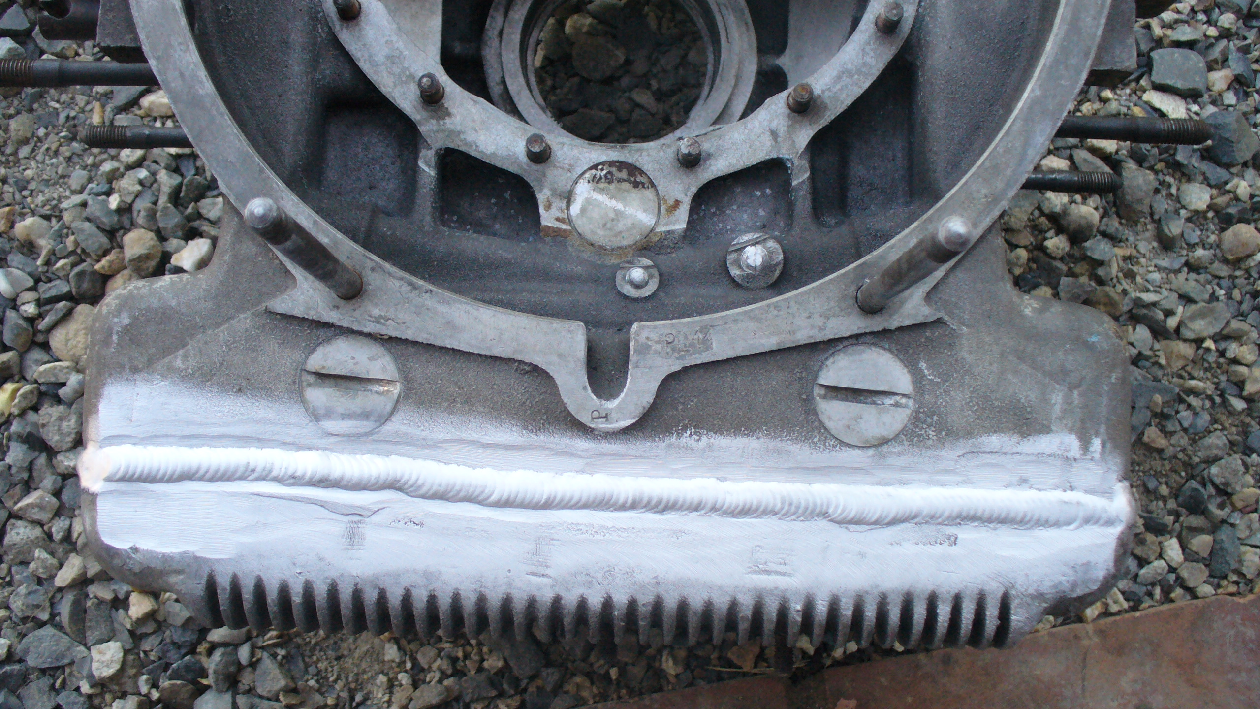
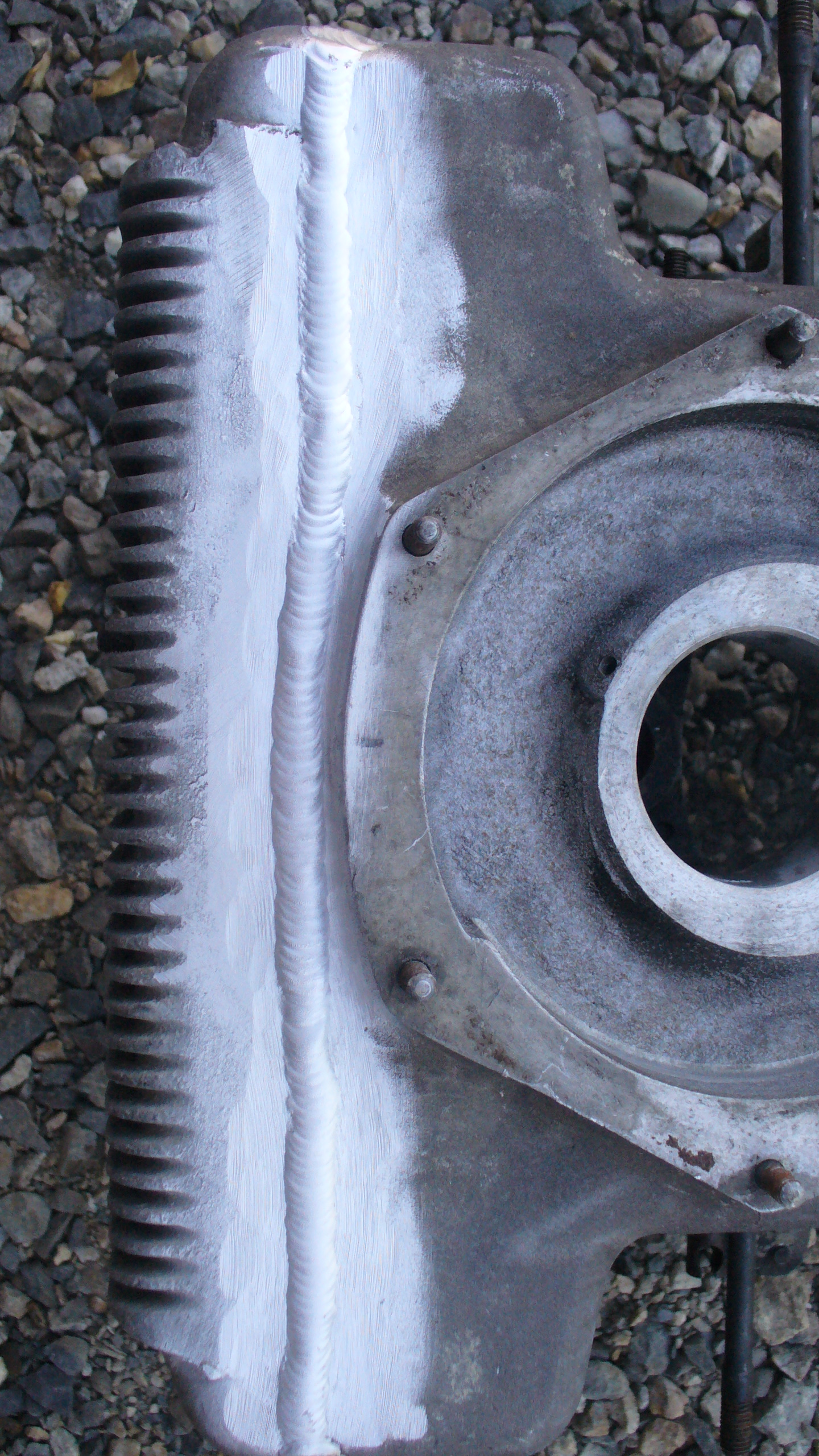
How you do this is down to the individual, one resourceful chap aka yves31 submitted these photos on the forumpanhard.free.fr. If you look closely, he has removed a thin portion off the base of his existing engine, taken another engine, and removed the sump with a higher cut line, and TIG welded the two together. All of this adds 21mm to the depth, and gives 1.3 litres of extra capacity. It is an excellent idea, but probably not easily achieved by typical owners, needs a donor crankcase, some skilful welding and requires a total stripdown of the engine. The last point is only valid if you have an engine in good condition.
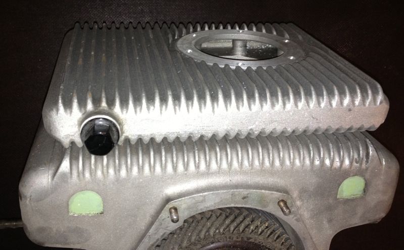
The next way, is to take a leaf out of the competition engines of the 1950’s and fit a double sump or double carter. The beauty of this system is it is easily fitted, has more surface area, yet still adds about 1.1 litres of extra oil, and can be purchased for around €140, without the oil pump adapters. This is the system that I fitted to Ron Tyrrell’s car, along with a modified oil filter kit, that placed the filter inside the crankcase, and not externally, like my other versions, which meant the extra depth of the sump (44mm) was about the same as the screw on oil filter conversion.
In tests, the oil temperature of his car dropped significantly around town, rarely went above 80ºC in drives around the rural roads. In motorway work this summer on the way to the Citröen Rally at Harrogate where 130ºC had been seen in the sump previously, the temperature never went above 115ºC, and once the ignition timing and fuelling had been dialled in, the car was travelling faster and only recording 105ºC in the sump. Another observation was, as the car was being used the oil temperature rose more slowly than before, and also recovered, whereas I seem to remember in a fateful journey to Worcester one year in the same car (without the sump addition) as the day got warmer, the temperatures kept getting hotter, until a valve seat let go.
This reinforces the best way to cool the engine is with more oil capacity, however fitting an oil cooler has other benefits in that it can be used as a heating matrix for demisting & added warmth without the oily whiffs off the air fed heating system at present.
One of the problems some Panhard owners have with filtration is the ground clearance issue, which is really is a non issue on Dyna X, PL17 & 24 models, because the exhausts hang down further either side of the sump plate, where typically an aftermarket filter is located. If adding a double sump or anything else it would be best to fit an internal filter, with the flatter sump plate, and although filter changes are not as quick, if ground clearance is an issue to the owner, an internal filter would be the best option.
Over the next few months I will be making a revised internal filter kit for the double sump variant, based on the Ron Tyrrell prototype, as Brian’s engine needs one and so does a friend in Belgium, but I am just rejigging the CAD files, as this latest double sump, has a smaller hole on the underside than previously. Ideally, I’d like to make one new sump plate fit both versions, but even though it would compromise the ground clearance by only 13mm, it’s probably better to make two different versions to negate criticism.
Filtration is required because roller bearings have much less tolerance to particulates & contamination than the more widely used shell bearings, and fortunately tor Panhard owners there are various alternatives out there. Mr Guny and myself have developed suction variants, and later Mr Lauffenburger developed his pressure fed system. The latter is a comprehensive upgrade, and includes a new oil pump, the option to fit oil coolers and various other sensors.
It really doesn’t matter which one is used, as long as you employ some type of filtration. Historically, Panhard did fit a positive pressure filter off the RJH banjo feeds of the cylinders, but it was a partial system, because once the RJH system got up to pressure the main oil flow was through the camshaft gallery bypassing this arrangement.
Why did Mr Guny & myself both go down the suction route? I’d like to think we both recognised the oil flow of the Panhard engine is so low (compared to modern engines), that the pressure drop across a paper filter is negligible, and not a problem for the oil pump. This can be quite hard for people to understand, especially when surrounded by modern engines and all the technobabble that they are exposed to, but the simple fact is the Panhard engine is a low flow device, really elegantly designed, and it’s only when you start to use the engine harder in modern traffic conditions that the system gets stretched, and mainly because the oil gets too hot.
Again, there is a school of thought which says you should use OEM oils in your car even 50 years later, well that is nonsense. Do you think oil technology has stood still in that time, so don’t expect your engine to suffer the old stuff either. In todays driving conditions, on a summers day going down the motorway, you will exceed the oil temperature limits of straight mineral oil frequently, however around town stuck in traffic with little airflow only occasionally.
What does this tell you? Simply, the engine cannot dissipate the heat in the oil. So how to do something about this? Heat dissipated is proportional to the flow rate, the surface area available, and also the quantity, because a small kettle boils faster than a big one. The complicated way (and not dissing anyone) is fit an oil cooler (more surface area), and a bigger oil pump and tackle the flow side of the equation, but the really smart option is to increase the oil capacity.
How you do this is down to the individual, one resourceful chap aka yves31 submitted these photos on the forumpanhard.free.fr. If you look closely, he has removed a thin portion off the base of his existing engine, taken another engine, and removed the sump with a higher cut line, and TIG welded the two together. All of this adds 21mm to the depth, and gives 1.3 litres of extra capacity. It is an excellent idea, but probably not easily achieved by typical owners, needs a donor crankcase, some skilful welding and requires a total stripdown of the engine. The last point is only valid if you have an engine in good condition.
The next way, is to take a leaf out of the competition engines of the 1950’s and fit a double sump or double carter. The beauty of this system is it is easily fitted, has more surface area, yet still adds about 1.1 litres of extra oil, and can be purchased for around €140, without the oil pump adapters. This is the system that I fitted to Ron Tyrrell’s car, along with a modified oil filter kit, that placed the filter inside the crankcase, and not externally, like my other versions, which meant the extra depth of the sump (44mm) was about the same as the screw on oil filter conversion.
In tests, the oil temperature of his car dropped significantly around town, rarely went above 80ºC in drives around the rural roads. In motorway work this summer on the way to the Citröen Rally at Harrogate where 130ºC had been seen in the sump previously, the temperature never went above 115ºC, and once the ignition timing and fuelling had been dialled in, the car was travelling faster and only recording 105ºC in the sump. Another observation was, as the car was being used the oil temperature rose more slowly than before, and also recovered, whereas I seem to remember in a fateful journey to Worcester one year in the same car (without the sump addition) as the day got warmer, the temperatures kept getting hotter, until a valve seat let go.
This reinforces the best way to cool the engine is with more oil capacity, however fitting an oil cooler has other benefits in that it can be used as a heating matrix for demisting & added warmth without the oily whiffs off the air fed heating system at present.
One of the problems some Panhard owners have with filtration is the ground clearance issue, which is really is a non issue on Dyna X, PL17 & 24 models, because the exhausts hang down further either side of the sump plate, where typically an aftermarket filter is located. If adding a double sump or anything else it would be best to fit an internal filter, with the flatter sump plate, and although filter changes are not as quick, if ground clearance is an issue to the owner, an internal filter would be the best option.
Over the next few months I will be making a revised internal filter kit for the double sump variant, based on the Ron Tyrrell prototype, as Brian’s engine needs one and so does a friend in Belgium, but I am just rejigging the CAD files, as this latest double sump, has a smaller hole on the underside than previously. Ideally, I’d like to make one new sump plate fit both versions, but even though it would compromise the ground clearance by only 13mm, it’s probably better to make two different versions to negate criticism.
Panhard Oil Light Piston
Saturday 02 February 2013
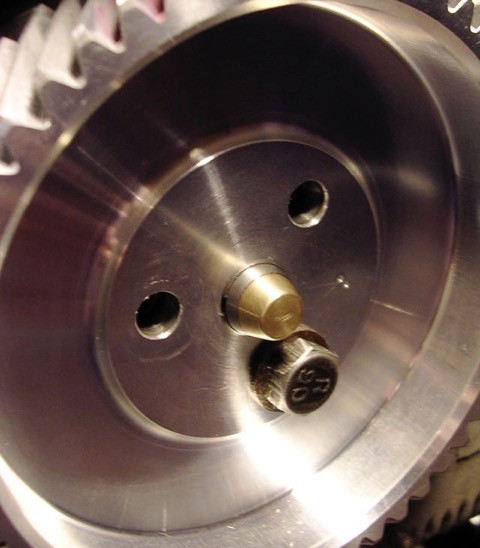
I have been asked to make an oil light piston for a friend in Belgium, and as promised here it is. This is only used when you modify the crankcase oil circuits, and although it is of similar dimensions to the OEM part, there is a built in oil pressure relief valve that only dumps oil through the side drilling to the timing gears when the camshaft gallery has a minimum of 30 psi or 2 bar pressure.
The diameter of the side drilling can be increased, but at the moment, there appears to be sufficient lubrication to the timing gears.
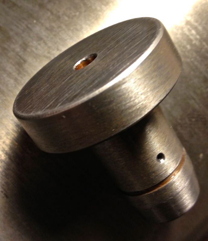
The circlip is not fitted in the following pic, and I haven’t rounded the corners at the tip. The evidence so far is it isn’t needed, but you can do this if you want.
The diameter of the side drilling can be increased, but at the moment, there appears to be sufficient lubrication to the timing gears.
The circlip is not fitted in the following pic, and I haven’t rounded the corners at the tip. The evidence so far is it isn’t needed, but you can do this if you want.
Panhard external oil filter conversion - screw on filter update
Wednesday 02 January 2013
A lot of time has gone by since I did my first oil filter conversion, the first ten kits used a Champion F129 filter, whereas the later ones had a different thread and used a M20 x 1.5mm Renault Purflux filter.
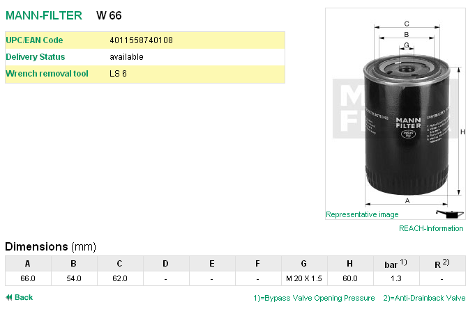
At the time the economics of making a special filter for the cars was out of the question, so it was necessary to remove the anti drain valve membrane fitted to the Purflux aka Renault Clio unit. Later on I made an internal filter version, but when I made a few external filter kits later I used a Mann Hummel W66. Details as below, but the picture is not representational, as it is only 60mm high. It is fitted with a bypass valve, which allows oil to flow should the filter clog up sufficiently to restrict the oil flow, but this is only really needed in high flow shell bearing crankshafts. In the Panhard engine, the low flow requirements and the low mileage usage they see means that the oil and filter would be changed before the bypass valve could operate, and besides the oil light would illuminate more frequently if this was happening.
One of the areas that was an improvement on the very first filter kit design was the dished area of the sump plate that received the filter cartridge was increased, so that meant there was more scope for larger diameter screw on filters.
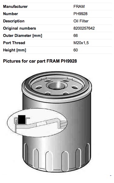
A UK PL17 owner, Gary Ockenden, who is involved in the motor trade recommended a Fram 9928, which is shown below (the picture is not representational), and this is an alternative for the Purflux LS924 & Mann Hummel W66.
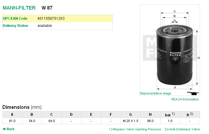
Another filter that can be used is a Mann Hummel W87, but this is some 26mm taller than the W66.
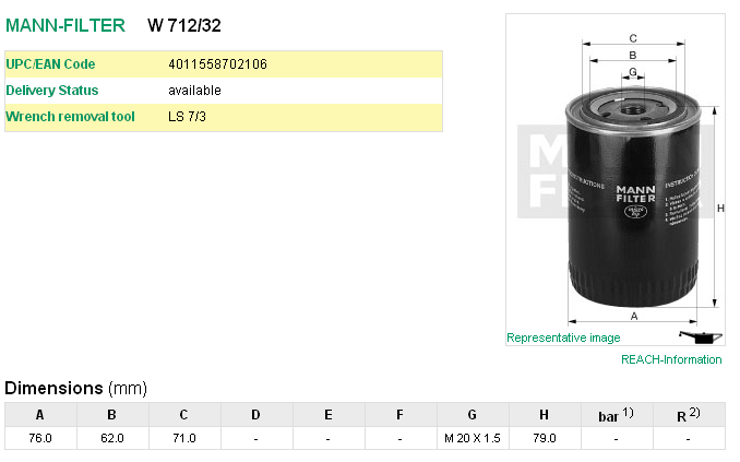
However the best filter, which has no bypass valve or anti drain valve fitted, so it is ideal on the suction side, is the Mann Hummel W712/32, but this is slightly taller by 19mm over the W66, and so better suited to the PL17 models. This model has a larger diameter as well, and so holds more oil.
The Mann 712/32 filter is also cross referenced to these numbers.
Ford 5022 739
Opel 650386
Vauxhall VOF114
GM 93156652 or 93156659
At the time the economics of making a special filter for the cars was out of the question, so it was necessary to remove the anti drain valve membrane fitted to the Purflux aka Renault Clio unit. Later on I made an internal filter version, but when I made a few external filter kits later I used a Mann Hummel W66. Details as below, but the picture is not representational, as it is only 60mm high. It is fitted with a bypass valve, which allows oil to flow should the filter clog up sufficiently to restrict the oil flow, but this is only really needed in high flow shell bearing crankshafts. In the Panhard engine, the low flow requirements and the low mileage usage they see means that the oil and filter would be changed before the bypass valve could operate, and besides the oil light would illuminate more frequently if this was happening.
One of the areas that was an improvement on the very first filter kit design was the dished area of the sump plate that received the filter cartridge was increased, so that meant there was more scope for larger diameter screw on filters.
A UK PL17 owner, Gary Ockenden, who is involved in the motor trade recommended a Fram 9928, which is shown below (the picture is not representational), and this is an alternative for the Purflux LS924 & Mann Hummel W66.
Another filter that can be used is a Mann Hummel W87, but this is some 26mm taller than the W66.
However the best filter, which has no bypass valve or anti drain valve fitted, so it is ideal on the suction side, is the Mann Hummel W712/32, but this is slightly taller by 19mm over the W66, and so better suited to the PL17 models. This model has a larger diameter as well, and so holds more oil.
The Mann 712/32 filter is also cross referenced to these numbers.
Ford 5022 739
Opel 650386
Vauxhall VOF114
GM 93156652 or 93156659
Panhard oil filter variants
Sunday 01 July 2012
I was updating a few pages and noticed that one of the oil filter prototypes was wrongly labelled. I was doing a retrospective update after finding some photos on another MacBook, when something didn’t add up, and it turned out that I’d been investigating an internal filter variant, as the modified Renault Purflux filters were being discontinued. At this point in time, there were not many alternatives out there, so I was experimenting with internal paper cartridge filters, that I had seen in a local motor factor, and I made a prototype based on my original baseplate.
However with hindsight, it was a red herring, because a few weeks later I found a Mann Hummel external filter, that was better than the Purflux derived Renault unit, but the internal solution still has merit, especially in a double sump increased oil capacity format, which is a necessity to reduce the engine oil temperatures and increase the oil quality.
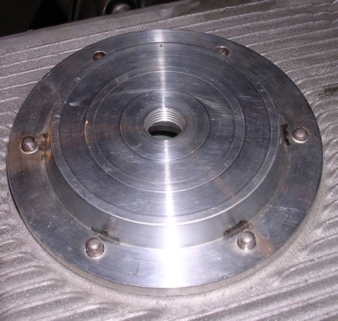
After looking at this some more, I have decided to remanufacture this variant, as it offers a different solution for the factory Panhard car, and can be used with double sump versions too. It does not hang down as far as the cartridge, which is important because the ground clearance under the engine is reduced by 50mm after fitting the factory double sump. The actual ground clearance doesn’t change however, but fitting a sump or a cartridge filter appears to lower it in some peoples’ eyes.
Further plus points are, a magnetic sump plug can also be incorporated into the sump plate if required, the filter is freely available from motor factors in Europe, and the oil filter cartridge doesn’t need to be modified, which simplifies things further for the less dextrous. Technically it’s also easier for people to understand, as the paper filter is a straight swap for the original mesh filter, although the low flow rate & low pressure drop through a paper element principle still applies.
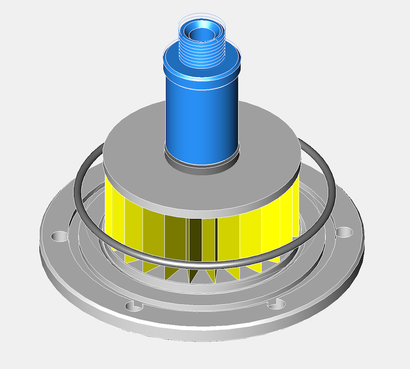
Latest CAD shown below, but it’s work in progress.
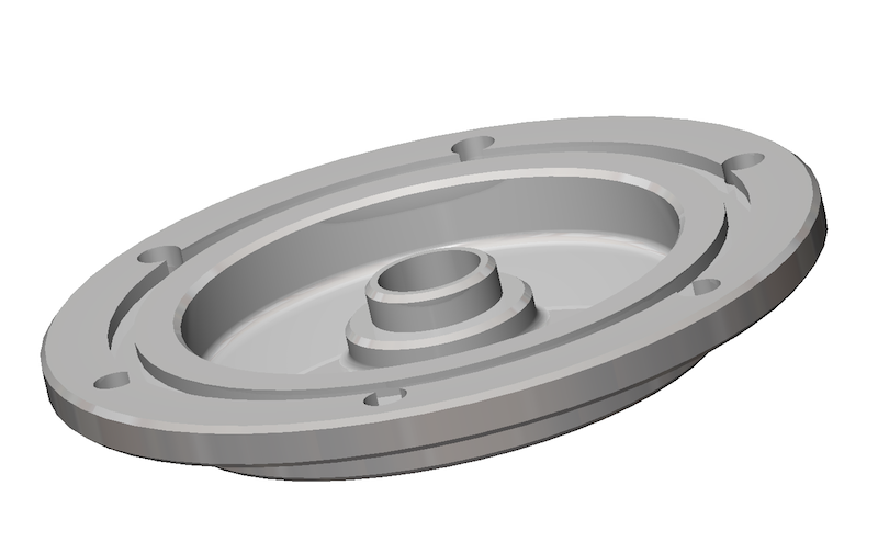
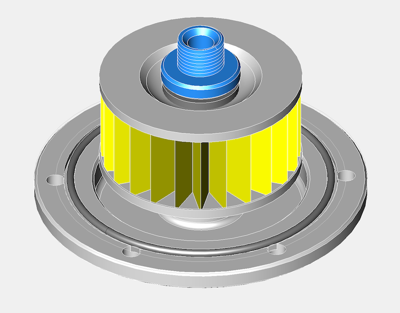
As I have been looking at the double sump variant for Brian Osbourne’s latest engine, it’s logical to try and use some of this for the next generation solution. I don’t have a double pump available at the moment, otherwise I would check whether I could use this new sump plate for the internal filter version with the double pump double sump application. I do know somebody with one, so I am going to take an internal filter and sump plate to their engine and see what is required, but it will have to wait until after the International Citröen Car Club 2012 Rally at Harrogate.
Latest thoughts in CAD for the double sump version, but only using the original oil pump, which is more than adequate assuming the crankcase oil circuits are modified. This version has a different pick up pipe and a flat not dished sump plate, so it will need two new parts.
However with hindsight, it was a red herring, because a few weeks later I found a Mann Hummel external filter, that was better than the Purflux derived Renault unit, but the internal solution still has merit, especially in a double sump increased oil capacity format, which is a necessity to reduce the engine oil temperatures and increase the oil quality.
After looking at this some more, I have decided to remanufacture this variant, as it offers a different solution for the factory Panhard car, and can be used with double sump versions too. It does not hang down as far as the cartridge, which is important because the ground clearance under the engine is reduced by 50mm after fitting the factory double sump. The actual ground clearance doesn’t change however, but fitting a sump or a cartridge filter appears to lower it in some peoples’ eyes.
Further plus points are, a magnetic sump plug can also be incorporated into the sump plate if required, the filter is freely available from motor factors in Europe, and the oil filter cartridge doesn’t need to be modified, which simplifies things further for the less dextrous. Technically it’s also easier for people to understand, as the paper filter is a straight swap for the original mesh filter, although the low flow rate & low pressure drop through a paper element principle still applies.
Latest CAD shown below, but it’s work in progress.
As I have been looking at the double sump variant for Brian Osbourne’s latest engine, it’s logical to try and use some of this for the next generation solution. I don’t have a double pump available at the moment, otherwise I would check whether I could use this new sump plate for the internal filter version with the double pump double sump application. I do know somebody with one, so I am going to take an internal filter and sump plate to their engine and see what is required, but it will have to wait until after the International Citröen Car Club 2012 Rally at Harrogate.
Latest thoughts in CAD for the double sump version, but only using the original oil pump, which is more than adequate assuming the crankcase oil circuits are modified. This version has a different pick up pipe and a flat not dished sump plate, so it will need two new parts.
Panhard crankcase rear bearing support
Saturday 10 March 2012
I was going to remove the rear NU209 main bearing on the engine, but needed to make a small adaptor to measure the end float on the crankshaft before I do so. This particular engine has a little bit of movement in the rear crank pin, and I need to find out why it has moved.
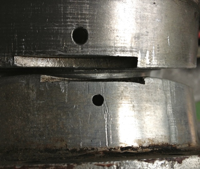
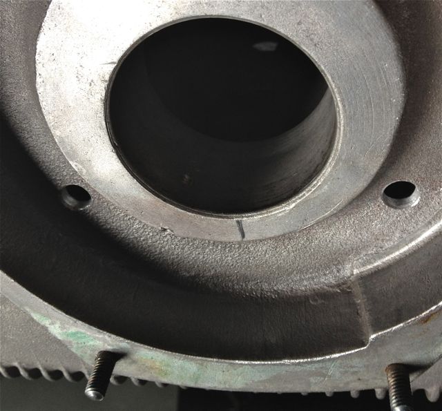
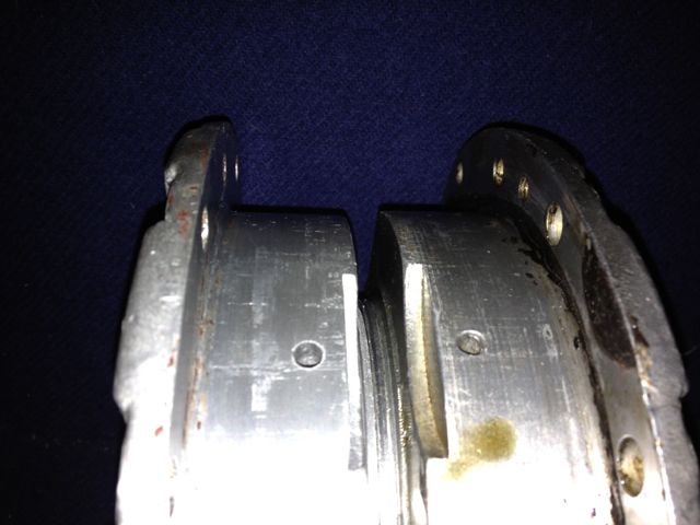
Historically the engines have had gradual tweaks over their lifetime, and the rear main bearing support plate which bolts to the crankcase is no exception. The first ones were aluminium, and the later ones were cast iron with a flexible lipped seal, as opposed to a steel piston ring. Oil starvation and inadequate capacity have always been an issue, as the cars were introduced to the ever increasing demands of modern day traffic, and I spotted another tweak today.
The early M6 back plate is on the left and the later M8 is on the right, and can you spot the difference?
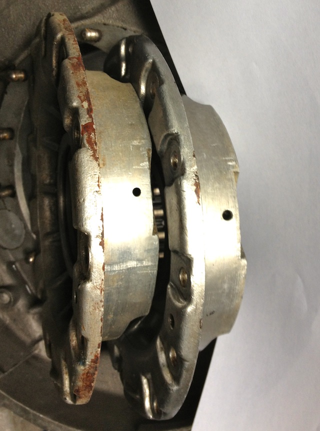
The answer is the holes are bigger on the later one, which means more oil can be supplied to the rear bearing. After measuring these it equates to an improvement of 15% over the earlier design.
Historically the engines have had gradual tweaks over their lifetime, and the rear main bearing support plate which bolts to the crankcase is no exception. The first ones were aluminium, and the later ones were cast iron with a flexible lipped seal, as opposed to a steel piston ring. Oil starvation and inadequate capacity have always been an issue, as the cars were introduced to the ever increasing demands of modern day traffic, and I spotted another tweak today.
The early M6 back plate is on the left and the later M8 is on the right, and can you spot the difference?
The answer is the holes are bigger on the later one, which means more oil can be supplied to the rear bearing. After measuring these it equates to an improvement of 15% over the earlier design.
Panhard crankcase front oil drilling modifications
Sunday 04 March 2012
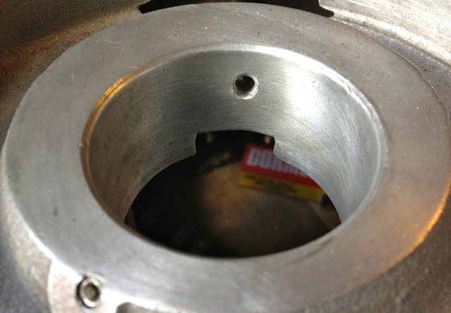
The original engines had this oil feed visible above the camshaft bore at the very front of the crankcase, which is shown below. As the camshaft rotates this drilling is filled two times per camshaft revolution, and after this it passes in a trough that is underneath the bearing and the oil jumps into the slingers. Some oil splashes back and passes through the main bearing, but the rest is accelerated by the slingers at the crank web, and passes through the big end bearing via a drilling in the crank web before exiting and splash lubricating the little end.
Unfortunately this hole is too small, and it is the cause of a 50% reduction in flow rate over the rear pro rata. There is an added complication that this hole is also 50% smaller than the rear oil feed, so there is quite a bit of reduction in potential flow rate assuming the pressures were the same. As you might have read there is a pressure difference, because of the secondary drilling that fed the camshaft timing gear on the early engines which compounded the problem , and led to reliability issues, which eventually forced an engine redesign to this area.
This can be negated by carrying out a few modifications, all of which will be documented here.
It might not be obviously apparent from this picture, but the hole size is now 6mm diameter, whereas the one above is just 4mm. This new oil feed now matches the camshaft aperture, so all openings, front and rear are timed equally. The 4mm diameter hole in the middle that is drilled presently, will have to be enlarged to 5mm to match the rear oil feed that is fed from the common camshaft oil gallery. At first it is more important to get the hole in the right position, and work from this, which is why it is now at 5mm diameter, as shown below.
This now means both front and rear oil galleries are equally phased and have the same pressure variations, as there is no mismatched timing gear oil feed anymore affecting the front oil supply. However that still leaves the task of creating a new oil feed to do this, because you didn’t think the gear was going to lubricate itself from the plain bearing leaking, but that’ll be another update.
Panhard crankcase camshaft drive gear oil level
Sunday 04 March 2012
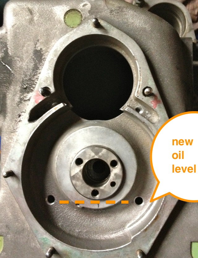
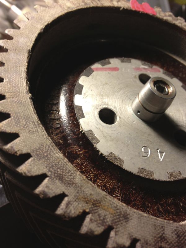
A little mod that improves oil quality, reduces heat build up in the oil, and improves pumping losses to the engine. At the moment the Panhard timing case oil level is determined by the hi level drainage points shown here or leaking past the front main bearing.
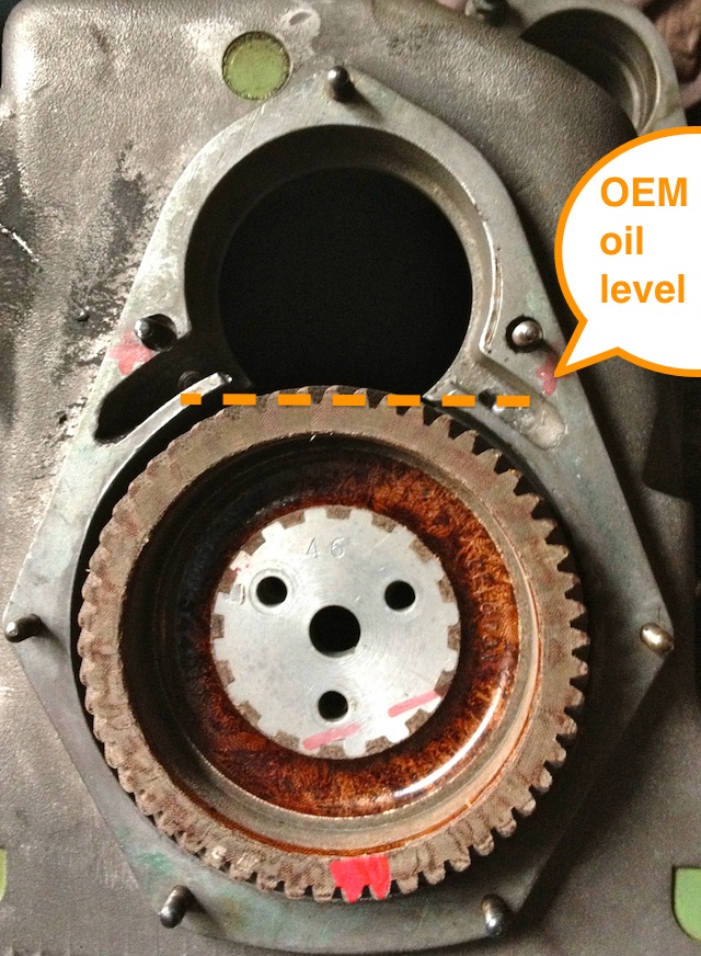
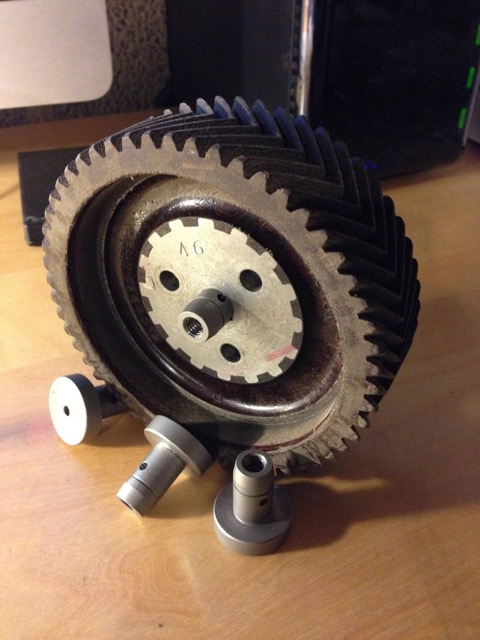
Normal practice for a splash lubricated gear is to have no more than a third of the overall gear diameter immersed, so why Panhard did this surprises me. Originally they had a fibre wheel of massive proportions meshing to a hardened steel gear, with huge gear area, and in all fairness it probably didn’t need much lubrication. If it was being made today this fibre wheel, which is often replaced by an aluminium one, could be made of a plastic material quite easily.
These new drillings, now restore the status quo, and at the same time allow for this area to get some oil changes. Technically these wouldn’t get fully drained, unless you remove the steel timing cover case, because there is no low level return point. I think it is realistic to revise this mod and lower the oil level further, but as this is the third engine I have modded in this area, I will wait until I get some better feedback before doing so.
Panhard oil pump output
Sunday 04 March 2012
I have mentioned earlier that the Panhard oil supply was designed to be a low flow, low oil pressure system, but I haven’t really explained why.
Originally the engine had a lot of roller bearings inside it, and crucially the crankshaft was suspended using these. In fact cylindrical roller bearing set ups are making a come back in engine design, especially in the USA where Timken are applying this to some current engines, to showcase the technology again, and also promote their own bearing interests. One of the reasons they are using it, is to reduce pumping losses, and the frictional drag reductions against the more common plain bearing engines, because there is an environmental need to make combustion engines more economical.
The Panhard engine was quite clever in that it used a small pump to get the oil roughly where it was needed, and then the centrifugal effect of the slingers in the crankshaft webs gave a speed related response to the engine needs. This was a good fit with the requirements of the engine, and although there was a maintenance issue with slingers clogging up, mileages were not great in the late 1940’s when the engine was being designed, and a 30,000 mile target wasn’t unreasonable. Fast forward to the 21st Century and maybe some things would be different now, and if you look at the evolution of a similar engine, the BMW R50 motorcycle, that moved from centrifugal oil supply to a cross drilled crank, and the more common one piece crankshaft & split connecting rods with plain bearings.
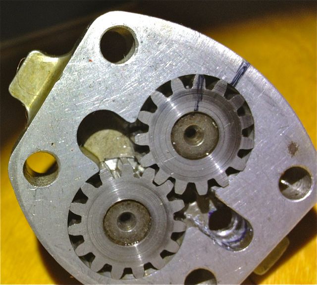
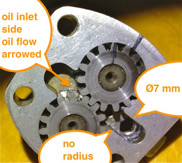
Aside from the maintenance issue with the slingers, there is nothing really wrong with the original oil pump, but if you read the history books you might be lead to believe otherwise. Here is the pump, and it is a gear type oil pump, which was a current design around the time, and it is more than adequate for the job. There are a couple of issues, that if it was being made today, that you would change, but I’ll elaborate later.The first one is, there are no rounded edges from the oil pump body into the output drilling, which is 90 degrees to it, and this will cause back pressure and cavitation, at higher oil volumes .
So if I was going to do one thing to address this, it would involve using a Dremel and doing this.
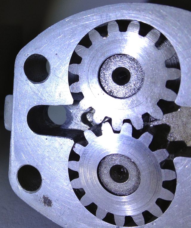
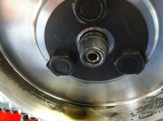
This modified oil pump will now flow more oil at speed, when you want it and there will be less bubbles in the oil as a result, which has the effect of improving the oil quality. I have successfully done this on three engines to date, and did test it out on the oil filter crankcase test rig many years ago. It is beneficial, and is one way of simply boosting the nett oil flow, but there is a bigger win win at the crankcase entry. If you were trying to maximise flow, you wouldn’t squeeze a garden hose pipe, but that’s exactly what Panhard did, because the crankcase oil inlet from the pump is 4.8mm diameter, yet the pump output is 7mm in diameter, which is almost a 50% reduction in cross sectional area. So after radiussing the outlet of the pump body there is an even bigger restriction downstream, and all the oil for the engine is fed by this small hole. It really doesn’t make sense with hindsight
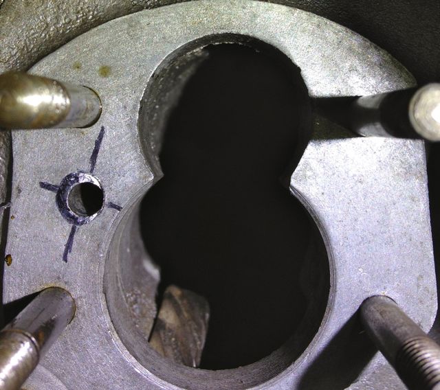
You can see the small inlet pipe into the crankcase, and also see where the oil pump mates up to it, which is the black circle I have inked in and the centre of the outlet is represented by the black lines. So again the flexible shaft is used to reshape this area, and the important thing is to match the mating diameters more closely. It makes sense to machine and open up this drilling to match the oil pump, as this will increase the flow rate into the main oil galleries, and it has no effect on the pressure of the system, contrary to what you might think. The pressure in the unmodified camshaft is controlled by the cross drilling after this, and the cylinder head feeds likewise by the size of their respective openings too.
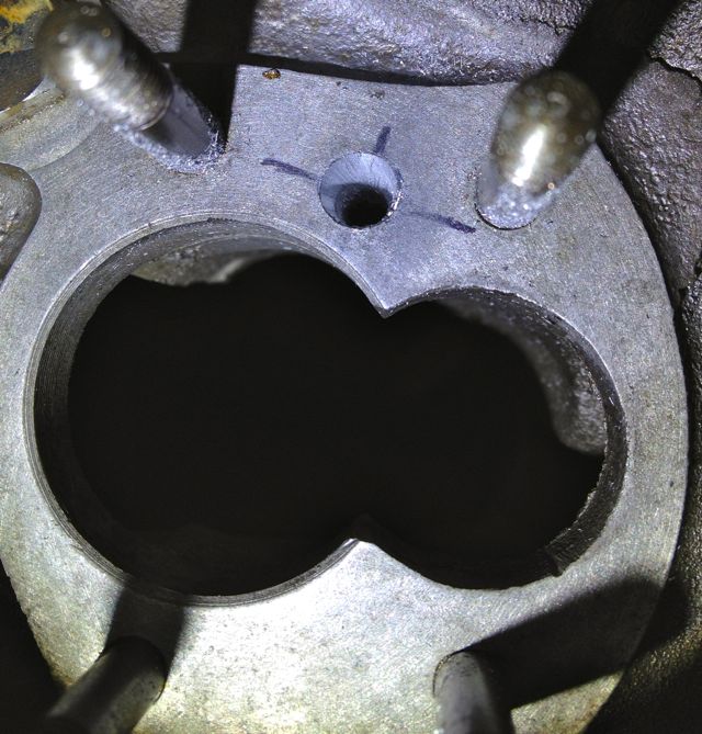
Crankcase main oil gallery modified to match oil pump outlet diameter.
Originally the engine had a lot of roller bearings inside it, and crucially the crankshaft was suspended using these. In fact cylindrical roller bearing set ups are making a come back in engine design, especially in the USA where Timken are applying this to some current engines, to showcase the technology again, and also promote their own bearing interests. One of the reasons they are using it, is to reduce pumping losses, and the frictional drag reductions against the more common plain bearing engines, because there is an environmental need to make combustion engines more economical.
The Panhard engine was quite clever in that it used a small pump to get the oil roughly where it was needed, and then the centrifugal effect of the slingers in the crankshaft webs gave a speed related response to the engine needs. This was a good fit with the requirements of the engine, and although there was a maintenance issue with slingers clogging up, mileages were not great in the late 1940’s when the engine was being designed, and a 30,000 mile target wasn’t unreasonable. Fast forward to the 21st Century and maybe some things would be different now, and if you look at the evolution of a similar engine, the BMW R50 motorcycle, that moved from centrifugal oil supply to a cross drilled crank, and the more common one piece crankshaft & split connecting rods with plain bearings.
Aside from the maintenance issue with the slingers, there is nothing really wrong with the original oil pump, but if you read the history books you might be lead to believe otherwise. Here is the pump, and it is a gear type oil pump, which was a current design around the time, and it is more than adequate for the job. There are a couple of issues, that if it was being made today, that you would change, but I’ll elaborate later.The first one is, there are no rounded edges from the oil pump body into the output drilling, which is 90 degrees to it, and this will cause back pressure and cavitation, at higher oil volumes .
So if I was going to do one thing to address this, it would involve using a Dremel and doing this.
This modified oil pump will now flow more oil at speed, when you want it and there will be less bubbles in the oil as a result, which has the effect of improving the oil quality. I have successfully done this on three engines to date, and did test it out on the oil filter crankcase test rig many years ago. It is beneficial, and is one way of simply boosting the nett oil flow, but there is a bigger win win at the crankcase entry. If you were trying to maximise flow, you wouldn’t squeeze a garden hose pipe, but that’s exactly what Panhard did, because the crankcase oil inlet from the pump is 4.8mm diameter, yet the pump output is 7mm in diameter, which is almost a 50% reduction in cross sectional area. So after radiussing the outlet of the pump body there is an even bigger restriction downstream, and all the oil for the engine is fed by this small hole. It really doesn’t make sense with hindsight
You can see the small inlet pipe into the crankcase, and also see where the oil pump mates up to it, which is the black circle I have inked in and the centre of the outlet is represented by the black lines. So again the flexible shaft is used to reshape this area, and the important thing is to match the mating diameters more closely. It makes sense to machine and open up this drilling to match the oil pump, as this will increase the flow rate into the main oil galleries, and it has no effect on the pressure of the system, contrary to what you might think. The pressure in the unmodified camshaft is controlled by the cross drilling after this, and the cylinder head feeds likewise by the size of their respective openings too.
Crankcase main oil gallery modified to match oil pump outlet diameter.
Panhard crankcase oil circulation modifications (revisited)
Saturday 03 March 2012
A quick history lesson on Panhard engine failures. The front main bearing and front cylinder crankshaft big end started to develop failures, as they increased the horsepower. It was attributed to insufficient oil supply, and so the front end lubrication was revised, and the camshaft timing gears were used as a splash lubrication system and the oil drilling that provided that role under the front main bearing was removed. This modification was introduced from around the early 1960’s, and ran to the end of production in 1967.
Unfortunately for Panhard they were barking up the wrong tree, despite the engine coming from a well thought out design originally, other people tinkered with the design knee jerk fashion as the problems developed, and nobody took an overview and look at the root causes. The financial woes and Citröen management probably didn’t help, but as Panhard died in 1967, we will never really know.
Flash forward to the next century, and if you are running one of these engines, it will almost be suffering from the result of this modification. As the engine ages the oil pump becomes more marginal, the priority oil fed valve gear bushes in the head wear, and the oil into the camshaft gallery reduces. Now the front bearings don’t really fatigue like they used to, but the rears suffer because they are pump related. So the problem has transferred itself, and the question that should be asked is why?
Of course if you look at the development of these engines you will read about the engines modified for endurance racing, which had higher capacity pumps, and an increased oil capacity with the fitment of an additional sump, that also acted as a baffled cavity for the oil pick up pipe. This subset of development has been an evolutionary branch of Panhard engine that needs revising, because if you really look at the problem, these solutions are papering over the cracks of a design fault. If you go back in time, and look at the engine design of the Panhard flat twin compared to others, there are numerous good points taken from lots of influences. The crankshaft oil supply is reminiscent of Bugatti & the early BMW motorcycle engines, but it is essentially a low pressure system, and even the design of the original plain bearing surfaces reflect this, so why fit a higher pressure set up, but that’s another story.
For example in the front bearing of the camshaft, which has a very large diameter at the front where the timing gear is driven by the crankshaft, and a more normal sized bearing diameter at the rear. Also, if you look at the oil drillings that feed these plain bearings, they are proportionately scaled to suit. The camshaft is the common denominator in all of this because it is one of three main oil feeds from the oil pump, and the supply conduit for the front and rear main bearings and the crankshaft lubrication, but wasn’t there a problem here?
So how can a central oil gallery that feeds both the front and rear crankshafts be at fault? Actually, the central gallery is not the problem, because the flow into this is separate from the outputs, and if you look at these, the problem is almost explained. The original designer knew he needed to equalise the distribution of the oil, so the oil outputs for the front and rear crankshaft feeds are phased to do just this, and as the cross drillings are on a rotating surface the timing window on the camshafts are scaled accordingly. However, although the rear crankshaft oil drilling is sized to match the rear camshaft drilling, the front is mismatched, because the oil drilling in the crankcase is too small.
On examination the oil drilling needs to be around 6mm diameter, when it is only 4mm, which is a 50% reduction in oil supply compared to the rear, and this alone would explain the front end failure susceptibility, but it doesn’t end there. The original designer tried to phase the oil supply to the front and rear ends equally, but somebody else decided the camshaft timing gear at the front should have some more lubrication, and put in an additional drilling. The reality was that the original plain bearing would have leaked into this cavity, and as there were no low level drainage holes, the oil wouldn’t go away, so it really didn’t need the additional drilling, but the biggest problem was where it was positioned. The oil pump doesn’t need to be big, as the engine only needed low flow rates and low pressure to work within it original design specifications, however any pressure drop say after a drilling would take a little time to recover, and this was accepted in the design layout, but as soon as the oil drilling to the front timing gear was placed ahead of the front end oil supply, the 50% reduction in flow rate all things being equal just got worse, as this drilling lost pressure after 60 degrees of a 90 degree recovery window, and only gave the camshaft 30 degrees to recover the oil pressure in the gallery. This means the front crankshaft oil feeds are compromised further, whereas the rears are unaffected, and it was all down to a simple production oversight.
What is the solution? Again, a quick history lesson will tell you all you need to know, and it is the route of many flat twin Panhard devotees, but don’t bother looking at the history books, what you have to do is engine specific, but that’ll be for another day. Suffice to say, I spotted this many years ago, and have been making parts and modding a few engines to overcome these oil related faults every time I get hold of one.
A quick walkthrough of what to do
1. Mod the oil pump
2. Mod the crankcase oil circuits, two different methods for the M6 & M10 engines.
3. Make a new oil light piston or buy one from me
1. Modify the oil pump
Originally the engine had a lot of roller bearings inside it, and crucially the crankshaft was suspended using these. In fact cylindrical roller bearing set ups are making a come back in engine design, especially in the USA where Timken are applying this to some current engines, to showcase the technology again, and also promote their own bearing interests. One of the reasons they are using it, is to reduce pumping losses, and the frictional drag reductions against the more common plain bearing engines, because there is an environmental need to make combustion engines more economical.
The Panhard engine was quite clever in that it used a small pump to get the oil roughly where it was needed, and then the centrifugal effect of the slingers in the crankshaft webs gave a speed related response to the engine needs. This was a good fit with the requirements of the engine, and although there was a maintenance issue with slingers clogging up, mileages were not great in the late 1940’s when the engine was being designed, and a 30,000 mile target wasn’t unreasonable. Fast forward to the 21st Century and maybe some things would be different now, and if you look at the evolution of a similar engine, the BMW R50 motorcycle, that moved from centrifugal oil supply to a cross drilled crank, and the more common one piece crankshaft & split connecting rods with plain bearings.
Aside from the maintenance issue with the slingers, there is nothing really wrong with the original oil pump, but if you read the history books you might be lead to believe otherwise. Here is the pump, and it is a gear type oil pump, which was a current design around the time, and it is more than adequate for the job. There are a couple of issues, that if it was being made today, that you would change, but I’ll elaborate later.The first one is, there are no rounded edges from the oil pump body into the output drilling, which is 90 degrees to it, and this will cause back pressure and cavitation, at higher oil volumes .
So if I was going to do one thing to address this, it would involve using a Dremel and doing this.
This modified oil pump will now flow more oil at speed, when you want it and there will be less bubbles in the oil as a result, which has the effect of improving the oil quality. I have successfully done this on three engines to date, and did test it out on the oil filter crankcase test rig many years ago. It is beneficial, and is one way of simply boosting the nett oil flow, but there is a bigger win win at the crankcase entry. If you were trying to maximise flow, you wouldn’t squeeze a garden hose pipe, but that’s exactly what Panhard did, because the crankcase oil inlet from the pump is 4.8mm diameter, yet the pump output is 7mm in diameter, which is almost a 50% reduction in cross sectional area. So after radiussing the outlet of the pump body there is an even bigger restriction downstream, and all the oil for the engine is fed by this small hole. It really doesn’t make sense with hindsight
You can see the small inlet pipe into the crankcase, and also see where the oil pump mates up to it, which is the black circle I have inked in and the centre of the outlet is represented by the black lines. So again the flexible shaft is used to reshape this area, and the important thing is to match the mating diameters more closely. It makes sense to machine and open up this drilling to match the oil pump, as this will increase the flow rate into the main oil galleries, and it has no effect on the pressure of the system, contrary to what you might think. The pressure in the unmodified camshaft is controlled by the cross drilling after this, and the cylinder head feeds likewise by the size of their respective openings too.
Crankcase main oil gallery modified to match oil pump outlet diameter.
2. Modify the crankcase (M10S version below)
This engine is the later type, so needs modifying back to the original oil supply route, but adding the improvements necessary to negate the other faults. The first area to tackle is the front end crankshaft oil supply, so plugging the newer oil drillings and creating a matched new one under the front main bearing housing. These will be fixed with Loctite once all the drilling has finished and the crankcase has been thoroughly cleaned.
I will reduce the oil level & flow in the timing gear casing, so reduce pumping losses, and oil degradation. On examination the deposits in the slingers at the front part of the crankshaft were almost double those at the rear, which is mainly due to the oil supply being much greater to the front and also the timing gear casing is a stale oil residue trap. Once contaminated here, the particulates have no option but return via the main bearing aperture, and then be centrifuged in the front slinger and as there is no drain out of this area, the oil is never fully refreshed.
I have to modify the later style crankcase to adjust the oil circulation. This will mean creating a new big end feed under the front main bearing, plugging some of the existing galleries, and making new drain holes for the front timing gear. This will reduce pumping losses, lower oil temperatures and improve oil quality.
At the moment the Panhard timing case oil level is determined by the high level drainage points shown here or leaking past the front main bearing. In reality the OEM oil level never reaches this height, because the gears act like a huge waterwheel and churn through the bearing, but this still causes parasitic losses, and the modded race cars aka DBs, used a modified timing gear to overcome this.
Normal practice for a splash lubricated gear is to have no more than a third of the overall gear diameter immersed, so why Panhard did this surprises me. Originally they had a fibre wheel of massive proportions meshing to a hardened steel gear, with huge gear area, and in all fairness it probably didn’t need much lubrication. If it was being made today this fibre wheel, which is often replaced by an aluminium one, could be made of a plastic material quite easily.
These new drillings, now restore the status quo, and at the same time allow for this area to get some oil changes. Technically these wouldn’t get fully drained, unless you remove the steel timing cover case, because there is no low level return point. I think it is realistic to revise this mod and lower the oil level further, but as this is the third engine I have modded in this area, I will wait until I get some better feedback before doing so.
Now to mod the front crankshaft oil feed.
The later engines didn’t have this option, as can be seen here.

The original engines had this oil feed visible above the camshaft bore at the very front of the crankcase, which is shown below. As the camshaft rotates this drilling is filled two times per camshaft revolution, and after this it passes in a trough that is underneath the bearing and the oil jumps into the slingers. Some oil splashes back and passes through the main bearing, but the rest is accelerated by the slingers at the crank web, and passes through the big end bearing via a drilling in the crank web before exiting and splash lubricating the little end.
Unfortunately this hole is too small, and it is the cause of a 50% reduction in flow rate over the rear pro rata. There is an added complication that this hole is also 50% smaller than the rear oil feed, so there is quite a bit of reduction in potential flow rate assuming the pressures were the same. As you might have read there is a pressure difference, because of the secondary drilling that fed the camshaft timing gear on the early engines which compounded the problem , and led to reliability issues, which eventually forced an engine redesign to this area.
This can be negated by carrying out a few modifications, all of which will be documented here.
It might not be obviously apparent from this picture, but the hole size is now 6mm diameter, whereas the one above is just 4mm. This new oil feed now matches the camshaft aperture, so all openings, front and rear are timed equally. The 4mm diameter hole in the middle that is drilled presently, will have to be enlarged to 5mm to match the rear oil feed that is fed from the common camshaft oil gallery. At first it is more important to get the hole in the right position, and work from this, which is why it is now at 5mm diameter, as shown below.
Timing gear oil drilling plugged as shown below
Plugging this drilling means both front and rear oil galleries are now equally phased and have the same pressure variations, as there is no mismatched timing gear oil feed anymore affecting the front oil supply. However that still leaves the task of creating a new oil feed to do this, because you didn’t think the gear was going to lubricate itself from the plain bearing leaking.
3. Make a new oil light piston or buy one from me!
To lubricate the camshaft gear I made some oil light pistons to replace the standard machined cast originals shown in the bottom picture.
This is the raw machined unit, it still needs a little more work. This new oil light piston has an integral relief valve built in, essentially, a ball spring and locking screw, and I set it at 2 bar or 30psi, but you can set this to whatever you want, and even increase the oil drilling if you want to make it larger.
The importance of this is that the original oil supply will now feed the cylinder heads and the hydraulic valve adjusters first as normal, then the front and rear bearings, and only then squirt oil into the timing gear when more pressure is reached. It also means that after the oil has fed the cylinder heads, the front and rear bearings get a much better oil supply.
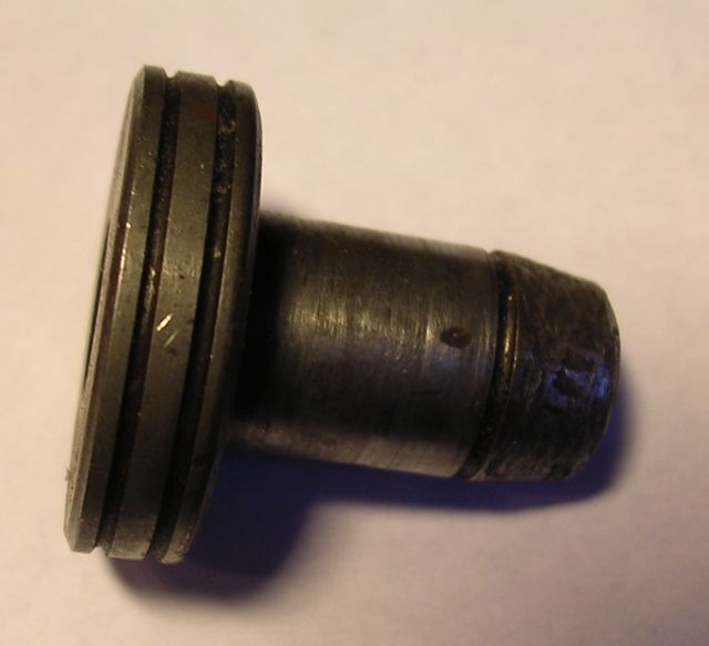
The original had a rounded tip, whereas mine had a threaded hole, which was part of the oil relief valve assembly, and I couldn’t really alter this unless I made a two part piston.
There was a concern that this nosing or tip, despite being rounded similar to the picture below …
… would still abrade the oil light wooden button, and cause problems further down the line. In real usage it has no impact, but I did make a modified version for engine number 3 some years ago, which I believe isn’t necessary now.
So we have almost finished, just need to tweak the rear bearing oil supply...
Historically the engines have had gradual tweaks over their lifetime, and the rear main bearing support plate which bolts to the crankcase is no exception. The first ones were aluminium, and the later ones were cast iron with a flexible lipped seal, as opposed to a steel piston ring. Oil starvation and inadequate capacity have always been an issue, as the cars were introduced to the ever increasing demands of modern day traffic, and I spotted another tweak today.
The early M6 back plate is on the left and the later M8 is on the right, and can you spot the difference?
The answer is the holes are bigger on the later one, which means more oil can be supplied to the rear bearing. After measuring these it equates to an improvement of 15% over the earlier design.
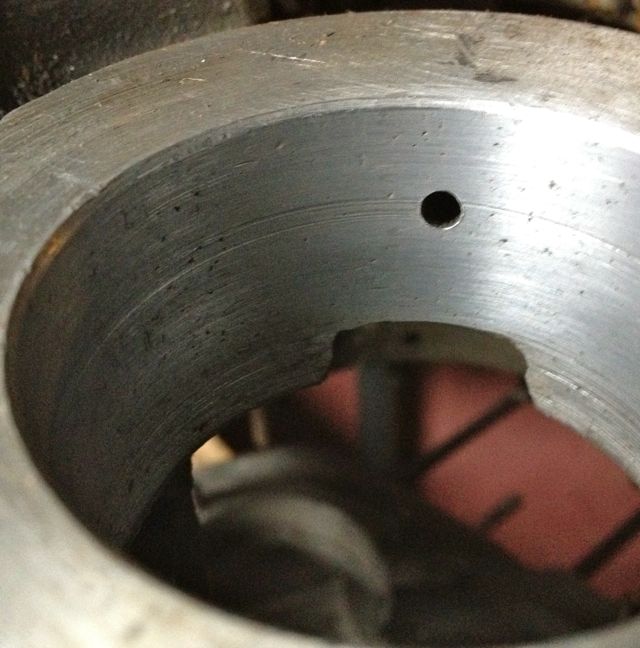
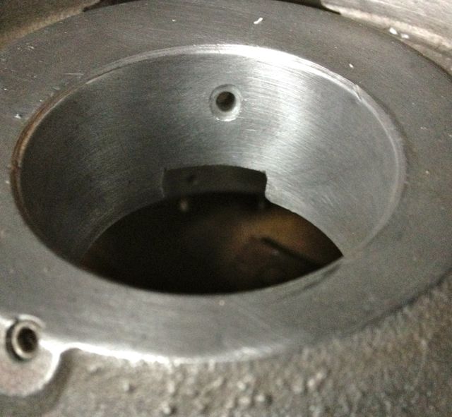
This hole needs to be bigger to reduce the cavitation and back pressure, and also equalise the flow with the improved front bearing oil supply.

This is the left hand M6 casting after being modded at the inlet side, and the outlet must be modded too. Again the change of direction gets a smoothing radius on the inside corner.
.
The hole has been smoothed and with a dummy bearing fitted you can see the difference in surface area, versus the older design underneath. What is not apparent is the hole is only 3mm in diameter just under the bearing on this M6 casting.
So that’s it. They are a few other tweaks that can be made, but modifying the oil circuits this way will improve a standard Panhard engine, and increase its reliability, especially if you dilter the oil and increase the sump capacity.
Unfortunately for Panhard they were barking up the wrong tree, despite the engine coming from a well thought out design originally, other people tinkered with the design knee jerk fashion as the problems developed, and nobody took an overview and look at the root causes. The financial woes and Citröen management probably didn’t help, but as Panhard died in 1967, we will never really know.
Flash forward to the next century, and if you are running one of these engines, it will almost be suffering from the result of this modification. As the engine ages the oil pump becomes more marginal, the priority oil fed valve gear bushes in the head wear, and the oil into the camshaft gallery reduces. Now the front bearings don’t really fatigue like they used to, but the rears suffer because they are pump related. So the problem has transferred itself, and the question that should be asked is why?
Of course if you look at the development of these engines you will read about the engines modified for endurance racing, which had higher capacity pumps, and an increased oil capacity with the fitment of an additional sump, that also acted as a baffled cavity for the oil pick up pipe. This subset of development has been an evolutionary branch of Panhard engine that needs revising, because if you really look at the problem, these solutions are papering over the cracks of a design fault. If you go back in time, and look at the engine design of the Panhard flat twin compared to others, there are numerous good points taken from lots of influences. The crankshaft oil supply is reminiscent of Bugatti & the early BMW motorcycle engines, but it is essentially a low pressure system, and even the design of the original plain bearing surfaces reflect this, so why fit a higher pressure set up, but that’s another story.
For example in the front bearing of the camshaft, which has a very large diameter at the front where the timing gear is driven by the crankshaft, and a more normal sized bearing diameter at the rear. Also, if you look at the oil drillings that feed these plain bearings, they are proportionately scaled to suit. The camshaft is the common denominator in all of this because it is one of three main oil feeds from the oil pump, and the supply conduit for the front and rear main bearings and the crankshaft lubrication, but wasn’t there a problem here?
So how can a central oil gallery that feeds both the front and rear crankshafts be at fault? Actually, the central gallery is not the problem, because the flow into this is separate from the outputs, and if you look at these, the problem is almost explained. The original designer knew he needed to equalise the distribution of the oil, so the oil outputs for the front and rear crankshaft feeds are phased to do just this, and as the cross drillings are on a rotating surface the timing window on the camshafts are scaled accordingly. However, although the rear crankshaft oil drilling is sized to match the rear camshaft drilling, the front is mismatched, because the oil drilling in the crankcase is too small.
On examination the oil drilling needs to be around 6mm diameter, when it is only 4mm, which is a 50% reduction in oil supply compared to the rear, and this alone would explain the front end failure susceptibility, but it doesn’t end there. The original designer tried to phase the oil supply to the front and rear ends equally, but somebody else decided the camshaft timing gear at the front should have some more lubrication, and put in an additional drilling. The reality was that the original plain bearing would have leaked into this cavity, and as there were no low level drainage holes, the oil wouldn’t go away, so it really didn’t need the additional drilling, but the biggest problem was where it was positioned. The oil pump doesn’t need to be big, as the engine only needed low flow rates and low pressure to work within it original design specifications, however any pressure drop say after a drilling would take a little time to recover, and this was accepted in the design layout, but as soon as the oil drilling to the front timing gear was placed ahead of the front end oil supply, the 50% reduction in flow rate all things being equal just got worse, as this drilling lost pressure after 60 degrees of a 90 degree recovery window, and only gave the camshaft 30 degrees to recover the oil pressure in the gallery. This means the front crankshaft oil feeds are compromised further, whereas the rears are unaffected, and it was all down to a simple production oversight.
What is the solution? Again, a quick history lesson will tell you all you need to know, and it is the route of many flat twin Panhard devotees, but don’t bother looking at the history books, what you have to do is engine specific, but that’ll be for another day. Suffice to say, I spotted this many years ago, and have been making parts and modding a few engines to overcome these oil related faults every time I get hold of one.
A quick walkthrough of what to do
1. Mod the oil pump
2. Mod the crankcase oil circuits, two different methods for the M6 & M10 engines.
3. Make a new oil light piston or buy one from me
1. Modify the oil pump
Originally the engine had a lot of roller bearings inside it, and crucially the crankshaft was suspended using these. In fact cylindrical roller bearing set ups are making a come back in engine design, especially in the USA where Timken are applying this to some current engines, to showcase the technology again, and also promote their own bearing interests. One of the reasons they are using it, is to reduce pumping losses, and the frictional drag reductions against the more common plain bearing engines, because there is an environmental need to make combustion engines more economical.
The Panhard engine was quite clever in that it used a small pump to get the oil roughly where it was needed, and then the centrifugal effect of the slingers in the crankshaft webs gave a speed related response to the engine needs. This was a good fit with the requirements of the engine, and although there was a maintenance issue with slingers clogging up, mileages were not great in the late 1940’s when the engine was being designed, and a 30,000 mile target wasn’t unreasonable. Fast forward to the 21st Century and maybe some things would be different now, and if you look at the evolution of a similar engine, the BMW R50 motorcycle, that moved from centrifugal oil supply to a cross drilled crank, and the more common one piece crankshaft & split connecting rods with plain bearings.
Aside from the maintenance issue with the slingers, there is nothing really wrong with the original oil pump, but if you read the history books you might be lead to believe otherwise. Here is the pump, and it is a gear type oil pump, which was a current design around the time, and it is more than adequate for the job. There are a couple of issues, that if it was being made today, that you would change, but I’ll elaborate later.The first one is, there are no rounded edges from the oil pump body into the output drilling, which is 90 degrees to it, and this will cause back pressure and cavitation, at higher oil volumes .
So if I was going to do one thing to address this, it would involve using a Dremel and doing this.
This modified oil pump will now flow more oil at speed, when you want it and there will be less bubbles in the oil as a result, which has the effect of improving the oil quality. I have successfully done this on three engines to date, and did test it out on the oil filter crankcase test rig many years ago. It is beneficial, and is one way of simply boosting the nett oil flow, but there is a bigger win win at the crankcase entry. If you were trying to maximise flow, you wouldn’t squeeze a garden hose pipe, but that’s exactly what Panhard did, because the crankcase oil inlet from the pump is 4.8mm diameter, yet the pump output is 7mm in diameter, which is almost a 50% reduction in cross sectional area. So after radiussing the outlet of the pump body there is an even bigger restriction downstream, and all the oil for the engine is fed by this small hole. It really doesn’t make sense with hindsight
You can see the small inlet pipe into the crankcase, and also see where the oil pump mates up to it, which is the black circle I have inked in and the centre of the outlet is represented by the black lines. So again the flexible shaft is used to reshape this area, and the important thing is to match the mating diameters more closely. It makes sense to machine and open up this drilling to match the oil pump, as this will increase the flow rate into the main oil galleries, and it has no effect on the pressure of the system, contrary to what you might think. The pressure in the unmodified camshaft is controlled by the cross drilling after this, and the cylinder head feeds likewise by the size of their respective openings too.
Crankcase main oil gallery modified to match oil pump outlet diameter.
2. Modify the crankcase (M10S version below)
This engine is the later type, so needs modifying back to the original oil supply route, but adding the improvements necessary to negate the other faults. The first area to tackle is the front end crankshaft oil supply, so plugging the newer oil drillings and creating a matched new one under the front main bearing housing. These will be fixed with Loctite once all the drilling has finished and the crankcase has been thoroughly cleaned.
I will reduce the oil level & flow in the timing gear casing, so reduce pumping losses, and oil degradation. On examination the deposits in the slingers at the front part of the crankshaft were almost double those at the rear, which is mainly due to the oil supply being much greater to the front and also the timing gear casing is a stale oil residue trap. Once contaminated here, the particulates have no option but return via the main bearing aperture, and then be centrifuged in the front slinger and as there is no drain out of this area, the oil is never fully refreshed.
I have to modify the later style crankcase to adjust the oil circulation. This will mean creating a new big end feed under the front main bearing, plugging some of the existing galleries, and making new drain holes for the front timing gear. This will reduce pumping losses, lower oil temperatures and improve oil quality.
At the moment the Panhard timing case oil level is determined by the high level drainage points shown here or leaking past the front main bearing. In reality the OEM oil level never reaches this height, because the gears act like a huge waterwheel and churn through the bearing, but this still causes parasitic losses, and the modded race cars aka DBs, used a modified timing gear to overcome this.
Normal practice for a splash lubricated gear is to have no more than a third of the overall gear diameter immersed, so why Panhard did this surprises me. Originally they had a fibre wheel of massive proportions meshing to a hardened steel gear, with huge gear area, and in all fairness it probably didn’t need much lubrication. If it was being made today this fibre wheel, which is often replaced by an aluminium one, could be made of a plastic material quite easily.
These new drillings, now restore the status quo, and at the same time allow for this area to get some oil changes. Technically these wouldn’t get fully drained, unless you remove the steel timing cover case, because there is no low level return point. I think it is realistic to revise this mod and lower the oil level further, but as this is the third engine I have modded in this area, I will wait until I get some better feedback before doing so.
Now to mod the front crankshaft oil feed.
The later engines didn’t have this option, as can be seen here.
The original engines had this oil feed visible above the camshaft bore at the very front of the crankcase, which is shown below. As the camshaft rotates this drilling is filled two times per camshaft revolution, and after this it passes in a trough that is underneath the bearing and the oil jumps into the slingers. Some oil splashes back and passes through the main bearing, but the rest is accelerated by the slingers at the crank web, and passes through the big end bearing via a drilling in the crank web before exiting and splash lubricating the little end.
Unfortunately this hole is too small, and it is the cause of a 50% reduction in flow rate over the rear pro rata. There is an added complication that this hole is also 50% smaller than the rear oil feed, so there is quite a bit of reduction in potential flow rate assuming the pressures were the same. As you might have read there is a pressure difference, because of the secondary drilling that fed the camshaft timing gear on the early engines which compounded the problem , and led to reliability issues, which eventually forced an engine redesign to this area.
This can be negated by carrying out a few modifications, all of which will be documented here.
It might not be obviously apparent from this picture, but the hole size is now 6mm diameter, whereas the one above is just 4mm. This new oil feed now matches the camshaft aperture, so all openings, front and rear are timed equally. The 4mm diameter hole in the middle that is drilled presently, will have to be enlarged to 5mm to match the rear oil feed that is fed from the common camshaft oil gallery. At first it is more important to get the hole in the right position, and work from this, which is why it is now at 5mm diameter, as shown below.
Timing gear oil drilling plugged as shown below
Plugging this drilling means both front and rear oil galleries are now equally phased and have the same pressure variations, as there is no mismatched timing gear oil feed anymore affecting the front oil supply. However that still leaves the task of creating a new oil feed to do this, because you didn’t think the gear was going to lubricate itself from the plain bearing leaking.
3. Make a new oil light piston or buy one from me!
To lubricate the camshaft gear I made some oil light pistons to replace the standard machined cast originals shown in the bottom picture.
This is the raw machined unit, it still needs a little more work. This new oil light piston has an integral relief valve built in, essentially, a ball spring and locking screw, and I set it at 2 bar or 30psi, but you can set this to whatever you want, and even increase the oil drilling if you want to make it larger.
The importance of this is that the original oil supply will now feed the cylinder heads and the hydraulic valve adjusters first as normal, then the front and rear bearings, and only then squirt oil into the timing gear when more pressure is reached. It also means that after the oil has fed the cylinder heads, the front and rear bearings get a much better oil supply.
The original had a rounded tip, whereas mine had a threaded hole, which was part of the oil relief valve assembly, and I couldn’t really alter this unless I made a two part piston.
There was a concern that this nosing or tip, despite being rounded similar to the picture below …
… would still abrade the oil light wooden button, and cause problems further down the line. In real usage it has no impact, but I did make a modified version for engine number 3 some years ago, which I believe isn’t necessary now.
So we have almost finished, just need to tweak the rear bearing oil supply...
Historically the engines have had gradual tweaks over their lifetime, and the rear main bearing support plate which bolts to the crankcase is no exception. The first ones were aluminium, and the later ones were cast iron with a flexible lipped seal, as opposed to a steel piston ring. Oil starvation and inadequate capacity have always been an issue, as the cars were introduced to the ever increasing demands of modern day traffic, and I spotted another tweak today.
The early M6 back plate is on the left and the later M8 is on the right, and can you spot the difference?
The answer is the holes are bigger on the later one, which means more oil can be supplied to the rear bearing. After measuring these it equates to an improvement of 15% over the earlier design.
This hole needs to be bigger to reduce the cavitation and back pressure, and also equalise the flow with the improved front bearing oil supply.
This is the left hand M6 casting after being modded at the inlet side, and the outlet must be modded too. Again the change of direction gets a smoothing radius on the inside corner.
.
The hole has been smoothed and with a dummy bearing fitted you can see the difference in surface area, versus the older design underneath. What is not apparent is the hole is only 3mm in diameter just under the bearing on this M6 casting.
So that’s it. They are a few other tweaks that can be made, but modifying the oil circuits this way will improve a standard Panhard engine, and increase its reliability, especially if you dilter the oil and increase the sump capacity.
Panhard oil light piston wear update
Friday 23 September 2011
The original oil light was a machined cast lump…
so I created this replacement in mild steel. This is the basic part, because I hand finish this further.
This is used with other mods to refine the Panhard oil lubrication circuits. The nose was rounded in the picture below to prevent wearing out the wooden plug that pushes the oil light contact, once the engine gets up to pressure.
I happened to be stripping an engine to use in my EFI project, and I came across this, which was an earlier prototype 1990’s part that I fitted to an engine in 2002, and because I was relying on splash and bleeding from the oil ways nearby, it didn’t need the cross drilling.
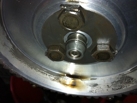
Interestingly, there is no wear to the wooden block below, and additionally there is no cross drilling to increase the oil supply to the camshaft timing gears this version, whereas there was in later engines I built. One of the reasons for examining this, was the owner said the camshaft gear was noisier than he remembered previously, and although the aluminium gear is when compared against the OEM fibre wheel, I’d thought I’d investigate further.

Picture above shows the oil light insulator button from inside the camshaft timing gear case, which acts an insulator and breaks the brass contact for the dash mounted low oil pressure warning light earth loop, but only as the oil pressure in the hollow camshaft gallery builds up.
It’s more remarkable, because this particular engine had very little additional lubrication, other than a little splash bleed from nearby oil galleries, and was the first one where I altered the crankcase lubrication circuits.
This is great news, as I now don’t need to do the brass nosing mod, as shown below, which I did in 2004.
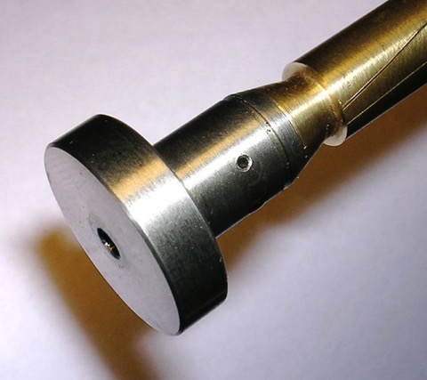
This was done to an earlier engine rebuild for a two bladed fan Dyna engine, because I was concerned about the potential friction that the hollow threaded tip of the piston might create.
This is the later revision to the oil light circuit, and although it’s incomplete, you can see there is a cross drilling that is exposed once the oil pressure builds up in the camshaft gallery. The relief valve can be set, so that the first priority is the crankshaft big end rollers, and the hole size can be varied if more lubrication is needed to these timing gears. However, as this oil feed is off the central oil gallery within the camshaft, there is no pressure fluctuations as the camshaft rotates to either big end bearing, so eliminating all the developmental faults that were introduced as the years went by.
so I created this replacement in mild steel. This is the basic part, because I hand finish this further.
This is used with other mods to refine the Panhard oil lubrication circuits. The nose was rounded in the picture below to prevent wearing out the wooden plug that pushes the oil light contact, once the engine gets up to pressure.
I happened to be stripping an engine to use in my EFI project, and I came across this, which was an earlier prototype 1990’s part that I fitted to an engine in 2002, and because I was relying on splash and bleeding from the oil ways nearby, it didn’t need the cross drilling.
Interestingly, there is no wear to the wooden block below, and additionally there is no cross drilling to increase the oil supply to the camshaft timing gears this version, whereas there was in later engines I built. One of the reasons for examining this, was the owner said the camshaft gear was noisier than he remembered previously, and although the aluminium gear is when compared against the OEM fibre wheel, I’d thought I’d investigate further.
Picture above shows the oil light insulator button from inside the camshaft timing gear case, which acts an insulator and breaks the brass contact for the dash mounted low oil pressure warning light earth loop, but only as the oil pressure in the hollow camshaft gallery builds up.
It’s more remarkable, because this particular engine had very little additional lubrication, other than a little splash bleed from nearby oil galleries, and was the first one where I altered the crankcase lubrication circuits.
This is great news, as I now don’t need to do the brass nosing mod, as shown below, which I did in 2004.
This was done to an earlier engine rebuild for a two bladed fan Dyna engine, because I was concerned about the potential friction that the hollow threaded tip of the piston might create.
This is the later revision to the oil light circuit, and although it’s incomplete, you can see there is a cross drilling that is exposed once the oil pressure builds up in the camshaft gallery. The relief valve can be set, so that the first priority is the crankshaft big end rollers, and the hole size can be varied if more lubrication is needed to these timing gears. However, as this oil feed is off the central oil gallery within the camshaft, there is no pressure fluctuations as the camshaft rotates to either big end bearing, so eliminating all the developmental faults that were introduced as the years went by.
Panhard oil light piston developments
Friday 02 April 2004
As part of my lubrication works I made some oil light pistons to replace the standard machined cast originals shown in the bottom picture.
The original had a rounded tip, whereas mine had a threaded hole, which was part of the oil relief valve assembly, and I couldn’t really alter this unless I made a two part piston.
There was a concern that this nosing or tip, despite being rounded similar to the picture below …
… would still abrade the oil light wooden button, and cause problems further down the line. To negate this I started work on a one off two part oil light piston assembly.
First I had to replace the set screw and create a guide for the relief valve spring. I made this part in brass using the lathe from a piece I had lying around that I was going to use to replace a missing foot off my favourite briefcase!
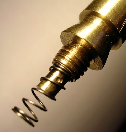
Then cut down a replacement oil light piston, and put them together, to look like this.
This was the finished product within the camshaft gear...
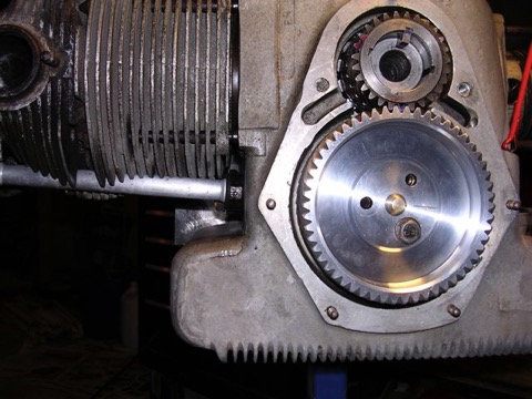
…and here is a close up.
UPDATE (2011) Link to this post
It turns out this wasn’t necessary, as upon examining another early engine, with this rounded oil light piston tip fitted there was no wear to the wooden block, so this work wasn’t required, but at least there is another option for those that don’t believe me.
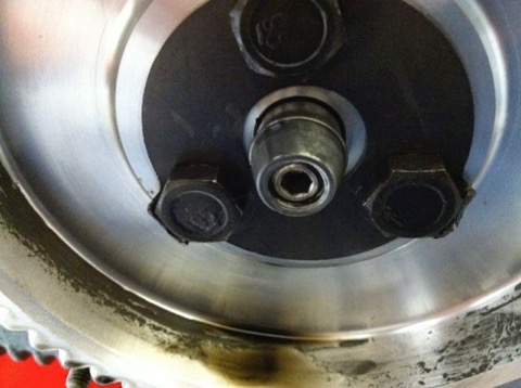
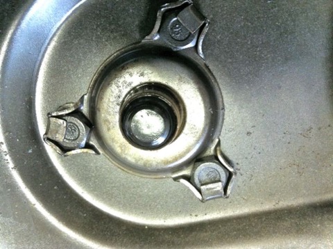
The original had a rounded tip, whereas mine had a threaded hole, which was part of the oil relief valve assembly, and I couldn’t really alter this unless I made a two part piston.
There was a concern that this nosing or tip, despite being rounded similar to the picture below …
… would still abrade the oil light wooden button, and cause problems further down the line. To negate this I started work on a one off two part oil light piston assembly.
First I had to replace the set screw and create a guide for the relief valve spring. I made this part in brass using the lathe from a piece I had lying around that I was going to use to replace a missing foot off my favourite briefcase!
Then cut down a replacement oil light piston, and put them together, to look like this.
This was the finished product within the camshaft gear...
…and here is a close up.
UPDATE (2011) Link to this post
It turns out this wasn’t necessary, as upon examining another early engine, with this rounded oil light piston tip fitted there was no wear to the wooden block, so this work wasn’t required, but at least there is another option for those that don’t believe me.
Panhard double sump double pump oil filter
Wednesday 03 March 2004
The existing Panhard oil filter mod I created works well at lowering the oil temperature, but there was a nagging doubt that all was not as good as it could be, because on a longer run the temperature would climb, but drop when the revs were dropped. It looked like an under capacity issue, and although you can add oil coolers, the Panhard race cars went to a double sump arrangement. This was an additional sump casting that attached to the existing and was held in place by longer studs.
To test this out, I would need to make a mod to my existing Panhard oil filter to accept a double pump, because just making a longer inlet an adding an external filter, would reduce the ground clearance, and possibly cause another issue when the filter got hit. In reality, a PL17 would be OK, but I decided to look at this further, especially when Ron Tyrrell offered a double sump casting and double pump for me to work with.
Eventually I used a variation of this internal filter, and a shortened oil pick up from the standard external oil filter kit, and made a new sump plate on the lathe. The slight bump in the middle was to centre the internal oil filter, when you attached the sump plate to the double sump.

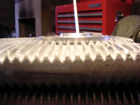
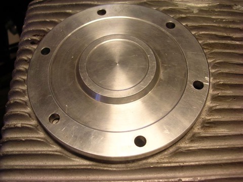
The sump plate was substantially thinner, but the oil changing was going to be messy, because there was no drain plug fitted.
In conclusion, the new filter arrangement worked very well in Ron’s car, and oil temperatures were consistently lower at speed, and did not climb into the higher levels he had seen previously in motorway work. He is convinced the increase in capacity is the correct way to go, because if it was a flow rate issue, the oil temperatures would stay high. Unfortunately, double sump castings are rarely available, but anything you do to increase the oil capacity of these engines will be beneficial.
To test this out, I would need to make a mod to my existing Panhard oil filter to accept a double pump, because just making a longer inlet an adding an external filter, would reduce the ground clearance, and possibly cause another issue when the filter got hit. In reality, a PL17 would be OK, but I decided to look at this further, especially when Ron Tyrrell offered a double sump casting and double pump for me to work with.
Eventually I used a variation of this internal filter, and a shortened oil pick up from the standard external oil filter kit, and made a new sump plate on the lathe. The slight bump in the middle was to centre the internal oil filter, when you attached the sump plate to the double sump.
The sump plate was substantially thinner, but the oil changing was going to be messy, because there was no drain plug fitted.
In conclusion, the new filter arrangement worked very well in Ron’s car, and oil temperatures were consistently lower at speed, and did not climb into the higher levels he had seen previously in motorway work. He is convinced the increase in capacity is the correct way to go, because if it was a flow rate issue, the oil temperatures would stay high. Unfortunately, double sump castings are rarely available, but anything you do to increase the oil capacity of these engines will be beneficial.
Panhard internal filter vs external filter modifications
Sunday 22 February 2004
I found these pictures in my iPhoto gallery, so I’d thought I’d update the records. These pictures are from the prototype internal filter versions I made.
Standard filter arrangement with camera shake, showing standard crankcase sump below. The later cylindrical gauze screen is shown below, with the earlier tapered type underneath this.
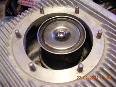
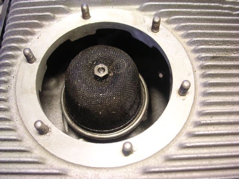
This is my external oil filter conversion pictured below, but in order to reduce the ground clearance, it was decided to try and put the oil filter inside, which obviously makes oil changing potential awkward.
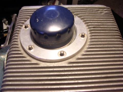
This is first attempt, which used an internal filter I had lying around, and it wasn’t really suitable, as the clearance would have been no better.
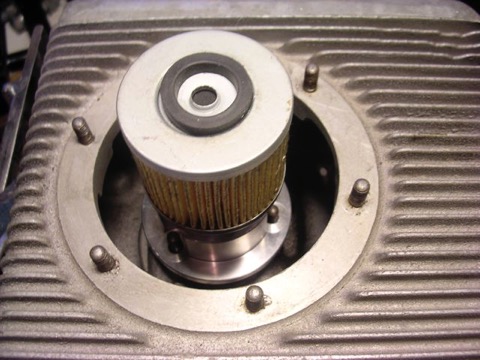
To make this fit, I had to revise the inlet pick up pipe, and I wasn’t that happy about the one way valve in the base of the filter either, or the depth of the raw aluminium billet to create a sump plate. This is the raw baseplate being checked for size. For economic reasons I didn’t want to deviate from my replacement oil filter kit too much, so I was always looking to minimise the changes needed.
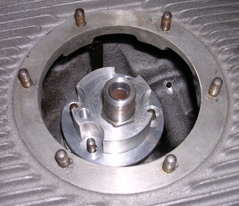
I managed to find a shallower filter, shown below and this fitted into the standard sump casting, but I haven’t machined the pick up pipe yet...
…and here is the complete assembly, essentially the revised internal filter set up, showing the new sump plate.
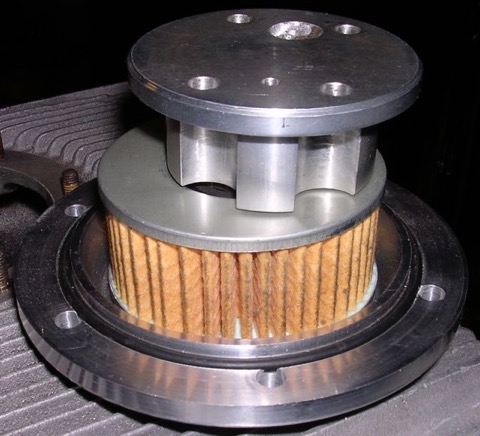
However, another session on the lathe produced this, and I just needed to find a drain plug...
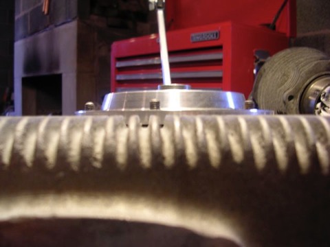
…which I did here, and the sump plate is substantially lower than the first version, but more practical and not as tall a fitting as my standard replacement filter cartridge, shown below (the blue one)
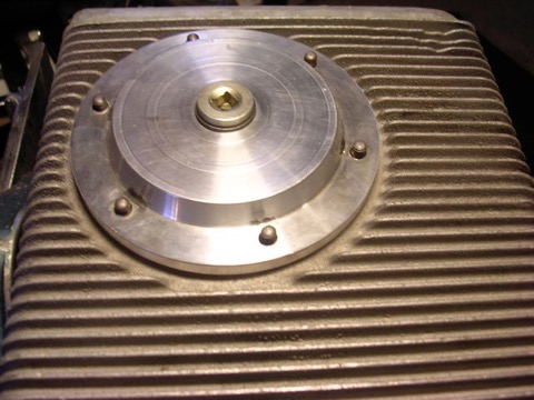

Standard filter arrangement with camera shake, showing standard crankcase sump below. The later cylindrical gauze screen is shown below, with the earlier tapered type underneath this.
This is my external oil filter conversion pictured below, but in order to reduce the ground clearance, it was decided to try and put the oil filter inside, which obviously makes oil changing potential awkward.
This is first attempt, which used an internal filter I had lying around, and it wasn’t really suitable, as the clearance would have been no better.
To make this fit, I had to revise the inlet pick up pipe, and I wasn’t that happy about the one way valve in the base of the filter either, or the depth of the raw aluminium billet to create a sump plate. This is the raw baseplate being checked for size. For economic reasons I didn’t want to deviate from my replacement oil filter kit too much, so I was always looking to minimise the changes needed.
I managed to find a shallower filter, shown below and this fitted into the standard sump casting, but I haven’t machined the pick up pipe yet...
…and here is the complete assembly, essentially the revised internal filter set up, showing the new sump plate.
However, another session on the lathe produced this, and I just needed to find a drain plug...
…which I did here, and the sump plate is substantially lower than the first version, but more practical and not as tall a fitting as my standard replacement filter cartridge, shown below (the blue one)
Panhard revised lubrication circuits
Sunday 02 June 2002
I have updated the content to reflect my latest work, and put all the oil circuit mods in one place.
A quick history lesson on Panhard engine failures. The front main bearing and front cylinder crankshaft big end started to develop failures, as they increased the horsepower. It was attributed to insufficient oil supply, and so the front end lubrication was revised, and the camshaft timing gears were used as a splash lubrication system and the oil drilling that provided that role under the front main bearing was removed. This modification was introduced from around the early 1960’s, and ran to the end of production in 1967.
Unfortunately for Panhard they were barking up the wrong tree, despite the engine coming from a well thought out design originally, other people tinkered with the design knee jerk fashion as the problems developed, and nobody took an overview and look at the root causes. The financial woes and Citröen management probably didn’t help, but as Panhard died in 1967, we will never really know.
Flash forward to the next century, and if you are running one of these engines, it will almost be suffering from the result of this modification. As the engine ages the oil pump becomes more marginal, the priority oil fed valve gear bushes in the head wear, and the oil into the camshaft gallery reduces. Now the front bearings don’t really fatigue like they used to, but the rears suffer because they are pump related. So the problem has transferred itself, and the question that should be asked is why?
Of course if you look at the development of these engines you will read about the engines modified for endurance racing, which had higher capacity pumps, and an increased oil capacity with the fitment of an additional sump, that also acted as a baffled cavity for the oil pick up pipe. This subset of development has been an evolutionary branch of Panhard engine that needs revising, because if you really look at the problem, these solutions are papering over the cracks of a design fault. If you go back in time, and look at the engine design of the Panhard flat twin compared to others, there are numerous good points taken from lots of influences. The crankshaft oil supply is reminiscent of Bugatti & the early BMW motorcycle engines, but it is essentially a low pressure system, and even the design of the original plain bearing surfaces reflect this, so why fit a higher pressure set up, but that’s another story.
For example in the front bearing of the camshaft, which has a very large diameter at the front where the timing gear is driven by the crankshaft, and a more normal sized bearing diameter at the rear. Also, if you look at the oil drillings that feed these plain bearings, they are proportionately scaled to suit. The camshaft is the common denominator in all of this because it is one of three main oil feeds from the oil pump, and the supply conduit for the front and rear main bearings and the crankshaft lubrication, but wasn’t there a problem here?
So how can a central oil gallery that feeds both the front and rear crankshafts be at fault? Actually, the central gallery is not the problem, because the flow into this is separate from the outputs, and if you look at these, the problem is almost explained. The original designer knew he needed to equalise the distribution of the oil, so the oil outputs for the front and rear crankshaft feeds are phased to do just this, and as the cross drillings are on a rotating surface the timing window on the camshafts are scaled accordingly. However, although the rear crankshaft oil drilling is sized to match the rear camshaft drilling, the front is mismatched, because the oil drilling in the crankcase is too small.
On examination the oil drilling needs to be around 6mm diameter, when it is only 4mm, which is a 50% reduction in oil supply compared to the rear, and this alone would explain the front end failure susceptibility, but it doesn’t end there. The original designer tried to phase the oil supply to the front and rear ends equally, but somebody else decided the camshaft timing gear at the front should have some more lubrication, and put in an additional drilling. The reality was that the original plain bearing would have leaked into this cavity, and as there were no low level drainage holes, the oil wouldn’t go away, so it really didn’t need the additional drilling, but the biggest problem was where it was positioned. The oil pump doesn’t need to be big, as the engine only needed low flow rates and low pressure to work within it original design specifications, however any pressure drop say after a drilling would take a little time to recover, and this was accepted in the design layout, but as soon as the oil drilling to the front timing gear was placed ahead of the front end oil supply, the 50% reduction in flow rate all things being equal just got worse, as this drilling lost pressure after 60 degrees of a 90 degree recovery window, and only gave the camshaft 30 degrees to recover the oil pressure in the gallery. This means the front crankshaft oil feeds are compromised further, whereas the rears are unaffected, and it was all down to a simple production oversight.
What is the solution? Again, a quick history lesson will tell you all you need to know, and it is the route of many flat twin Panhard devotees, but don’t bother looking at the history books, what you have to do is engine specific, but that’ll be for another day. Suffice to say, I spotted this many years ago, and have been making parts and modding a few engines to overcome these oil related faults every time I get hold of one.
This is the cleaned crankcase marked up and ready for the knife or Foredom.
I have to modify the later style crankcase to adjust the oil circulation. This will mean creating a new big end feed under the front main bearing, plugging some of the existing galleries, and making new drain holes for the front timing gear. This will reduce pumping losses, lower oil temperatures and improve oil quality. After this I will be refining the existing oil galleries to reduce back pressure and cavitation, so increasing the nett flow rate of the existing oil pump.
Contrary to what others are saying or you might have heard elsewhere, this oil pump is more than capable of feeding the demands of the standard Panhard engine, and these mods to the front end boost pressure to the plain bearing surfaces, especially when combined with my camshaft oil light piston, so it’s a win win situation, but if I was going to spend money on something extra to improve things further, I would boost the oil capacity by increasing the sump volume.
Panhard oil filter, article from Panoramique
Sunday 12 April 1998
The start of the Panhard oil filter story...I owned a Panhard 17BT RelmaxS in 1984, only used it for 850 miles before it expired with a holed piston, but what a great feeling it was while it lasted. Read More...
