Panhard crankcase oil circulation modifications (revisited)
Saturday 03 March 2012 Filed in: Panhard Oil
A quick history lesson on Panhard engine failures. The front main bearing and front cylinder crankshaft big end started to develop failures, as they increased the horsepower. It was attributed to insufficient oil supply, and so the front end lubrication was revised, and the camshaft timing gears were used as a splash lubrication system and the oil drilling that provided that role under the front main bearing was removed. This modification was introduced from around the early 1960’s, and ran to the end of production in 1967.
Unfortunately for Panhard they were barking up the wrong tree, despite the engine coming from a well thought out design originally, other people tinkered with the design knee jerk fashion as the problems developed, and nobody took an overview and look at the root causes. The financial woes and Citröen management probably didn’t help, but as Panhard died in 1967, we will never really know.
Flash forward to the next century, and if you are running one of these engines, it will almost be suffering from the result of this modification. As the engine ages the oil pump becomes more marginal, the priority oil fed valve gear bushes in the head wear, and the oil into the camshaft gallery reduces. Now the front bearings don’t really fatigue like they used to, but the rears suffer because they are pump related. So the problem has transferred itself, and the question that should be asked is why?
Of course if you look at the development of these engines you will read about the engines modified for endurance racing, which had higher capacity pumps, and an increased oil capacity with the fitment of an additional sump, that also acted as a baffled cavity for the oil pick up pipe. This subset of development has been an evolutionary branch of Panhard engine that needs revising, because if you really look at the problem, these solutions are papering over the cracks of a design fault. If you go back in time, and look at the engine design of the Panhard flat twin compared to others, there are numerous good points taken from lots of influences. The crankshaft oil supply is reminiscent of Bugatti & the early BMW motorcycle engines, but it is essentially a low pressure system, and even the design of the original plain bearing surfaces reflect this, so why fit a higher pressure set up, but that’s another story.
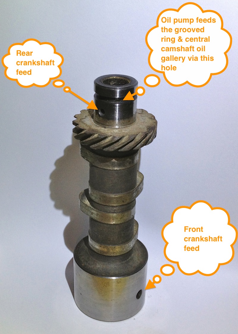
For example in the front bearing of the camshaft, which has a very large diameter at the front where the timing gear is driven by the crankshaft, and a more normal sized bearing diameter at the rear. Also, if you look at the oil drillings that feed these plain bearings, they are proportionately scaled to suit. The camshaft is the common denominator in all of this because it is one of three main oil feeds from the oil pump, and the supply conduit for the front and rear main bearings and the crankshaft lubrication, but wasn’t there a problem here?
So how can a central oil gallery that feeds both the front and rear crankshafts be at fault? Actually, the central gallery is not the problem, because the flow into this is separate from the outputs, and if you look at these, the problem is almost explained. The original designer knew he needed to equalise the distribution of the oil, so the oil outputs for the front and rear crankshaft feeds are phased to do just this, and as the cross drillings are on a rotating surface the timing window on the camshafts are scaled accordingly. However, although the rear crankshaft oil drilling is sized to match the rear camshaft drilling, the front is mismatched, because the oil drilling in the crankcase is too small.
On examination the oil drilling needs to be around 6mm diameter, when it is only 4mm, which is a 50% reduction in oil supply compared to the rear, and this alone would explain the front end failure susceptibility, but it doesn’t end there. The original designer tried to phase the oil supply to the front and rear ends equally, but somebody else decided the camshaft timing gear at the front should have some more lubrication, and put in an additional drilling. The reality was that the original plain bearing would have leaked into this cavity, and as there were no low level drainage holes, the oil wouldn’t go away, so it really didn’t need the additional drilling, but the biggest problem was where it was positioned. The oil pump doesn’t need to be big, as the engine only needed low flow rates and low pressure to work within it original design specifications, however any pressure drop say after a drilling would take a little time to recover, and this was accepted in the design layout, but as soon as the oil drilling to the front timing gear was placed ahead of the front end oil supply, the 50% reduction in flow rate all things being equal just got worse, as this drilling lost pressure after 60 degrees of a 90 degree recovery window, and only gave the camshaft 30 degrees to recover the oil pressure in the gallery. This means the front crankshaft oil feeds are compromised further, whereas the rears are unaffected, and it was all down to a simple production oversight.
What is the solution? Again, a quick history lesson will tell you all you need to know, and it is the route of many flat twin Panhard devotees, but don’t bother looking at the history books, what you have to do is engine specific, but that’ll be for another day. Suffice to say, I spotted this many years ago, and have been making parts and modding a few engines to overcome these oil related faults every time I get hold of one.
A quick walkthrough of what to do
1. Mod the oil pump
2. Mod the crankcase oil circuits, two different methods for the M6 & M10 engines.
3. Make a new oil light piston or buy one from me
1. Modify the oil pump
Originally the engine had a lot of roller bearings inside it, and crucially the crankshaft was suspended using these. In fact cylindrical roller bearing set ups are making a come back in engine design, especially in the USA where Timken are applying this to some current engines, to showcase the technology again, and also promote their own bearing interests. One of the reasons they are using it, is to reduce pumping losses, and the frictional drag reductions against the more common plain bearing engines, because there is an environmental need to make combustion engines more economical.
The Panhard engine was quite clever in that it used a small pump to get the oil roughly where it was needed, and then the centrifugal effect of the slingers in the crankshaft webs gave a speed related response to the engine needs. This was a good fit with the requirements of the engine, and although there was a maintenance issue with slingers clogging up, mileages were not great in the late 1940’s when the engine was being designed, and a 30,000 mile target wasn’t unreasonable. Fast forward to the 21st Century and maybe some things would be different now, and if you look at the evolution of a similar engine, the BMW R50 motorcycle, that moved from centrifugal oil supply to a cross drilled crank, and the more common one piece crankshaft & split connecting rods with plain bearings.
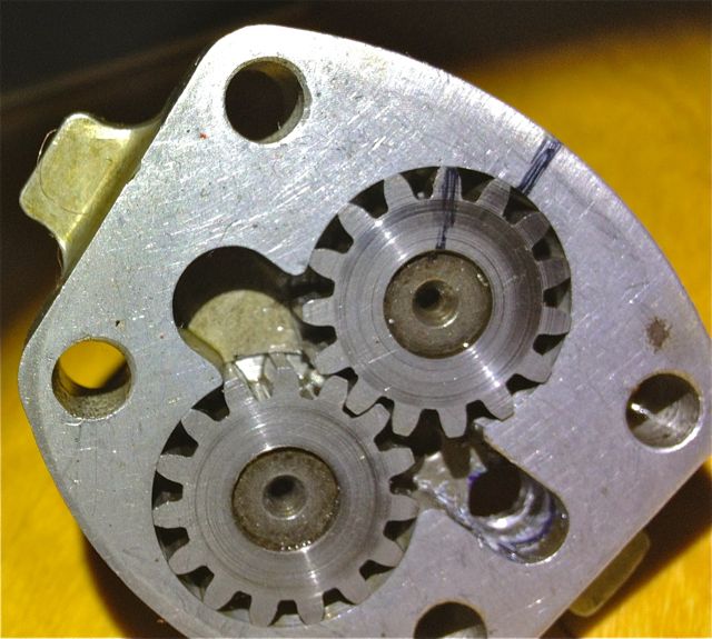
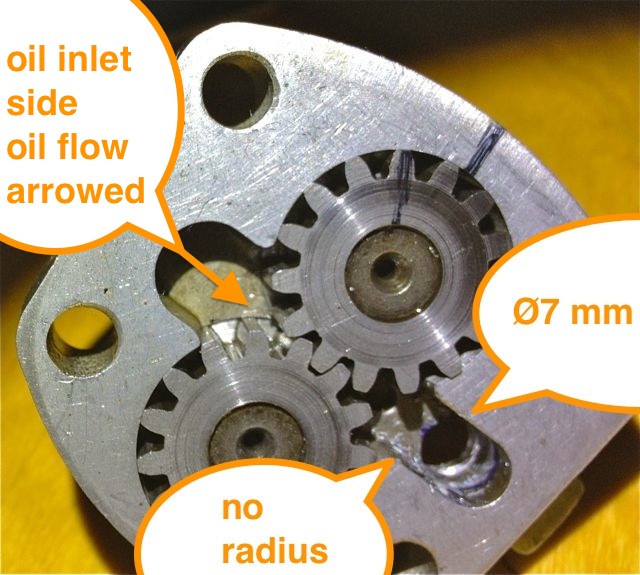
Aside from the maintenance issue with the slingers, there is nothing really wrong with the original oil pump, but if you read the history books you might be lead to believe otherwise. Here is the pump, and it is a gear type oil pump, which was a current design around the time, and it is more than adequate for the job. There are a couple of issues, that if it was being made today, that you would change, but I’ll elaborate later.The first one is, there are no rounded edges from the oil pump body into the output drilling, which is 90 degrees to it, and this will cause back pressure and cavitation, at higher oil volumes .
So if I was going to do one thing to address this, it would involve using a Dremel and doing this.
This modified oil pump will now flow more oil at speed, when you want it and there will be less bubbles in the oil as a result, which has the effect of improving the oil quality. I have successfully done this on three engines to date, and did test it out on the oil filter crankcase test rig many years ago. It is beneficial, and is one way of simply boosting the nett oil flow, but there is a bigger win win at the crankcase entry. If you were trying to maximise flow, you wouldn’t squeeze a garden hose pipe, but that’s exactly what Panhard did, because the crankcase oil inlet from the pump is 4.8mm diameter, yet the pump output is 7mm in diameter, which is almost a 50% reduction in cross sectional area. So after radiussing the outlet of the pump body there is an even bigger restriction downstream, and all the oil for the engine is fed by this small hole. It really doesn’t make sense with hindsight
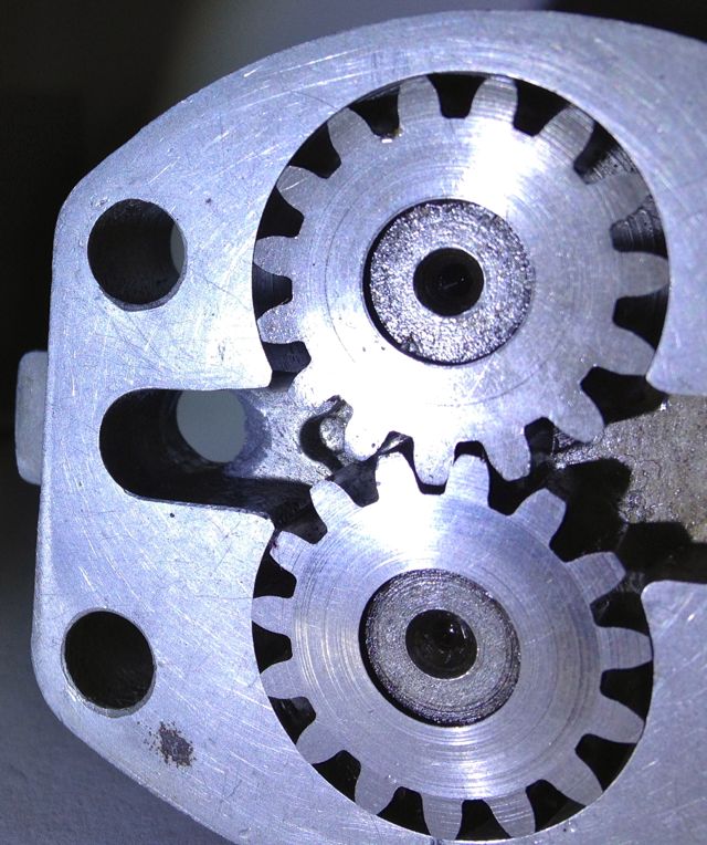
You can see the small inlet pipe into the crankcase, and also see where the oil pump mates up to it, which is the black circle I have inked in and the centre of the outlet is represented by the black lines. So again the flexible shaft is used to reshape this area, and the important thing is to match the mating diameters more closely. It makes sense to machine and open up this drilling to match the oil pump, as this will increase the flow rate into the main oil galleries, and it has no effect on the pressure of the system, contrary to what you might think. The pressure in the unmodified camshaft is controlled by the cross drilling after this, and the cylinder head feeds likewise by the size of their respective openings too.
Crankcase main oil gallery modified to match oil pump outlet diameter.
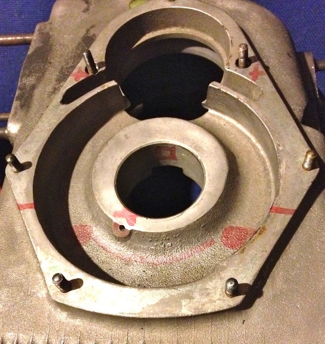
2. Modify the crankcase (M10S version below)
This engine is the later type, so needs modifying back to the original oil supply route, but adding the improvements necessary to negate the other faults. The first area to tackle is the front end crankshaft oil supply, so plugging the newer oil drillings and creating a matched new one under the front main bearing housing. These will be fixed with Loctite once all the drilling has finished and the crankcase has been thoroughly cleaned.
I will reduce the oil level & flow in the timing gear casing, so reduce pumping losses, and oil degradation. On examination the deposits in the slingers at the front part of the crankshaft were almost double those at the rear, which is mainly due to the oil supply being much greater to the front and also the timing gear casing is a stale oil residue trap. Once contaminated here, the particulates have no option but return via the main bearing aperture, and then be centrifuged in the front slinger and as there is no drain out of this area, the oil is never fully refreshed.
I have to modify the later style crankcase to adjust the oil circulation. This will mean creating a new big end feed under the front main bearing, plugging some of the existing galleries, and making new drain holes for the front timing gear. This will reduce pumping losses, lower oil temperatures and improve oil quality.
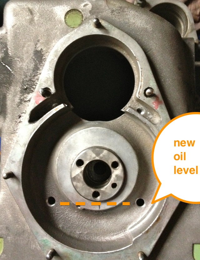
At the moment the Panhard timing case oil level is determined by the high level drainage points shown here or leaking past the front main bearing. In reality the OEM oil level never reaches this height, because the gears act like a huge waterwheel and churn through the bearing, but this still causes parasitic losses, and the modded race cars aka DBs, used a modified timing gear to overcome this.
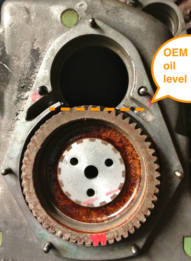
Normal practice for a splash lubricated gear is to have no more than a third of the overall gear diameter immersed, so why Panhard did this surprises me. Originally they had a fibre wheel of massive proportions meshing to a hardened steel gear, with huge gear area, and in all fairness it probably didn’t need much lubrication. If it was being made today this fibre wheel, which is often replaced by an aluminium one, could be made of a plastic material quite easily.
These new drillings, now restore the status quo, and at the same time allow for this area to get some oil changes. Technically these wouldn’t get fully drained, unless you remove the steel timing cover case, because there is no low level return point. I think it is realistic to revise this mod and lower the oil level further, but as this is the third engine I have modded in this area, I will wait until I get some better feedback before doing so.
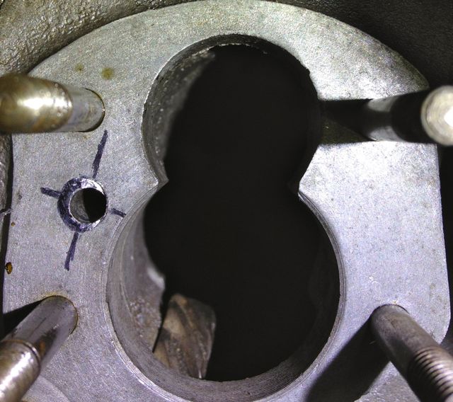
Now to mod the front crankshaft oil feed.
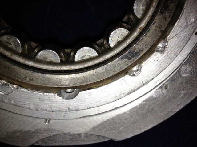
The later engines didn’t have this option, as can be seen here.

The original engines had this oil feed visible above the camshaft bore at the very front of the crankcase, which is shown below. As the camshaft rotates this drilling is filled two times per camshaft revolution, and after this it passes in a trough that is underneath the bearing and the oil jumps into the slingers. Some oil splashes back and passes through the main bearing, but the rest is accelerated by the slingers at the crank web, and passes through the big end bearing via a drilling in the crank web before exiting and splash lubricating the little end.
Unfortunately this hole is too small, and it is the cause of a 50% reduction in flow rate over the rear pro rata. There is an added complication that this hole is also 50% smaller than the rear oil feed, so there is quite a bit of reduction in potential flow rate assuming the pressures were the same. As you might have read there is a pressure difference, because of the secondary drilling that fed the camshaft timing gear on the early engines which compounded the problem , and led to reliability issues, which eventually forced an engine redesign to this area.
This can be negated by carrying out a few modifications, all of which will be documented here.
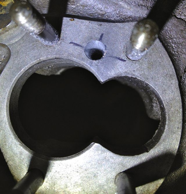
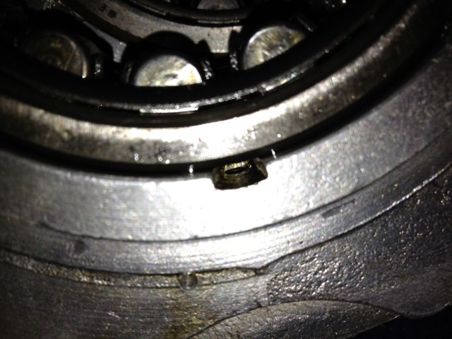
It might not be obviously apparent from this picture, but the hole size is now 6mm diameter, whereas the one above is just 4mm. This new oil feed now matches the camshaft aperture, so all openings, front and rear are timed equally. The 4mm diameter hole in the middle that is drilled presently, will have to be enlarged to 5mm to match the rear oil feed that is fed from the common camshaft oil gallery. At first it is more important to get the hole in the right position, and work from this, which is why it is now at 5mm diameter, as shown below.
Timing gear oil drilling plugged as shown below
Plugging this drilling means both front and rear oil galleries are now equally phased and have the same pressure variations, as there is no mismatched timing gear oil feed anymore affecting the front oil supply. However that still leaves the task of creating a new oil feed to do this, because you didn’t think the gear was going to lubricate itself from the plain bearing leaking.
3. Make a new oil light piston or buy one from me!
To lubricate the camshaft gear I made some oil light pistons to replace the standard machined cast originals shown in the bottom picture.
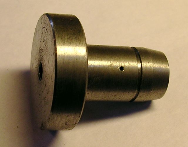
This is the raw machined unit, it still needs a little more work. This new oil light piston has an integral relief valve built in, essentially, a ball spring and locking screw, and I set it at 2 bar or 30psi, but you can set this to whatever you want, and even increase the oil drilling if you want to make it larger.
The importance of this is that the original oil supply will now feed the cylinder heads and the hydraulic valve adjusters first as normal, then the front and rear bearings, and only then squirt oil into the timing gear when more pressure is reached. It also means that after the oil has fed the cylinder heads, the front and rear bearings get a much better oil supply.
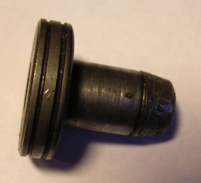
The original had a rounded tip, whereas mine had a threaded hole, which was part of the oil relief valve assembly, and I couldn’t really alter this unless I made a two part piston.
There was a concern that this nosing or tip, despite being rounded similar to the picture below …
… would still abrade the oil light wooden button, and cause problems further down the line. In real usage it has no impact, but I did make a modified version for engine number 3 some years ago, which I believe isn’t necessary now.
So we have almost finished, just need to tweak the rear bearing oil supply...
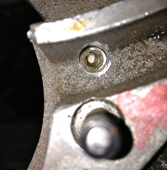
Historically the engines have had gradual tweaks over their lifetime, and the rear main bearing support plate which bolts to the crankcase is no exception. The first ones were aluminium, and the later ones were cast iron with a flexible lipped seal, as opposed to a steel piston ring. Oil starvation and inadequate capacity have always been an issue, as the cars were introduced to the ever increasing demands of modern day traffic, and I spotted another tweak today.
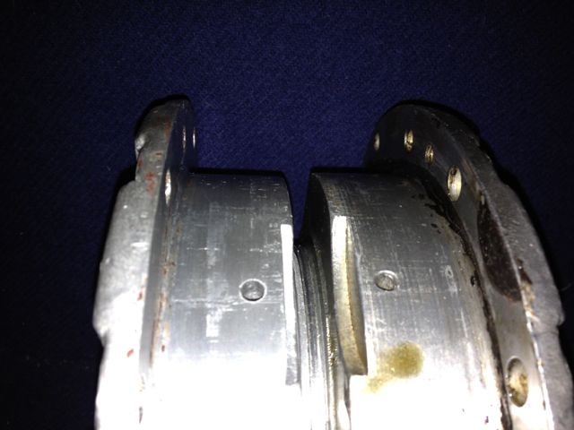
The early M6 back plate is on the left and the later M8 is on the right, and can you spot the difference?
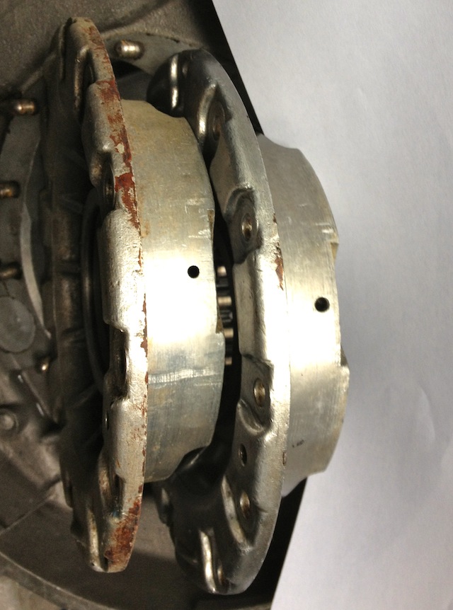
The answer is the holes are bigger on the later one, which means more oil can be supplied to the rear bearing. After measuring these it equates to an improvement of 15% over the earlier design.
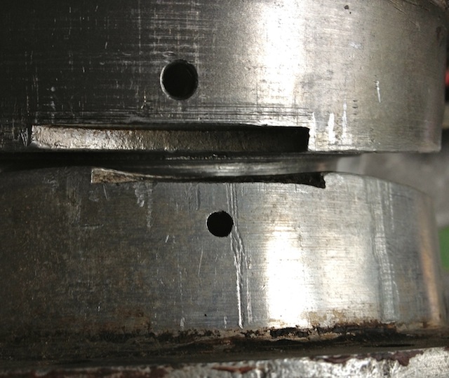
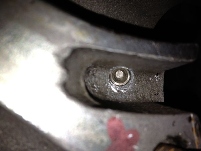
This hole needs to be bigger to reduce the cavitation and back pressure, and also equalise the flow with the improved front bearing oil supply.

This is the left hand M6 casting after being modded at the inlet side, and the outlet must be modded too. Again the change of direction gets a smoothing radius on the inside corner.
.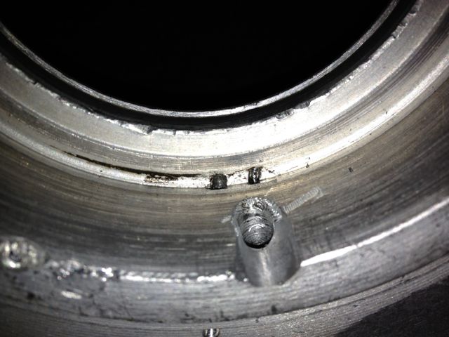
The hole has been smoothed and with a dummy bearing fitted you can see the difference in surface area, versus the older design underneath. What is not apparent is the hole is only 3mm in diameter just under the bearing on this M6 casting.
So that’s it. They are a few other tweaks that can be made, but modifying the oil circuits this way will improve a standard Panhard engine, and increase its reliability, especially if you dilter the oil and increase the sump capacity.
Unfortunately for Panhard they were barking up the wrong tree, despite the engine coming from a well thought out design originally, other people tinkered with the design knee jerk fashion as the problems developed, and nobody took an overview and look at the root causes. The financial woes and Citröen management probably didn’t help, but as Panhard died in 1967, we will never really know.
Flash forward to the next century, and if you are running one of these engines, it will almost be suffering from the result of this modification. As the engine ages the oil pump becomes more marginal, the priority oil fed valve gear bushes in the head wear, and the oil into the camshaft gallery reduces. Now the front bearings don’t really fatigue like they used to, but the rears suffer because they are pump related. So the problem has transferred itself, and the question that should be asked is why?
Of course if you look at the development of these engines you will read about the engines modified for endurance racing, which had higher capacity pumps, and an increased oil capacity with the fitment of an additional sump, that also acted as a baffled cavity for the oil pick up pipe. This subset of development has been an evolutionary branch of Panhard engine that needs revising, because if you really look at the problem, these solutions are papering over the cracks of a design fault. If you go back in time, and look at the engine design of the Panhard flat twin compared to others, there are numerous good points taken from lots of influences. The crankshaft oil supply is reminiscent of Bugatti & the early BMW motorcycle engines, but it is essentially a low pressure system, and even the design of the original plain bearing surfaces reflect this, so why fit a higher pressure set up, but that’s another story.
For example in the front bearing of the camshaft, which has a very large diameter at the front where the timing gear is driven by the crankshaft, and a more normal sized bearing diameter at the rear. Also, if you look at the oil drillings that feed these plain bearings, they are proportionately scaled to suit. The camshaft is the common denominator in all of this because it is one of three main oil feeds from the oil pump, and the supply conduit for the front and rear main bearings and the crankshaft lubrication, but wasn’t there a problem here?
So how can a central oil gallery that feeds both the front and rear crankshafts be at fault? Actually, the central gallery is not the problem, because the flow into this is separate from the outputs, and if you look at these, the problem is almost explained. The original designer knew he needed to equalise the distribution of the oil, so the oil outputs for the front and rear crankshaft feeds are phased to do just this, and as the cross drillings are on a rotating surface the timing window on the camshafts are scaled accordingly. However, although the rear crankshaft oil drilling is sized to match the rear camshaft drilling, the front is mismatched, because the oil drilling in the crankcase is too small.
On examination the oil drilling needs to be around 6mm diameter, when it is only 4mm, which is a 50% reduction in oil supply compared to the rear, and this alone would explain the front end failure susceptibility, but it doesn’t end there. The original designer tried to phase the oil supply to the front and rear ends equally, but somebody else decided the camshaft timing gear at the front should have some more lubrication, and put in an additional drilling. The reality was that the original plain bearing would have leaked into this cavity, and as there were no low level drainage holes, the oil wouldn’t go away, so it really didn’t need the additional drilling, but the biggest problem was where it was positioned. The oil pump doesn’t need to be big, as the engine only needed low flow rates and low pressure to work within it original design specifications, however any pressure drop say after a drilling would take a little time to recover, and this was accepted in the design layout, but as soon as the oil drilling to the front timing gear was placed ahead of the front end oil supply, the 50% reduction in flow rate all things being equal just got worse, as this drilling lost pressure after 60 degrees of a 90 degree recovery window, and only gave the camshaft 30 degrees to recover the oil pressure in the gallery. This means the front crankshaft oil feeds are compromised further, whereas the rears are unaffected, and it was all down to a simple production oversight.
What is the solution? Again, a quick history lesson will tell you all you need to know, and it is the route of many flat twin Panhard devotees, but don’t bother looking at the history books, what you have to do is engine specific, but that’ll be for another day. Suffice to say, I spotted this many years ago, and have been making parts and modding a few engines to overcome these oil related faults every time I get hold of one.
A quick walkthrough of what to do
1. Mod the oil pump
2. Mod the crankcase oil circuits, two different methods for the M6 & M10 engines.
3. Make a new oil light piston or buy one from me
1. Modify the oil pump
Originally the engine had a lot of roller bearings inside it, and crucially the crankshaft was suspended using these. In fact cylindrical roller bearing set ups are making a come back in engine design, especially in the USA where Timken are applying this to some current engines, to showcase the technology again, and also promote their own bearing interests. One of the reasons they are using it, is to reduce pumping losses, and the frictional drag reductions against the more common plain bearing engines, because there is an environmental need to make combustion engines more economical.
The Panhard engine was quite clever in that it used a small pump to get the oil roughly where it was needed, and then the centrifugal effect of the slingers in the crankshaft webs gave a speed related response to the engine needs. This was a good fit with the requirements of the engine, and although there was a maintenance issue with slingers clogging up, mileages were not great in the late 1940’s when the engine was being designed, and a 30,000 mile target wasn’t unreasonable. Fast forward to the 21st Century and maybe some things would be different now, and if you look at the evolution of a similar engine, the BMW R50 motorcycle, that moved from centrifugal oil supply to a cross drilled crank, and the more common one piece crankshaft & split connecting rods with plain bearings.
Aside from the maintenance issue with the slingers, there is nothing really wrong with the original oil pump, but if you read the history books you might be lead to believe otherwise. Here is the pump, and it is a gear type oil pump, which was a current design around the time, and it is more than adequate for the job. There are a couple of issues, that if it was being made today, that you would change, but I’ll elaborate later.The first one is, there are no rounded edges from the oil pump body into the output drilling, which is 90 degrees to it, and this will cause back pressure and cavitation, at higher oil volumes .
So if I was going to do one thing to address this, it would involve using a Dremel and doing this.
This modified oil pump will now flow more oil at speed, when you want it and there will be less bubbles in the oil as a result, which has the effect of improving the oil quality. I have successfully done this on three engines to date, and did test it out on the oil filter crankcase test rig many years ago. It is beneficial, and is one way of simply boosting the nett oil flow, but there is a bigger win win at the crankcase entry. If you were trying to maximise flow, you wouldn’t squeeze a garden hose pipe, but that’s exactly what Panhard did, because the crankcase oil inlet from the pump is 4.8mm diameter, yet the pump output is 7mm in diameter, which is almost a 50% reduction in cross sectional area. So after radiussing the outlet of the pump body there is an even bigger restriction downstream, and all the oil for the engine is fed by this small hole. It really doesn’t make sense with hindsight
You can see the small inlet pipe into the crankcase, and also see where the oil pump mates up to it, which is the black circle I have inked in and the centre of the outlet is represented by the black lines. So again the flexible shaft is used to reshape this area, and the important thing is to match the mating diameters more closely. It makes sense to machine and open up this drilling to match the oil pump, as this will increase the flow rate into the main oil galleries, and it has no effect on the pressure of the system, contrary to what you might think. The pressure in the unmodified camshaft is controlled by the cross drilling after this, and the cylinder head feeds likewise by the size of their respective openings too.
Crankcase main oil gallery modified to match oil pump outlet diameter.
2. Modify the crankcase (M10S version below)
This engine is the later type, so needs modifying back to the original oil supply route, but adding the improvements necessary to negate the other faults. The first area to tackle is the front end crankshaft oil supply, so plugging the newer oil drillings and creating a matched new one under the front main bearing housing. These will be fixed with Loctite once all the drilling has finished and the crankcase has been thoroughly cleaned.
I will reduce the oil level & flow in the timing gear casing, so reduce pumping losses, and oil degradation. On examination the deposits in the slingers at the front part of the crankshaft were almost double those at the rear, which is mainly due to the oil supply being much greater to the front and also the timing gear casing is a stale oil residue trap. Once contaminated here, the particulates have no option but return via the main bearing aperture, and then be centrifuged in the front slinger and as there is no drain out of this area, the oil is never fully refreshed.
I have to modify the later style crankcase to adjust the oil circulation. This will mean creating a new big end feed under the front main bearing, plugging some of the existing galleries, and making new drain holes for the front timing gear. This will reduce pumping losses, lower oil temperatures and improve oil quality.
At the moment the Panhard timing case oil level is determined by the high level drainage points shown here or leaking past the front main bearing. In reality the OEM oil level never reaches this height, because the gears act like a huge waterwheel and churn through the bearing, but this still causes parasitic losses, and the modded race cars aka DBs, used a modified timing gear to overcome this.
Normal practice for a splash lubricated gear is to have no more than a third of the overall gear diameter immersed, so why Panhard did this surprises me. Originally they had a fibre wheel of massive proportions meshing to a hardened steel gear, with huge gear area, and in all fairness it probably didn’t need much lubrication. If it was being made today this fibre wheel, which is often replaced by an aluminium one, could be made of a plastic material quite easily.
These new drillings, now restore the status quo, and at the same time allow for this area to get some oil changes. Technically these wouldn’t get fully drained, unless you remove the steel timing cover case, because there is no low level return point. I think it is realistic to revise this mod and lower the oil level further, but as this is the third engine I have modded in this area, I will wait until I get some better feedback before doing so.
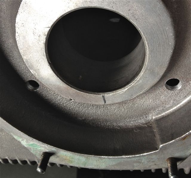
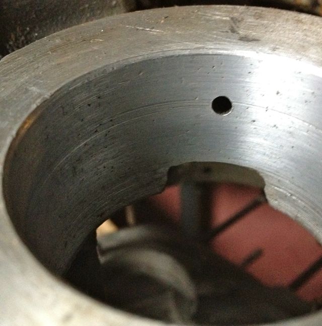
Now to mod the front crankshaft oil feed.
The later engines didn’t have this option, as can be seen here.
The original engines had this oil feed visible above the camshaft bore at the very front of the crankcase, which is shown below. As the camshaft rotates this drilling is filled two times per camshaft revolution, and after this it passes in a trough that is underneath the bearing and the oil jumps into the slingers. Some oil splashes back and passes through the main bearing, but the rest is accelerated by the slingers at the crank web, and passes through the big end bearing via a drilling in the crank web before exiting and splash lubricating the little end.
Unfortunately this hole is too small, and it is the cause of a 50% reduction in flow rate over the rear pro rata. There is an added complication that this hole is also 50% smaller than the rear oil feed, so there is quite a bit of reduction in potential flow rate assuming the pressures were the same. As you might have read there is a pressure difference, because of the secondary drilling that fed the camshaft timing gear on the early engines which compounded the problem , and led to reliability issues, which eventually forced an engine redesign to this area.
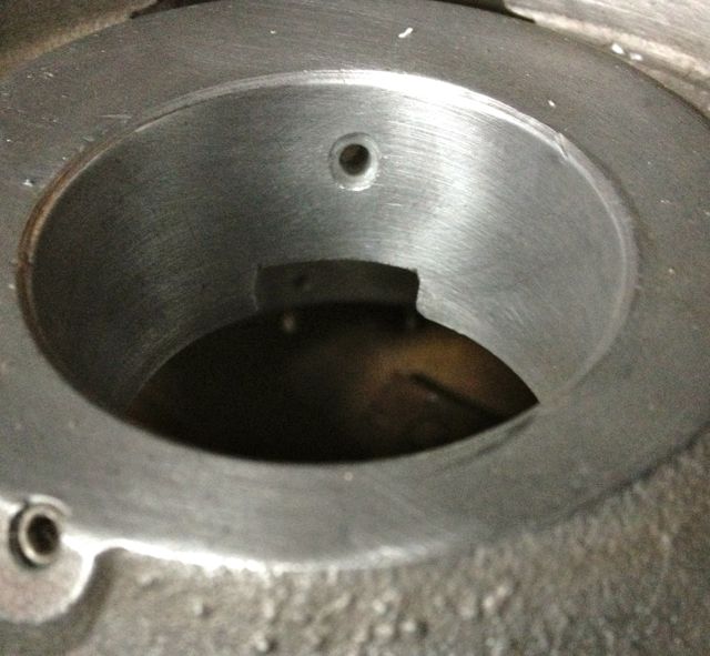
This can be negated by carrying out a few modifications, all of which will be documented here.
It might not be obviously apparent from this picture, but the hole size is now 6mm diameter, whereas the one above is just 4mm. This new oil feed now matches the camshaft aperture, so all openings, front and rear are timed equally. The 4mm diameter hole in the middle that is drilled presently, will have to be enlarged to 5mm to match the rear oil feed that is fed from the common camshaft oil gallery. At first it is more important to get the hole in the right position, and work from this, which is why it is now at 5mm diameter, as shown below.
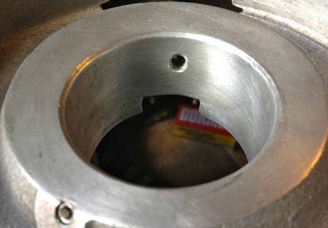
Timing gear oil drilling plugged as shown below
Plugging this drilling means both front and rear oil galleries are now equally phased and have the same pressure variations, as there is no mismatched timing gear oil feed anymore affecting the front oil supply. However that still leaves the task of creating a new oil feed to do this, because you didn’t think the gear was going to lubricate itself from the plain bearing leaking.
3. Make a new oil light piston or buy one from me!
To lubricate the camshaft gear I made some oil light pistons to replace the standard machined cast originals shown in the bottom picture.
This is the raw machined unit, it still needs a little more work. This new oil light piston has an integral relief valve built in, essentially, a ball spring and locking screw, and I set it at 2 bar or 30psi, but you can set this to whatever you want, and even increase the oil drilling if you want to make it larger.
The importance of this is that the original oil supply will now feed the cylinder heads and the hydraulic valve adjusters first as normal, then the front and rear bearings, and only then squirt oil into the timing gear when more pressure is reached. It also means that after the oil has fed the cylinder heads, the front and rear bearings get a much better oil supply.
The original had a rounded tip, whereas mine had a threaded hole, which was part of the oil relief valve assembly, and I couldn’t really alter this unless I made a two part piston.
There was a concern that this nosing or tip, despite being rounded similar to the picture below …
… would still abrade the oil light wooden button, and cause problems further down the line. In real usage it has no impact, but I did make a modified version for engine number 3 some years ago, which I believe isn’t necessary now.
So we have almost finished, just need to tweak the rear bearing oil supply...
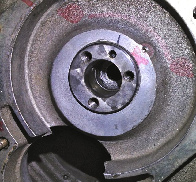
Historically the engines have had gradual tweaks over their lifetime, and the rear main bearing support plate which bolts to the crankcase is no exception. The first ones were aluminium, and the later ones were cast iron with a flexible lipped seal, as opposed to a steel piston ring. Oil starvation and inadequate capacity have always been an issue, as the cars were introduced to the ever increasing demands of modern day traffic, and I spotted another tweak today.
The early M6 back plate is on the left and the later M8 is on the right, and can you spot the difference?
The answer is the holes are bigger on the later one, which means more oil can be supplied to the rear bearing. After measuring these it equates to an improvement of 15% over the earlier design.
This hole needs to be bigger to reduce the cavitation and back pressure, and also equalise the flow with the improved front bearing oil supply.
This is the left hand M6 casting after being modded at the inlet side, and the outlet must be modded too. Again the change of direction gets a smoothing radius on the inside corner.
.
The hole has been smoothed and with a dummy bearing fitted you can see the difference in surface area, versus the older design underneath. What is not apparent is the hole is only 3mm in diameter just under the bearing on this M6 casting.
So that’s it. They are a few other tweaks that can be made, but modifying the oil circuits this way will improve a standard Panhard engine, and increase its reliability, especially if you dilter the oil and increase the sump capacity.
blog comments powered by Disqus
