2016
New crankshaft design
22/04/16 01:21
I am finally updating the website after a long time out, and will be adding info and refining the content over the next few weeks, as I haven't been doing nothing Panhard before an enforced break.
DCNF carburettor modifications
22/04/16 01:20
Investigate the valve gear return spring tension
22/04/16 01:20
Crankshaft failure
08/02/16 01:21
A most disappointing start to the day, as I had a friend come round to the house, and he asked how the engine was going, so I said, "Have a look for yourself".
We nipped into the shed, and I started it, and he was gobsmacked it sound so quiet on open pipes, and after I released the choke, I left the engine on a slow idle to warm up. After a cup of tea, we went back to the shed, and I checked the exhausts and cylinders, and started to gently open the throttle. Then I dip three short blips on the throttle, "broom, broom, broom", and on the third blip just as I let the throttle go, there was an sudden "dink".
He looked at me, I looked at him, and just said, "It's seized, most odd". That was when the engine was almost ready to go in Brian's car, and all it needed were a few detailed tweaks, a clean with strip down and a rebuild.
In a few hours the engine was stripped, the crankshaft split, and the cause inspected. It was a mystery, how could this crankshaft fail? It had only done 27 hours running, and how come the rod had friction welded itself to the crank web?
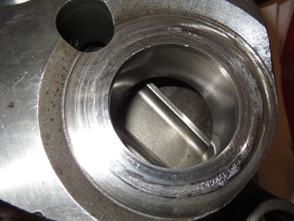
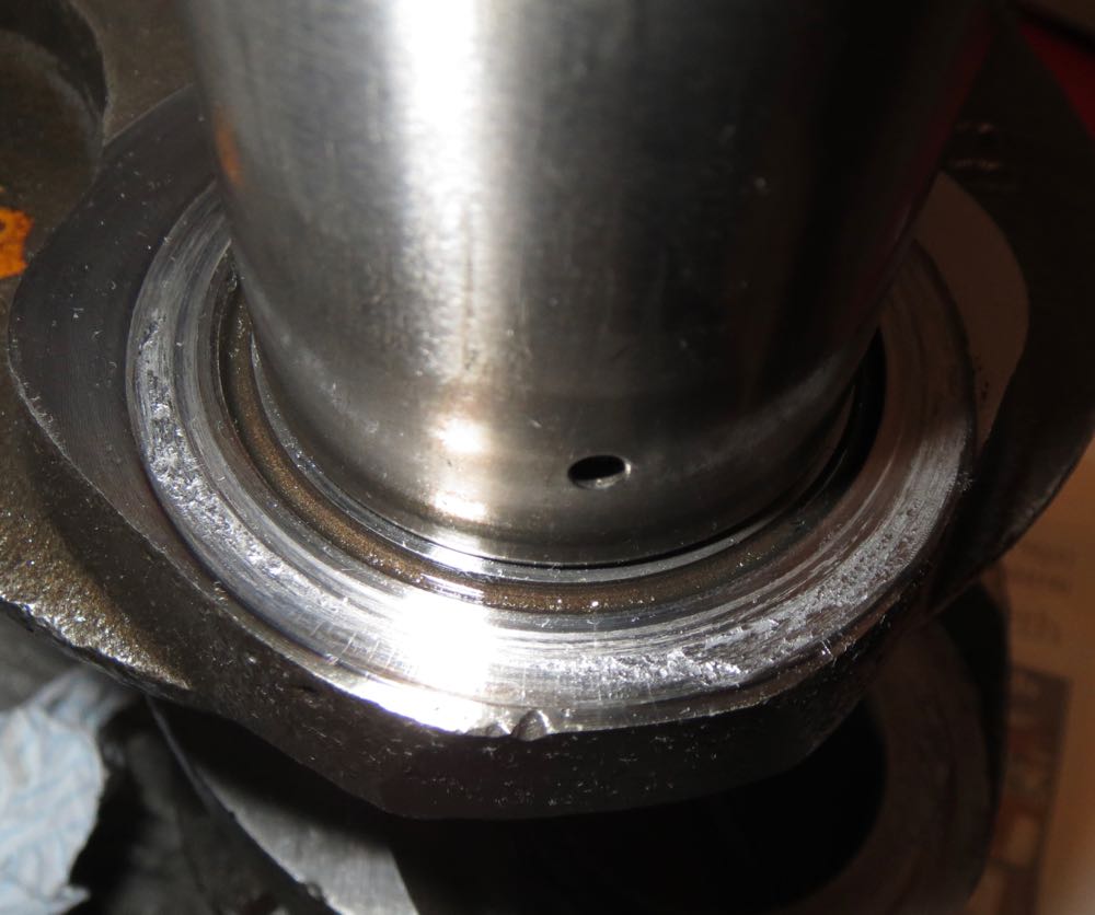
The pictures tell a story, as the rear rod has welded itself to the crankshaft webs, more so to the middle web than the rear, and there was plenty of oil, so what caused it?
It turns out the highest stresses are on the underside of the crankpins closest to the connecting rods, and the residual stresses in the interference are additive, such that the metal yields, and causes the crankshaft to flex. At low to mid speeds these are highest from the compressive forces of combustion, and later as the revs increase the inertial loads are greater and more destructive.
On inspection and relating to other roller bearing engines, the crankshaft to connecting rod side clearances are very low, at around 0.1mm, whereas most motorcycles run at around 0.4-0.7mm. As you open the clearances up, you need more oil flow to compensate for the losses, but that's no bad thing, as it can benefit other areas of the engine, and Brian's engine had a lot of oil on the underside of both pistons, and there was no discolouration under the crown either. In fact they had a rich golden syrup like colour, which is a very good sign indeed.
So the flexing of the crankshaft was due to the "blipping" of the throttle and the harmonics it introduced, and these combined fatally and killed the crankshaft, but it doesn't happen to a standard crankshaft, so what's different.
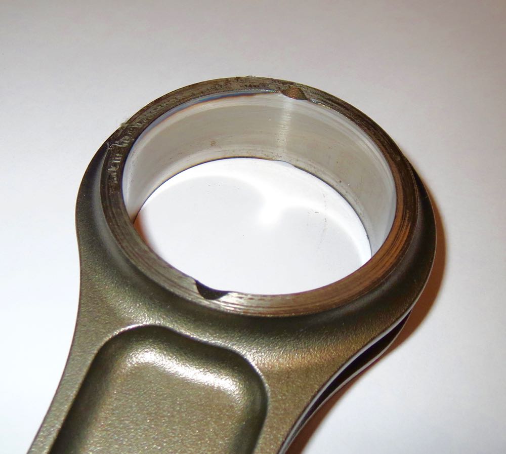
Well, the clue is here in this picture, a sleeved crankpin.
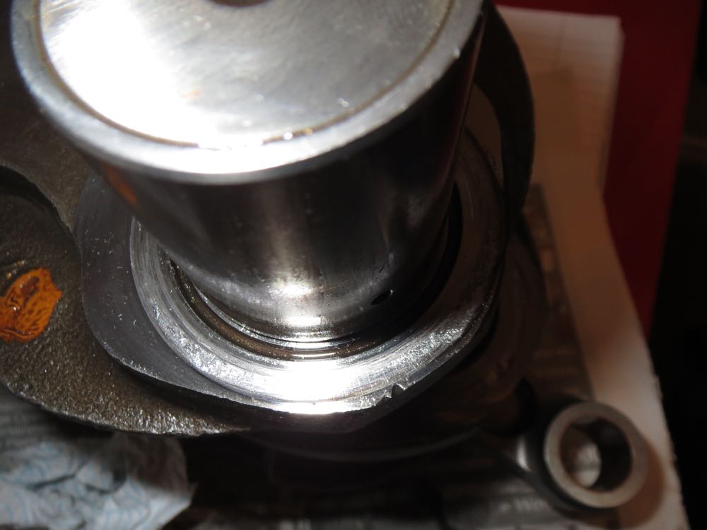
It turns out the bending moment of a round bar is proportional to the diameter to the power of 4, or D^4, which means if a 40mm bar has a bending moment of 100%, a 35mm bar has 59% of this value.
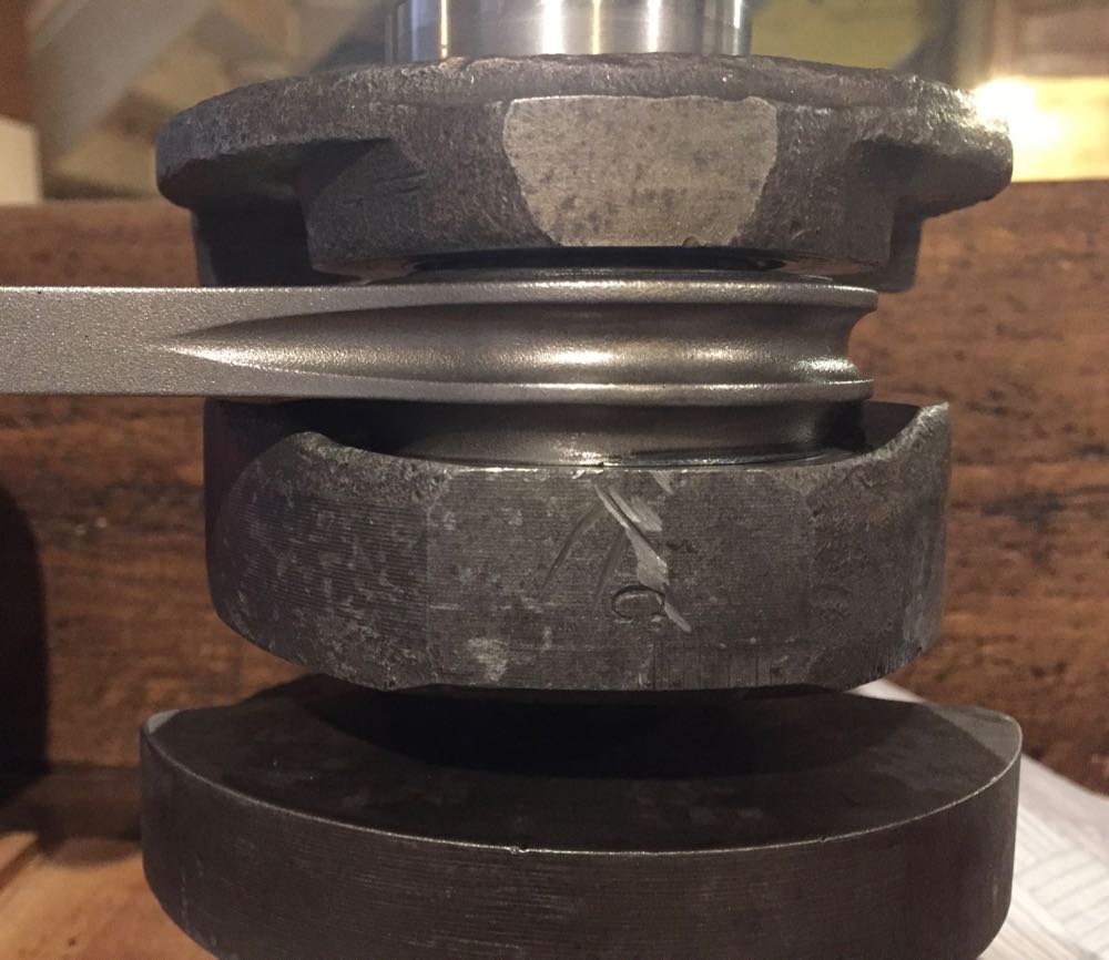
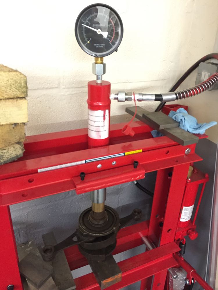
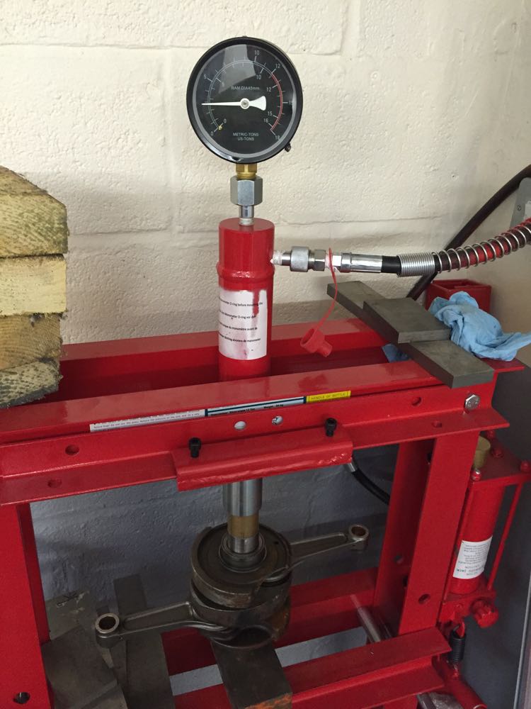
This is a huge reduction, and why you don't want to go do a sleeved route. This was also seen in a load deflection test, that I carried out. I wanted to understand whether I could test this, so I put a old crankshaft and the reassembled damaged one, and by applying a pressure to the ends it would cause the crankshaft to flex, without brinnelling the rollers into the crank pin, and the load limit was the rotation of the connecting roads. When it was too hard to rotate the rods, as in they had locked up by the crank webs touching them, then it was time to record the pressure.
As you can see the original crankshaft assembly took 5 tonnes of pressure, and Brian's 3 tonnes or so, which is about 60% of the original, and correlates well with the physical properties.
We nipped into the shed, and I started it, and he was gobsmacked it sound so quiet on open pipes, and after I released the choke, I left the engine on a slow idle to warm up. After a cup of tea, we went back to the shed, and I checked the exhausts and cylinders, and started to gently open the throttle. Then I dip three short blips on the throttle, "broom, broom, broom", and on the third blip just as I let the throttle go, there was an sudden "dink".
He looked at me, I looked at him, and just said, "It's seized, most odd". That was when the engine was almost ready to go in Brian's car, and all it needed were a few detailed tweaks, a clean with strip down and a rebuild.
In a few hours the engine was stripped, the crankshaft split, and the cause inspected. It was a mystery, how could this crankshaft fail? It had only done 27 hours running, and how come the rod had friction welded itself to the crank web?
The pictures tell a story, as the rear rod has welded itself to the crankshaft webs, more so to the middle web than the rear, and there was plenty of oil, so what caused it?
It turns out the highest stresses are on the underside of the crankpins closest to the connecting rods, and the residual stresses in the interference are additive, such that the metal yields, and causes the crankshaft to flex. At low to mid speeds these are highest from the compressive forces of combustion, and later as the revs increase the inertial loads are greater and more destructive.
On inspection and relating to other roller bearing engines, the crankshaft to connecting rod side clearances are very low, at around 0.1mm, whereas most motorcycles run at around 0.4-0.7mm. As you open the clearances up, you need more oil flow to compensate for the losses, but that's no bad thing, as it can benefit other areas of the engine, and Brian's engine had a lot of oil on the underside of both pistons, and there was no discolouration under the crown either. In fact they had a rich golden syrup like colour, which is a very good sign indeed.
So the flexing of the crankshaft was due to the "blipping" of the throttle and the harmonics it introduced, and these combined fatally and killed the crankshaft, but it doesn't happen to a standard crankshaft, so what's different.
Well, the clue is here in this picture, a sleeved crankpin.
It turns out the bending moment of a round bar is proportional to the diameter to the power of 4, or D^4, which means if a 40mm bar has a bending moment of 100%, a 35mm bar has 59% of this value.
This is a huge reduction, and why you don't want to go do a sleeved route. This was also seen in a load deflection test, that I carried out. I wanted to understand whether I could test this, so I put a old crankshaft and the reassembled damaged one, and by applying a pressure to the ends it would cause the crankshaft to flex, without brinnelling the rollers into the crank pin, and the load limit was the rotation of the connecting roads. When it was too hard to rotate the rods, as in they had locked up by the crank webs touching them, then it was time to record the pressure.
As you can see the original crankshaft assembly took 5 tonnes of pressure, and Brian's 3 tonnes or so, which is about 60% of the original, and correlates well with the physical properties.
