Aug 2013
Repairing the damaged cylinder
22/08/13 00:50
This is a close up of the damage to the cylinder, and you can see the broken valve head has caused some nasty impacts, so I decided to scrap the cylinder.
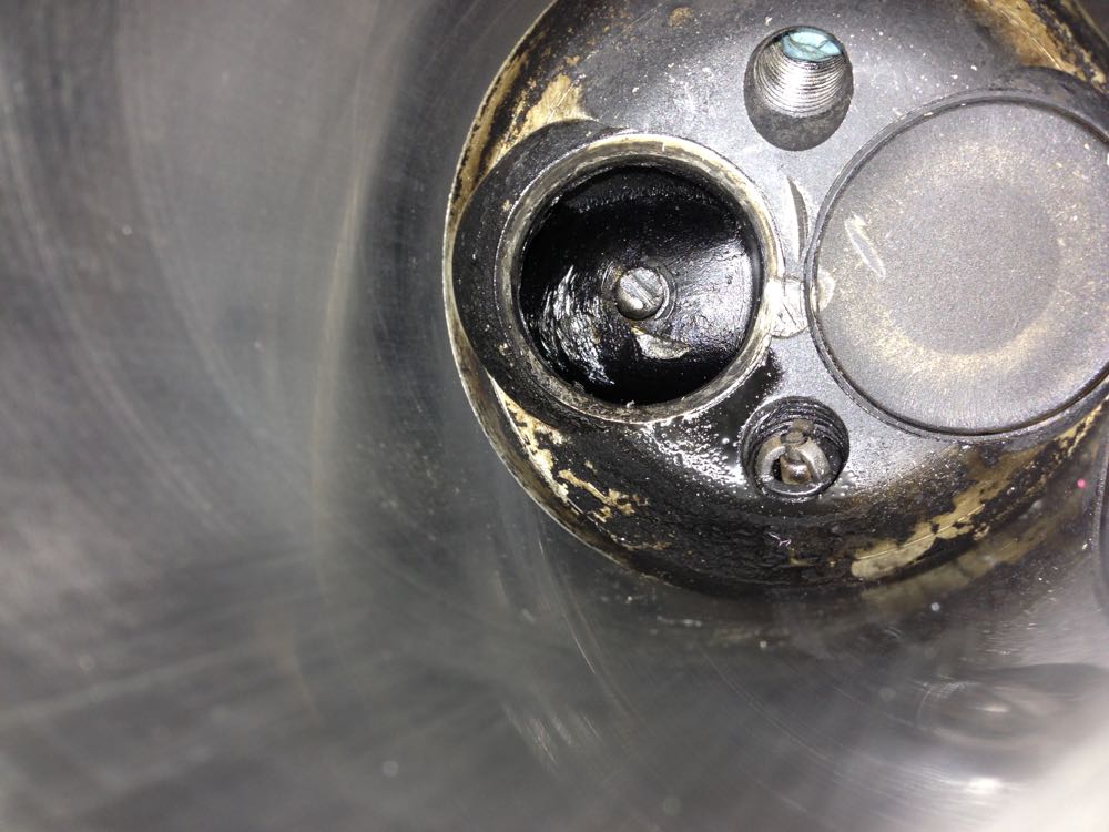
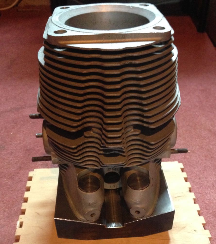
As these are all in one cylinders and heads, as in very deep, it's a mess trying to get down to weld and machine afterwards, and I thought it wasn't worth the effort. I found another cylinder that was a similar size with the liner removed, and I will update this.
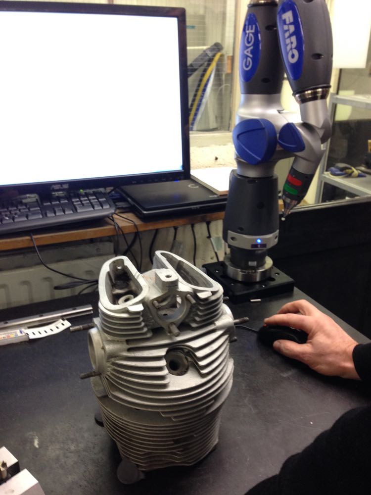
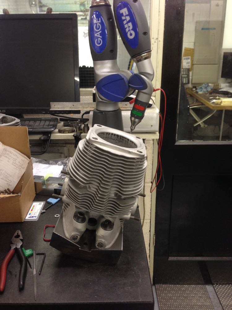
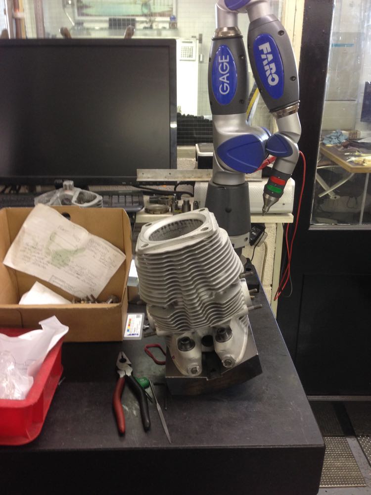
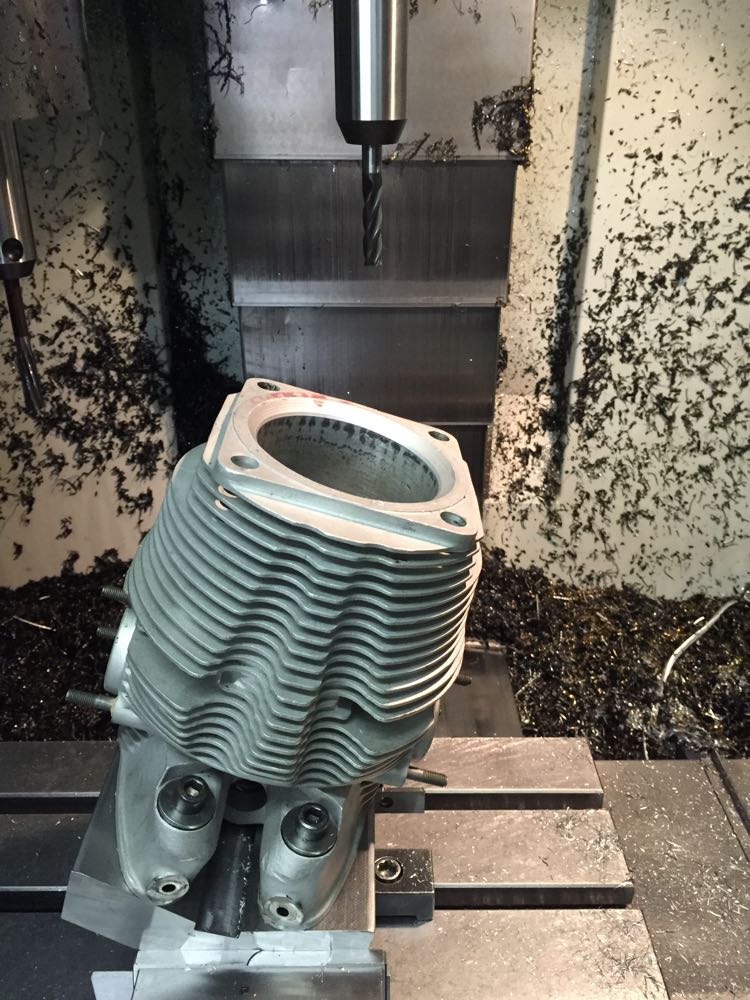
First up I had to make a jig for the CNC machine to hold the cylinder in the desired position, and so a flame cut lump of metal was ordered, then I needed the dimensions for the CAD model,and this is where a Faro arm comes in..
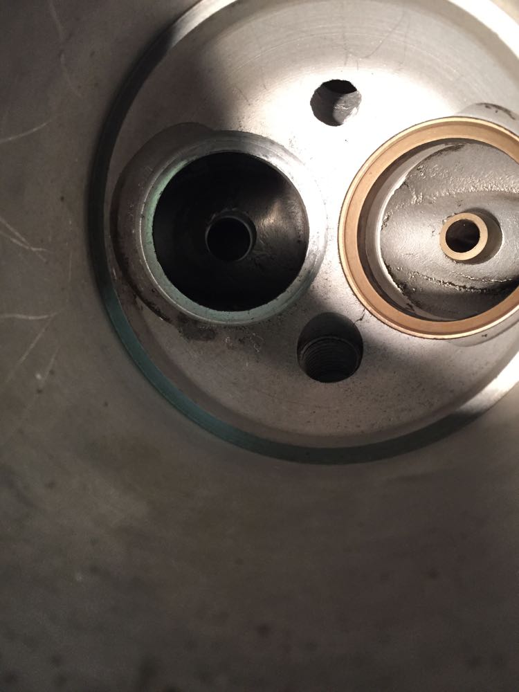
Next up a partial twin plugged cylinder had the standard exhaust seat removed as a precaution, as well as the valve guide later on. Notice all the deposits that oozed out of the seat removal process, which tells you this one was loose.
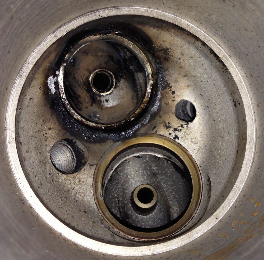
…and after a clean, and you can seat the exhaust valve seat recess fretting marks…

Now to create a test piece, to double check the accuracy of the jig, which had been CNC'ed from the CAD model I drew up previously.
Then time to double check the accuracy on the Faro again, but this is now September 2014. I have been working on other stuff whilst trying to progress this.
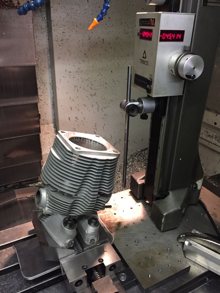
Another check a few weeks later, to make sure the milling machine can reach the bottom of the combustion chamber.
After all this there was a twist in the jig, and it needed to be machined, but at least it was spotted before any cylinders were done.
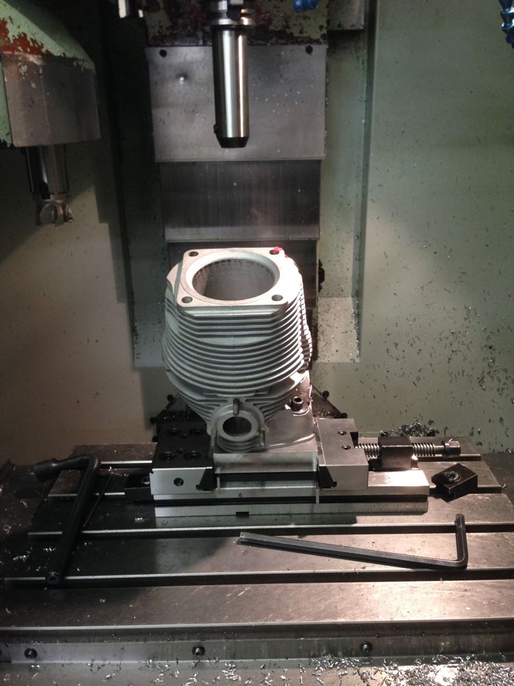
Finally in early December 2014, it is time to machine the new valve seat recess in the combustion chamber.
Then a quick check of the seat size, and a tweak to the final cut.
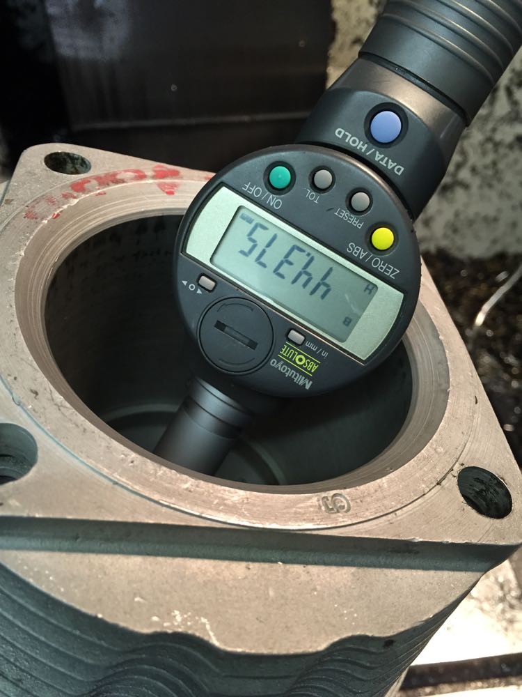
…and this is the finished seat recess cut into the head, with concentric valve guide hole done at the same time too.
After Christmas, it was time to make the guides and other stuff.
As these are all in one cylinders and heads, as in very deep, it's a mess trying to get down to weld and machine afterwards, and I thought it wasn't worth the effort. I found another cylinder that was a similar size with the liner removed, and I will update this.
First up I had to make a jig for the CNC machine to hold the cylinder in the desired position, and so a flame cut lump of metal was ordered, then I needed the dimensions for the CAD model,and this is where a Faro arm comes in..
Next up a partial twin plugged cylinder had the standard exhaust seat removed as a precaution, as well as the valve guide later on. Notice all the deposits that oozed out of the seat removal process, which tells you this one was loose.
…and after a clean, and you can seat the exhaust valve seat recess fretting marks…
Now to create a test piece, to double check the accuracy of the jig, which had been CNC'ed from the CAD model I drew up previously.
Then time to double check the accuracy on the Faro again, but this is now September 2014. I have been working on other stuff whilst trying to progress this.
Another check a few weeks later, to make sure the milling machine can reach the bottom of the combustion chamber.
After all this there was a twist in the jig, and it needed to be machined, but at least it was spotted before any cylinders were done.
Finally in early December 2014, it is time to machine the new valve seat recess in the combustion chamber.
Then a quick check of the seat size, and a tweak to the final cut.
…and this is the finished seat recess cut into the head, with concentric valve guide hole done at the same time too.
After Christmas, it was time to make the guides and other stuff.
