New crankshaft design
22/04/16 01:21
Bench testing the engine
22/04/16 01:20
DCNF carburettor modifications
22/04/16 01:20
Investigate piston to valve clearance
22/04/16 01:20
Investigate the valve gear return spring tension
22/04/16 01:20
Programmable ignition using multi toothed wheel
22/04/16 01:20
Crankshaft failure
08/02/16 01:21
A most disappointing start to the day, as I had a friend come round to the house, and he asked how the engine was going, so I said, "Have a look for yourself".
he nipped into the shed, and I started it, and he was gobsmacked it sound so quiet on open pipes, and after I released the choke, I left the engine on a slow idle to warm up. After a cup of tea, we went back to the shed, and I checked the exhausts and cylinders, and started to gently open the throttle. Then I dip three short blips on the throttle, "broom, broom, broom", and on the third blip just as I let the throttle go, there was an sudden "dink".
He looked at me, I looked at him, and just said, "It's seized, most odd". That was when the engine was almost ready to go in Brian's car, and all it needed were a few detailed tweaks, a clean with strip down and a rebuild.
In a few hours the engine was stripped, the crankshaft split, and the cause inspected. It was a mystery, how could this crankshaft fail? It had only done 27 hours running, and how come the rod had friction welded itself to the crank web.
Seat cutting woes
03/05/15 00:50
Making yet another cylinder
27/04/15 00:30
So lets start again! :(
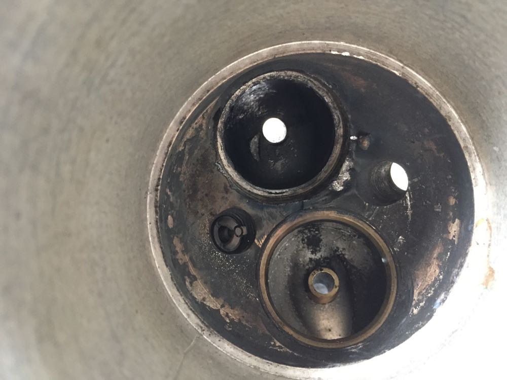
Then it was off to the CNC shop and get it machined using the same jig & fixture.
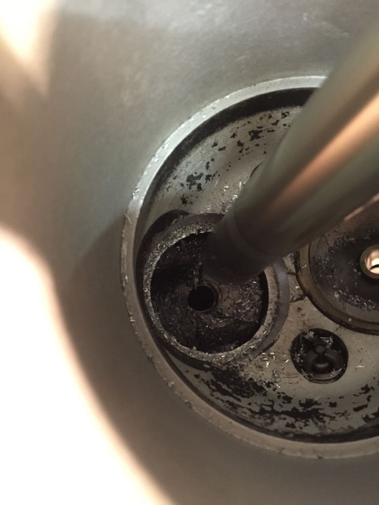
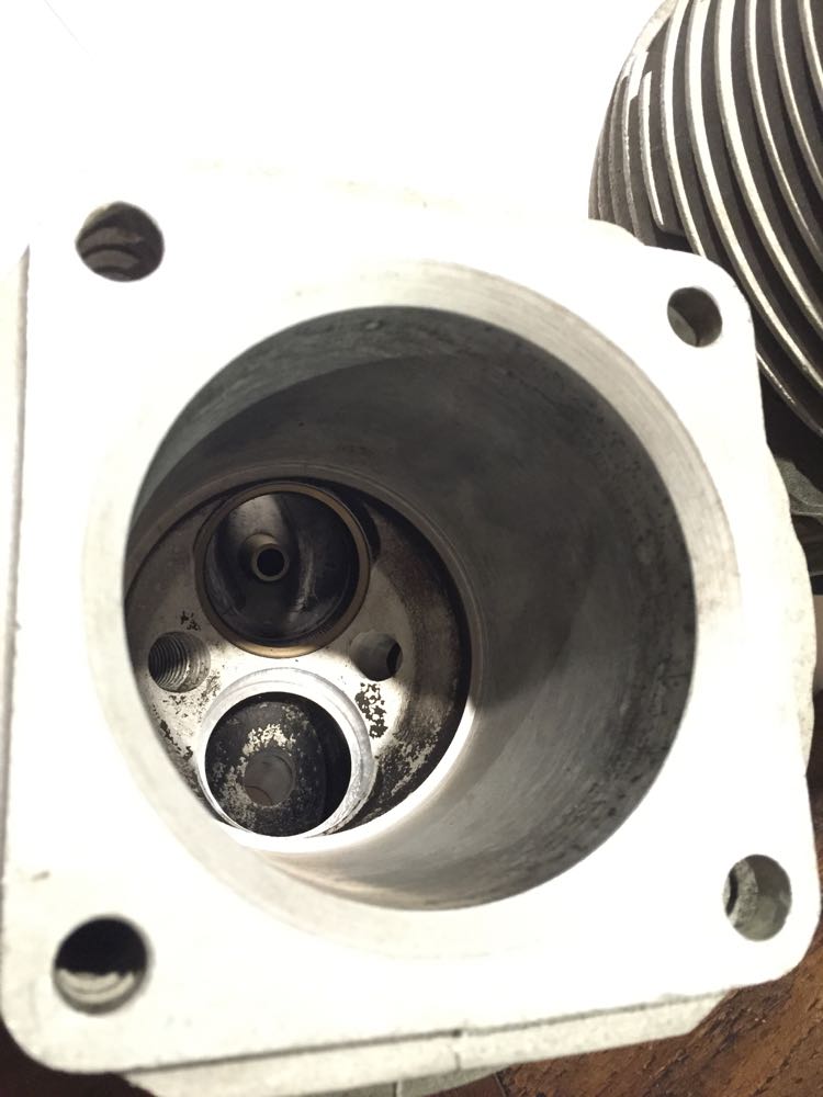
A day later, the seat was cold enough and the cylinder was heated, and the seat and guide dropped in place. in the picture below, you can see the heat from the cylinder blueing up the seat as the heat soaks back.
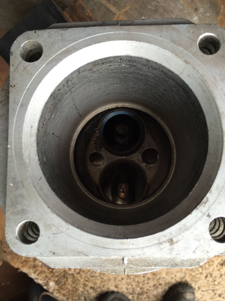
& guide

Then it was off to the CNC shop and get it machined using the same jig & fixture.


A day later, the seat was cold enough and the cylinder was heated, and the seat and guide dropped in place. in the picture below, you can see the heat from the cylinder blueing up the seat as the heat soaks back.

& guide
Making new valve guides
16/01/15 00:07
Now that the cylinder had been machined, it was time to start rebuilding it, so I purchased some oversized bronze valve guides and looked at machining them to suit. The outer diameter was sized to the reamed hole in the cylinder, and I had increased the diameter to 14mm nominal to create a good mating surface and better interference fit.
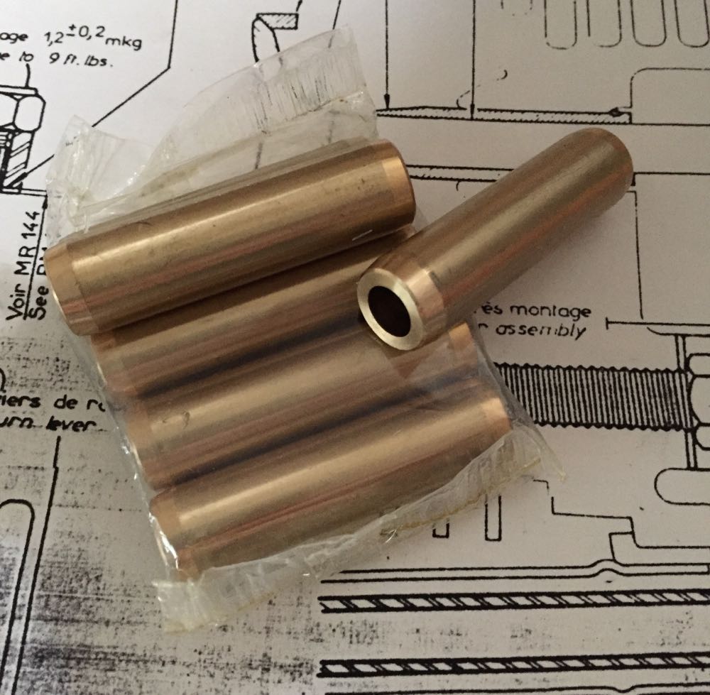
These were going to be machined later, and it was a lot later, because in Feb 2015 the valve seats arrived.
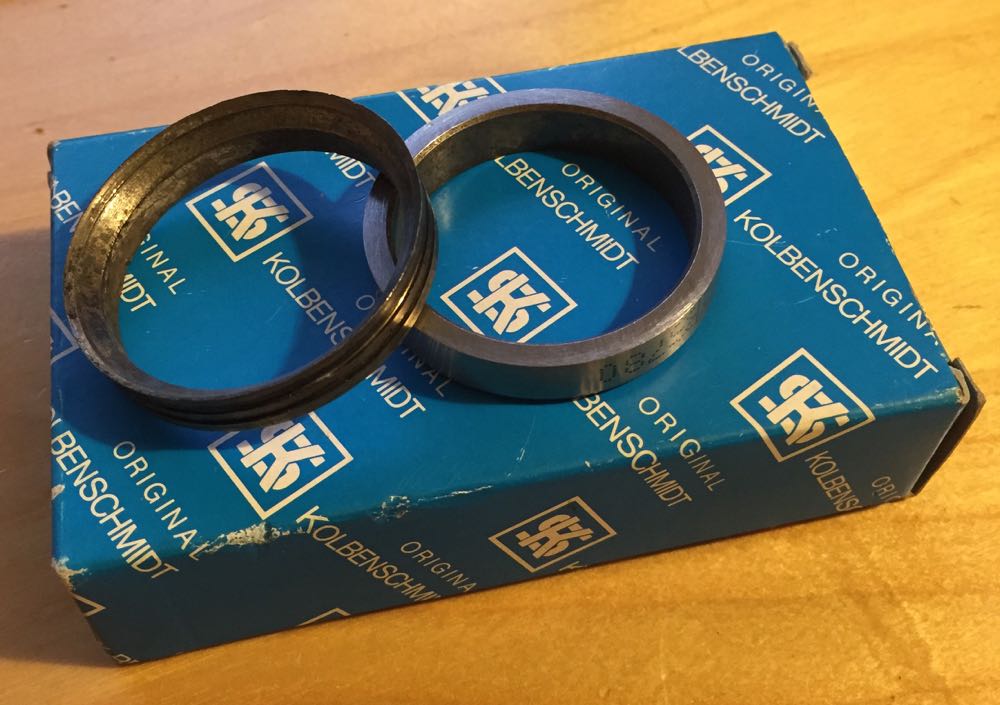
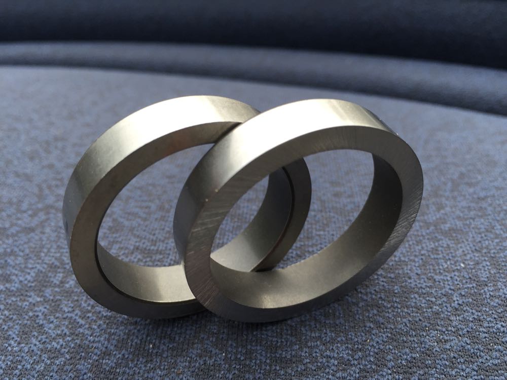
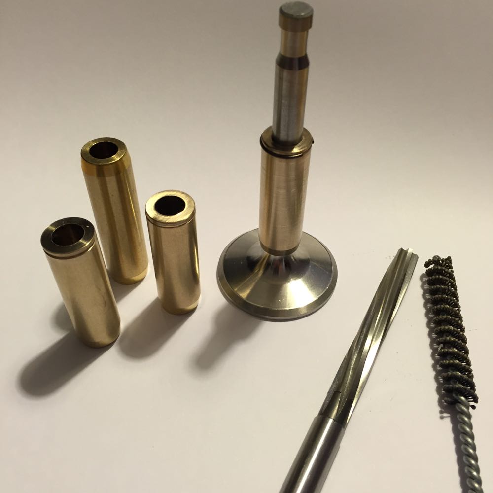
It was now March 2015, and the valves, guides and seats I was going to use were all made, as well as having a reamer ground to size, and a new FlexHone purchased, as I was using an 8.5mm Alain Lauffenburger exhaust valve. It had a similar weight to the other cylinder, but that's for another day.
New guide and seat installed, partially machined, and it's now late April 2015.
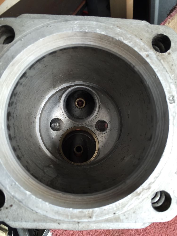
By this point there was an issue with the valve seat cutting and I had no idea what was going wrong, so I "scrapped" the cylinder, as I wasn't happy with it and had to start again.

These were going to be machined later, and it was a lot later, because in Feb 2015 the valve seats arrived.


It was now March 2015, and the valves, guides and seats I was going to use were all made, as well as having a reamer ground to size, and a new FlexHone purchased, as I was using an 8.5mm Alain Lauffenburger exhaust valve. It had a similar weight to the other cylinder, but that's for another day.

New guide and seat installed, partially machined, and it's now late April 2015.

By this point there was an issue with the valve seat cutting and I had no idea what was going wrong, so I "scrapped" the cylinder, as I wasn't happy with it and had to start again.
Repairing the damaged cylinder
22/08/13 00:50
This is a close up of the damage to the cylinder, and you can see the broken valve head has caused some nasty impacts, so I decided to scrap the cylinder.
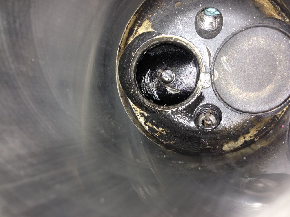
As these are all in one cylinders and heads, as in very deep, it's a mess trying to get down to weld and machine afterwards, and I thought it wasn't worth the effort. I found another cylinder that was a similar size with the liner removed, and I will update this.
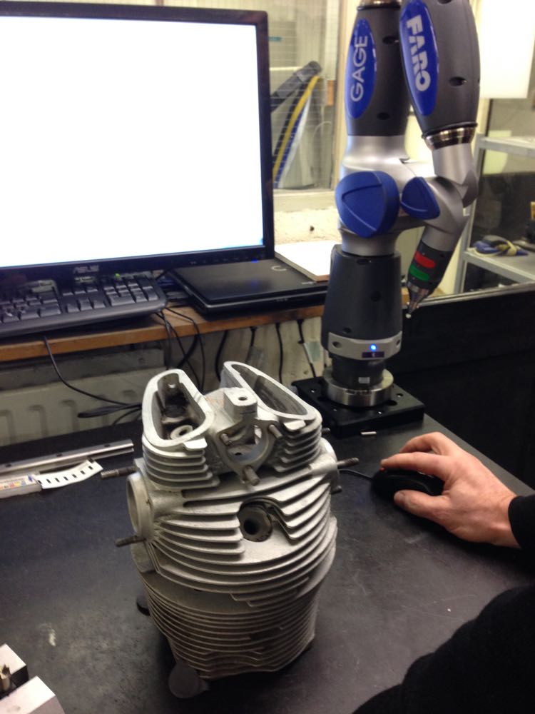
First up I had to make a jig for the CNC machine to hold the cylinder in the desired position, and so a flame cut lump of metal was ordered, then I needed the dimensions for the CAD model,and this is where a Faro arm comes in..
Next up a partial twin plugged cylinder had the standard exhaust seat removed as a precaution, as well as the valve guide later on. Notice all the deposits that oozed out of the seat removal process, which tells you this one was loose.
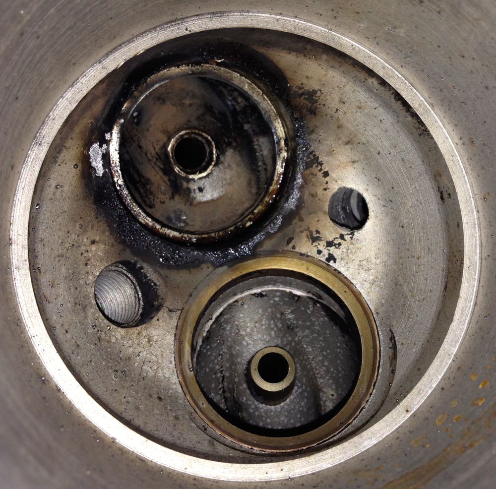
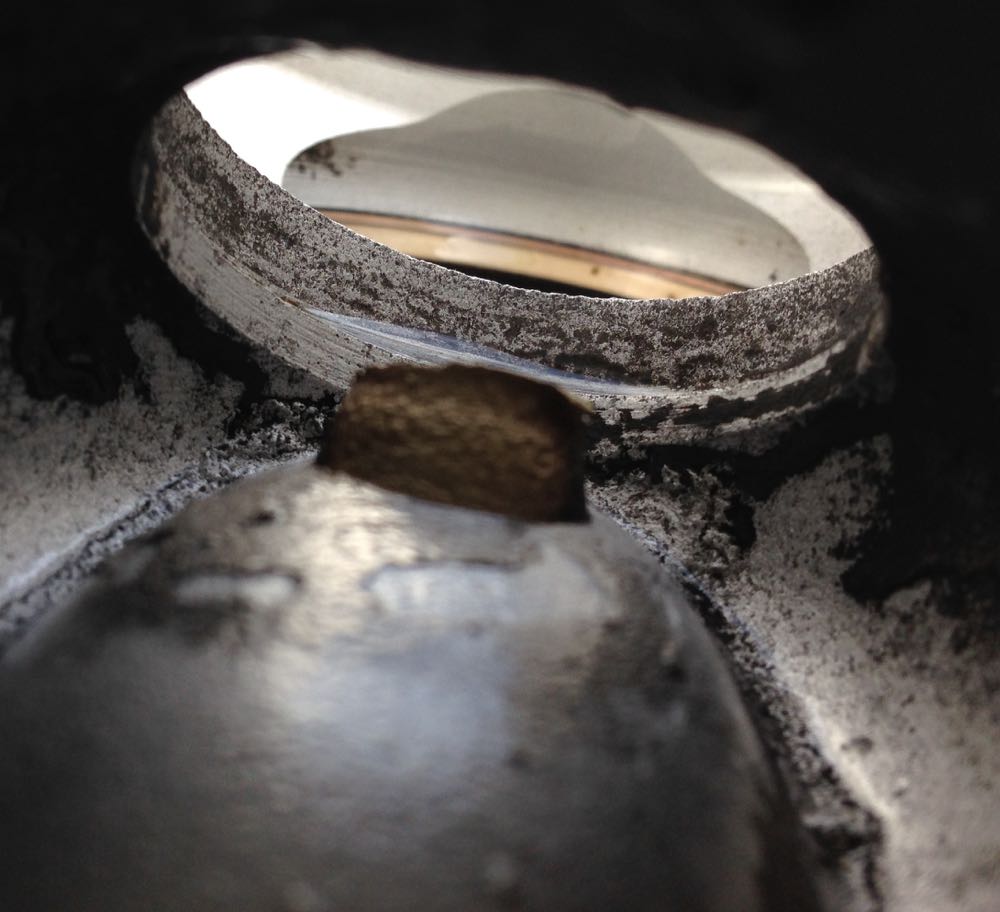
…and after a clean, and you can seat the exhaust valve seat recess fretting marks…
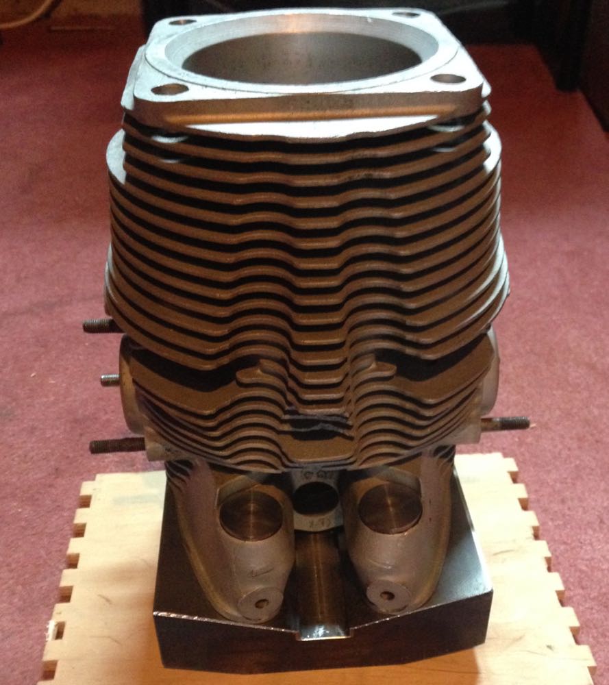
Now to create a test piece, to double check the accuracy of the jig, which had been CNC'ed from the CAD model I drew up previously.
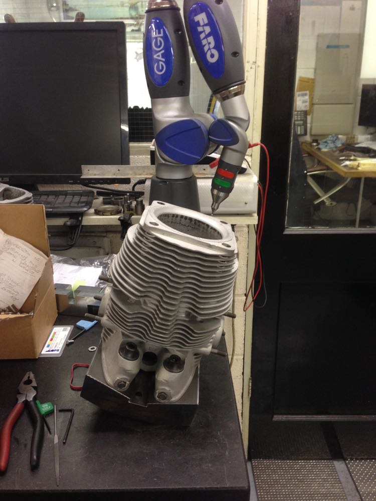
Then time to double check the accuracy on the Faro again, but this is now September 2014. I have been working on other stuff whilst trying to progress this.
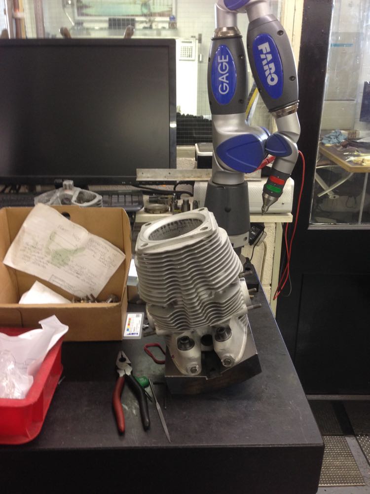
Another check a few weeks later, to make sure the milling machine can reach the bottom of the combustion chamber.
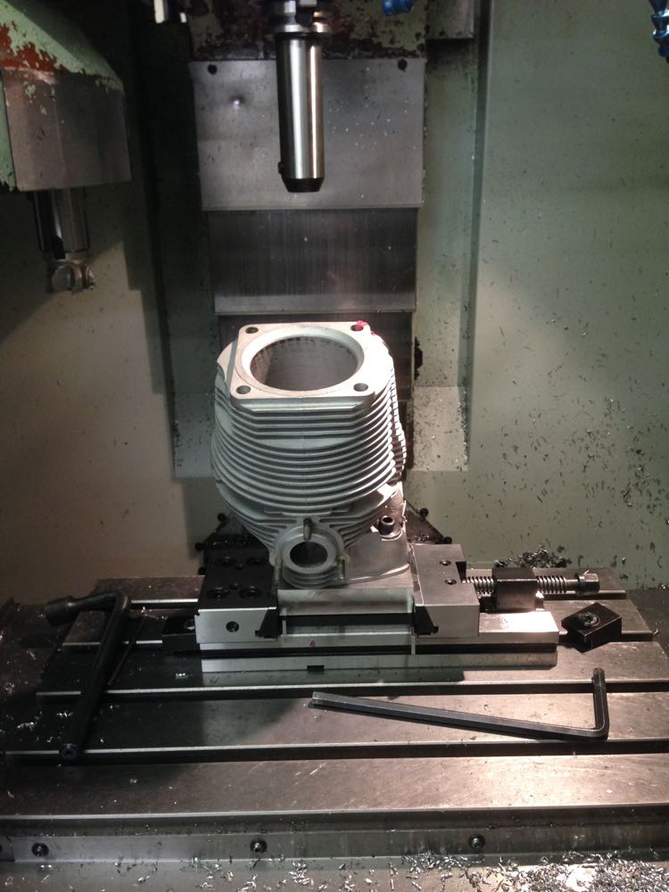
After all this there was a twist in the jig, and it needed to be machined, but at least it was spotted before any cylinders were done.
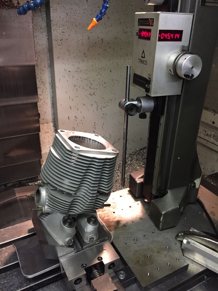
Finally in early December 2014, it is time to machine the new valve seat recess in the combustion chamber.
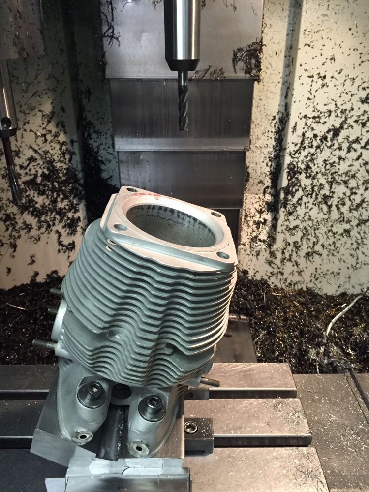
Then a quick check of the seat size, and a tweak to the final cut.
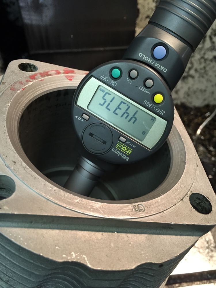
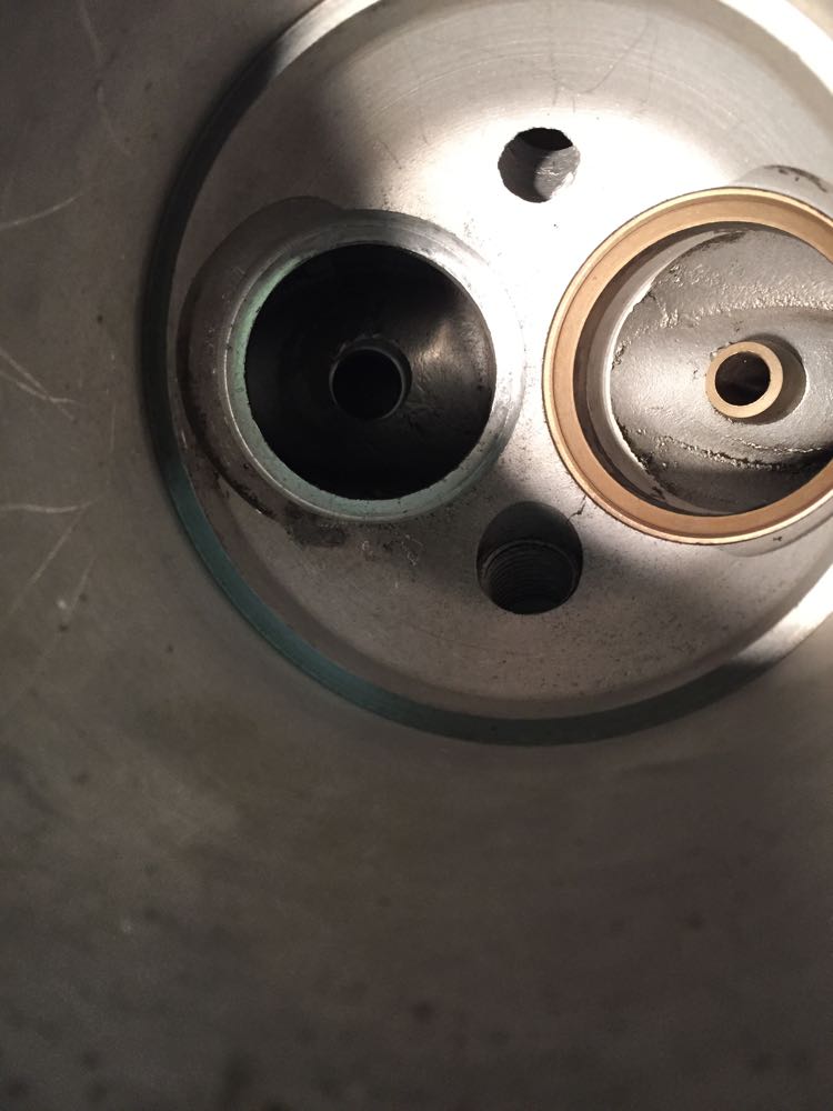
…and this is the finished seat recess cut into the head, with concentric valve guide hole done at the same time too.
After Christmas, it was time to make the guides and other stuff.

As these are all in one cylinders and heads, as in very deep, it's a mess trying to get down to weld and machine afterwards, and I thought it wasn't worth the effort. I found another cylinder that was a similar size with the liner removed, and I will update this.
First up I had to make a jig for the CNC machine to hold the cylinder in the desired position, and so a flame cut lump of metal was ordered, then I needed the dimensions for the CAD model,and this is where a Faro arm comes in..

Next up a partial twin plugged cylinder had the standard exhaust seat removed as a precaution, as well as the valve guide later on. Notice all the deposits that oozed out of the seat removal process, which tells you this one was loose.

…and after a clean, and you can seat the exhaust valve seat recess fretting marks…

Now to create a test piece, to double check the accuracy of the jig, which had been CNC'ed from the CAD model I drew up previously.

Then time to double check the accuracy on the Faro again, but this is now September 2014. I have been working on other stuff whilst trying to progress this.

Another check a few weeks later, to make sure the milling machine can reach the bottom of the combustion chamber.

After all this there was a twist in the jig, and it needed to be machined, but at least it was spotted before any cylinders were done.

Finally in early December 2014, it is time to machine the new valve seat recess in the combustion chamber.

Then a quick check of the seat size, and a tweak to the final cut.

…and this is the finished seat recess cut into the head, with concentric valve guide hole done at the same time too.

After Christmas, it was time to make the guides and other stuff.
The next generation engine
28/07/13 00:50
After the sudden failure of the 2014 engine on that uphill stretch of the M20, when the little 24CT was cruising at 6000 rpm on part throttle, I decided I needed a new direction.
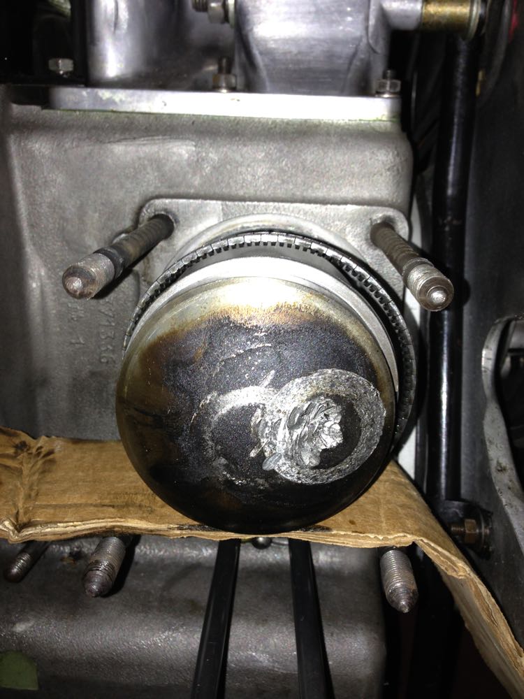
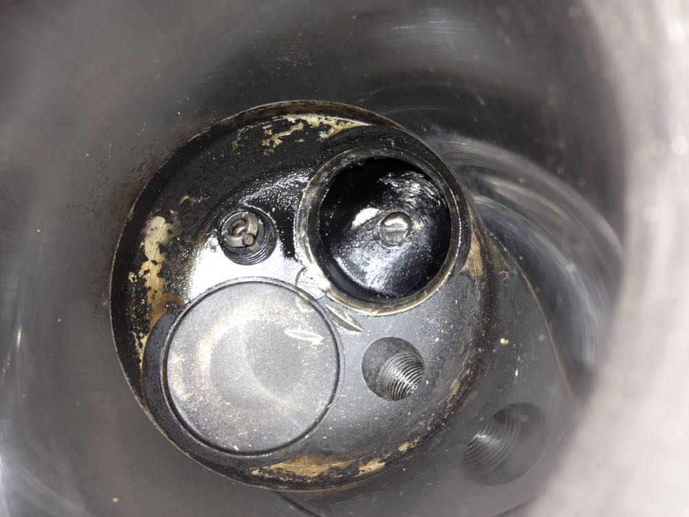
On examination the valve had failed and this was despite having adequate clearance, or so I thought at the time. Unfortunately, I was to discover that the valve train was rather inept at controlling the valves, and what had happened was the heavier exhaust valve had hit the piston, and on the affected cylinder it was more severe. I was only found out about this several months later, when I inspected the other cylinder.
So what were the plans for the 2016 engine.
1. Repair the damaged cylinder.
2. Investigate the piston to valve clearance, and increase this.
3. Investigate the valve gear return spring tension.
4. Fit the later programmable electronic ignition with multi toothed trigger wheel
5. Refine the double sump & filter set up.
6. Bench test the engine, prior to installing in the car.
