Mar 2012
Panhard pistons ordered
24/03/12 12:07
I have ordered a minimum set of pistons today, which is 12 number or 6 sets in total. The price for this batch has been fixed at a special developmental price, the next batch will cost £350 for a complete set of two pistons, rings, pin and clips.
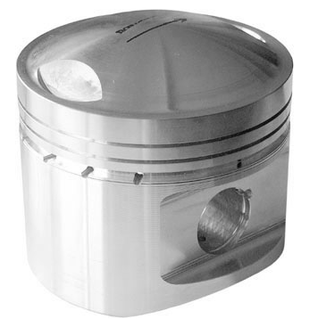
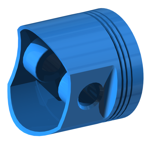
They are expected to arrive around the 18th June 2012, and I will add more details as I get them, but the picture above shows the basic design. The actual piston is based on a 1950’s car forging, uses readily available motorcycle rings, but the cylinder bore will be 85.3-85.4 mm, depending on the ring set I can get for this batch.
They will be higher compression capable, lightweight 3 ringed pistons, with a 3/4” or 19.05 mm pin diameter. This will require a special interference fit conversion bush to be made for the connecting rod little end, which is an additional cost item for the early adopters.
Panhard rear bearing oilway modification
18/03/12 20:49
I managed a little more of the engine, after getting sidetracked with the Whatton Boring Bar. Here’s the older design M6 on the left, and the newer M8S rear bearing support casting on the right. There is a difference in hole diameter at the inlet, and more of a restriction at the other end too.
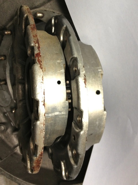
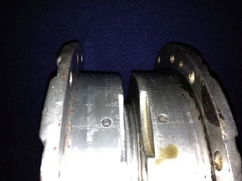
This is the left hand M6 casting after being modded at the inlet side, and also at the outlet
.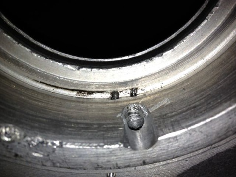
The hole has been smoothed and with a dummy bearing fitted you can see the difference in surface area, versus the older design underneath. What is not apparent is the hole is only 3mm in diameter just under the bearing on this M6 casting.
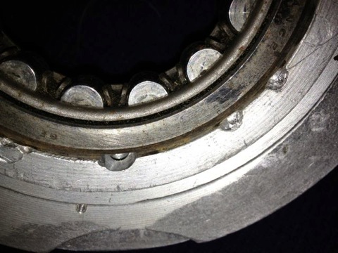
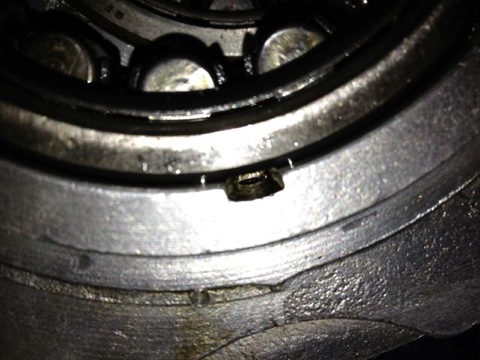
With the improved design of the oil circuit, especially the mod to the camshaft gallery, more oil will flow into the bearings and also be at a higher pressure. Next up the oil light piston and the rear seal mods.


This is the left hand M6 casting after being modded at the inlet side, and also at the outlet
.

The hole has been smoothed and with a dummy bearing fitted you can see the difference in surface area, versus the older design underneath. What is not apparent is the hole is only 3mm in diameter just under the bearing on this M6 casting.


With the improved design of the oil circuit, especially the mod to the camshaft gallery, more oil will flow into the bearings and also be at a higher pressure. Next up the oil light piston and the rear seal mods.
Panhard pistons and a redesign
11/03/12 21:16
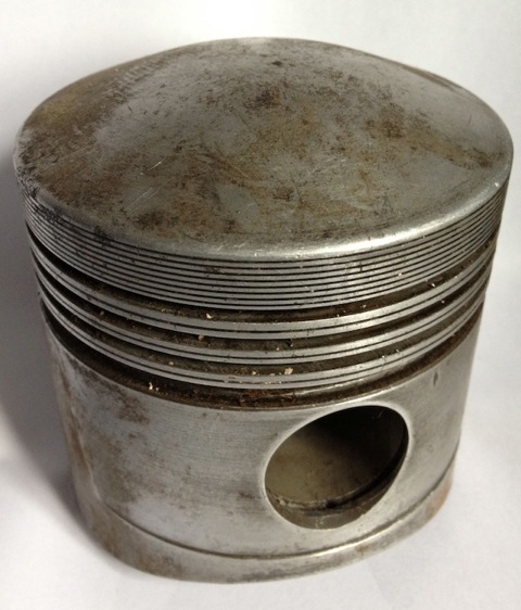
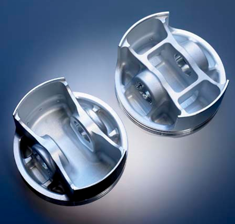
Panhard pistons are quite heavy and bulky items compared to todays’ equivalents, examples shown below, but that’s because the piston has to be domed to make the compression high enough due to their hemispherical combustion chamber layout, whereas modern day pistons have minimal surface areas applied to the piston and combustion volumes, thinner rings and latterly thermal coatings, which allow for even thinner sections.
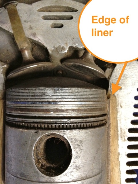
The biggest limiting factor is the close proximity of the top ring to the end of the steel liner, and as shown below the top ring is quite far down the piston, around 10mm from the top deck.
These engines are from the junk pile, but they still have their uses, as this piston was cut up to show the typical cross-sectional areas that exist within the original. There are more than one type of Panhard piston used in the flat twin engine, but this is the later 4 ringed type, that was cut up today.
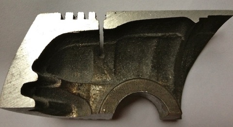
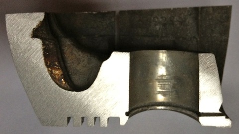
Why is this done? I need to understand why the naked Panhard piston weighs 505 grams, when my target weight for a heavily domed piston is sub 400grams, which is double the weight of a single cylinder Supermotard piston from 2002, and probably three times heavier than a complete MotoGP piston!
PANHARD PISTON REDESIGN
I need to replace the pistons and rebore Brian’s cylinder, as this engine will represent a rejuvenated and refreshed Panhard engine using mostly OEM parts. The original pistons are only available in certain sizes, and the design of them isn’t really good practice nowadays.
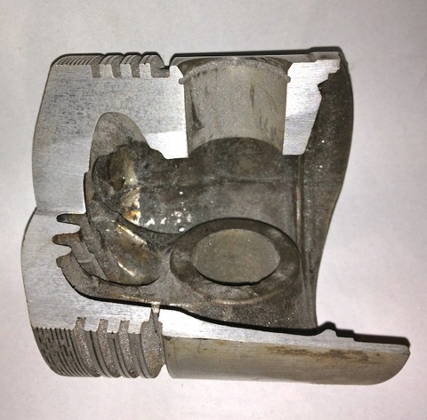
There is little that can be done about the domed area or the piston pin position, because these are factors of the combustion chamber, and also the crankcase limits using longer rods. Obviously you can shorten the cylinders, but it is a lot of work, that few people will want to pay for. Under examination, it is fair to see that the tall & shallow OEM ring construction is at odds with the more modern thin & deep thinking. The oil scraper functions have been analysed and there are several upgrade options that can be used too. Piston skirt design, and gudgeon or piston pin location strategies have all changed, as well as different materials and coating technologies, which all enhance performance or give longer life when used in marginal conditions. So ideally finding a modern day piston that would fit would seem to be the answer, but although I have known about several pistons that I can use, they all have potential issues around the top ring placement and the fixed liner.
On reflection it would be more logical to design a replacement then, but what benefits would this give?
Obviously, this will give a slight capacity increase, as you are essentially reconditioning the standard Panhard liner, which has a finite thickness, but what about the tapered bores. Hmmm, we’ll pass on this for a minute while considering other points.
Fundamentally the piston should be a lot lighter, which will reduce crankshaft loads and prolong the life of the rotating elements at higher rpms. The ring technology has changed, so these get lighter and generally use combustion pressure to effect a seal. The thinner rings also have less friction and can reduce crankcase compression blowby, but the cylinders have to be finished to a higher standard for the rings to seal correctly.
There is a possibility that an offset piston pin can be used, which reduces piston noise when the engine is warm, and more importantly reduces the shock loading on the connecting rod, by spreading the reciprocating load changes over a fractionally wider area of rotation. The slight offset or bias to the exhaust side of the piston also reduces cylinder bore wear, but this is not used in racing, because the engines are maintained more frequently, so most forged pistons don’t use this.
Lastly, there is a wealth of coatings technology that can be applied, although this does add expense to the final product, it does offer protection from nasty combustion events, and does improve reliability.
These doodles are some of my thoughts from today, and obviously I can reduce the sections some more, but the target weight of sub 400grams looks like it will be achievable now.
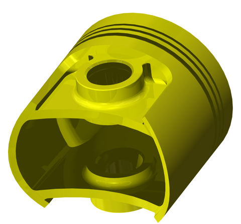
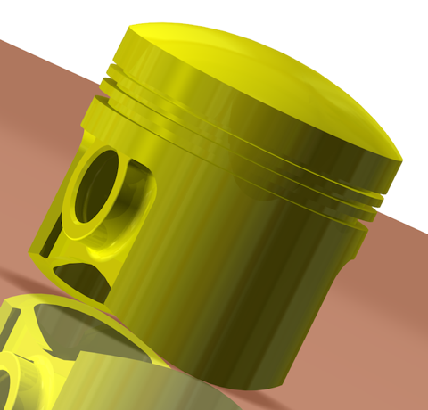
I need to do some finite element stress analysis to take it further, but hopefully those following this will understand the direction the engine is taking.
PS The tapered bores will be for another blog post.
Panhard crankcase rear bearing support
10/03/12 20:58
I was going to remove the rear NU209 main bearing on the engine, but needed to make a small adaptor to measure the end float on the crankshaft before I do so. This particular engine has a little bit of movement in the rear crank pin, and I need to find out why it has moved.
The early M6 back plate is on the left and the later M8 is on the right.

The holes are bigger on the later one, which means more oil can be supplied to the rear bearing. After measuring these it equates to an improvement of 15% over the earlier design.
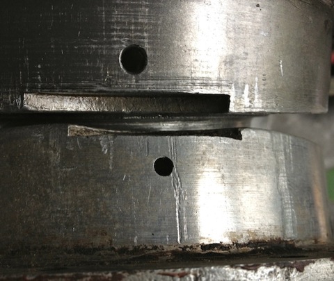
Brian’s engine will be increased further still, to match the front crankcase drilling. In the meantime I am waiting for another plate as Brians is damaged around the rear seal area, and it looks like something, a fastener possibly, has got between the flywheel and the rear plate!
The early M6 back plate is on the left and the later M8 is on the right.

The holes are bigger on the later one, which means more oil can be supplied to the rear bearing. After measuring these it equates to an improvement of 15% over the earlier design.

Brian’s engine will be increased further still, to match the front crankcase drilling. In the meantime I am waiting for another plate as Brians is damaged around the rear seal area, and it looks like something, a fastener possibly, has got between the flywheel and the rear plate!
Panhard crankcase front oil drilling reinstated
04/03/12 15:09
Next up to bring Brian’s engine up to date with the oil supply modifications is restoring the earlier oil supply method, but this time bypass all the negatives.
The later engines didn’t have this option, as can be seen here.
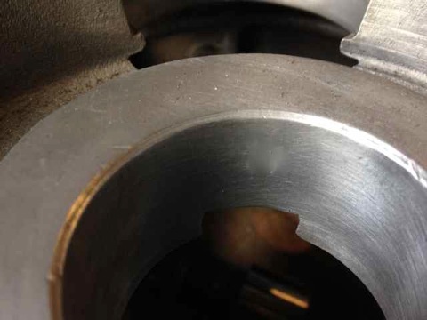
The original engines had this oil feed visible above the camshaft bore at the very front of the crankcase, which is shown below. As the camshaft rotates this drilling is filled two times per camshaft revolution, and after this it passes underneath the bearing and jumps into the slingers. Some oil splashes back and passes through the main bearing, but the rest is accelerated by the slingers on the crank web, and passes through the big end bearing before exiting and splash lubricating the little end.
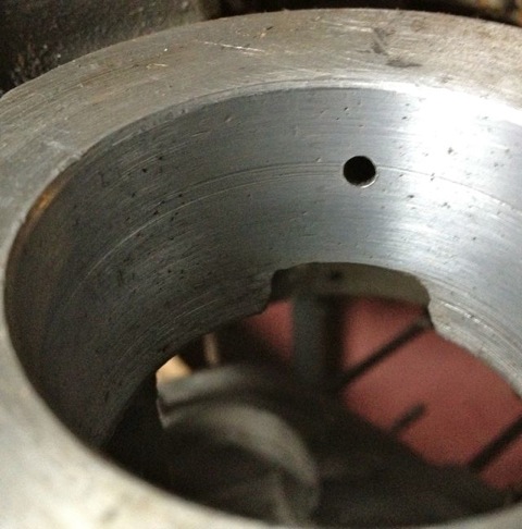
Unfortunately this hole is too small, and it led to a 50% reduction in flow rate over the rear, which is why I mod the front like so.
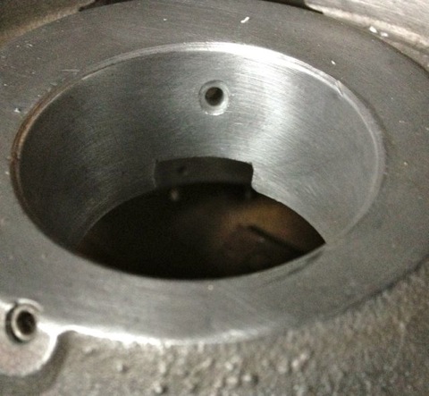
It might not be obviously apparent from the pictures, but the hole size is now 6mm diameter, whereas the one above is just 4mm. This new oil feed now matches the camshaft aperture, so that all openings, front and rear are timed equally at the rotating surfaces. The 4mm diameter hole of the earlier design will have to be enlarged to 5mm, as the rear oil feed is actually 5mm in diameter internally, but at first it is more important to get the hole in the right position, and work from this.
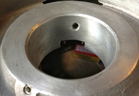
The internal oil feed pictured above now opened up to 5mm diameter, which is 50% bigger than the OEM drilling on the earlier engines. This new size matches that of the original rear bearing feed, which should equalise the flow rates. Next up, modifying the aluminium rear main bearing support casting to take a double lipped oil seal.
The later engines didn’t have this option, as can be seen here.

The original engines had this oil feed visible above the camshaft bore at the very front of the crankcase, which is shown below. As the camshaft rotates this drilling is filled two times per camshaft revolution, and after this it passes underneath the bearing and jumps into the slingers. Some oil splashes back and passes through the main bearing, but the rest is accelerated by the slingers on the crank web, and passes through the big end bearing before exiting and splash lubricating the little end.

Unfortunately this hole is too small, and it led to a 50% reduction in flow rate over the rear, which is why I mod the front like so.

It might not be obviously apparent from the pictures, but the hole size is now 6mm diameter, whereas the one above is just 4mm. This new oil feed now matches the camshaft aperture, so that all openings, front and rear are timed equally at the rotating surfaces. The 4mm diameter hole of the earlier design will have to be enlarged to 5mm, as the rear oil feed is actually 5mm in diameter internally, but at first it is more important to get the hole in the right position, and work from this.

The internal oil feed pictured above now opened up to 5mm diameter, which is 50% bigger than the OEM drilling on the earlier engines. This new size matches that of the original rear bearing feed, which should equalise the flow rates. Next up, modifying the aluminium rear main bearing support casting to take a double lipped oil seal.
Panhard crankcase camshaft gear oil level
04/03/12 12:24
A little mod that improves oil quality, reduces heat build up in the oil, and improves pumping losses to the engine. At the moment the Panhard timing case oil level is determined by the hi level drainage points shown here or leaking past the front main bearing.
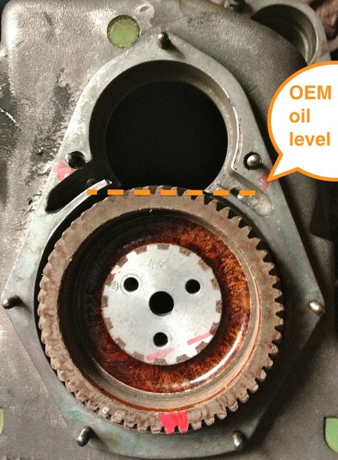
Normal practice for a splash lubricated gear is to have no more than a third of gear diameter immersed, so why Panhard did this surprises me. Originally they had a fibre wheel of massive proportions meshing to a hardened steel gear, and in all fairness it probably didn’t need much lubrication. Brian’s engine has a dural gear fitted, a specialised aluminium alloy version, that available from most Club sources, and it is made in France.
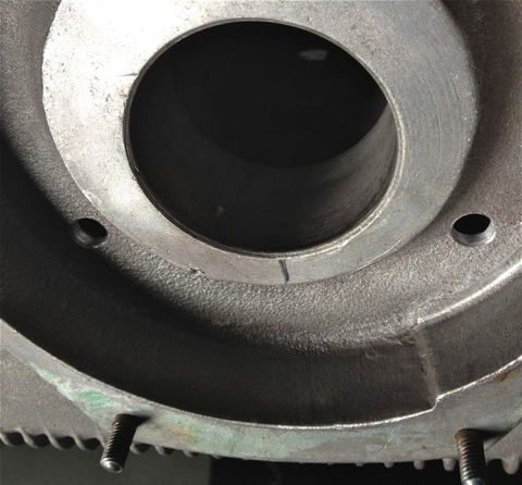
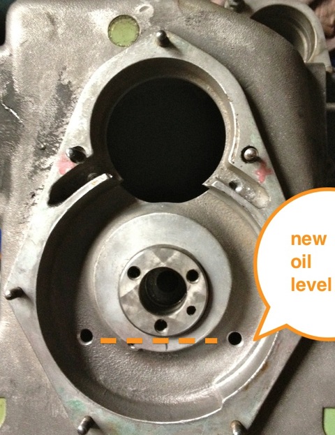
These new drillings, now restore the status quo, and at the same time allow for this area to get some oil changes. Technically these wouldn’t get fully drained, unless the steel timing cover case was removed, because there is no low level return point. I think it is realistic to revise this mod and lower the oil level further, but as this is the third engine I have modded, I will wait until I get some better feedback on the wear characteristics before doing so.
Next up is restore the crankcase oil drilling that originally existed, before Panhard revised it. I need to get a long series drill to do this properly, as the entry angle into the casting, means the drill chuck would catch otherwise.

Normal practice for a splash lubricated gear is to have no more than a third of gear diameter immersed, so why Panhard did this surprises me. Originally they had a fibre wheel of massive proportions meshing to a hardened steel gear, and in all fairness it probably didn’t need much lubrication. Brian’s engine has a dural gear fitted, a specialised aluminium alloy version, that available from most Club sources, and it is made in France.

These new drillings, now restore the status quo, and at the same time allow for this area to get some oil changes. Technically these wouldn’t get fully drained, unless the steel timing cover case was removed, because there is no low level return point. I think it is realistic to revise this mod and lower the oil level further, but as this is the third engine I have modded, I will wait until I get some better feedback on the wear characteristics before doing so.

Next up is restore the crankcase oil drilling that originally existed, before Panhard revised it. I need to get a long series drill to do this properly, as the entry angle into the casting, means the drill chuck would catch otherwise.
Panhard oil pump modification
04/03/12 08:06
The oil pump before
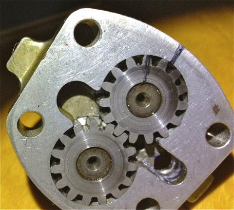
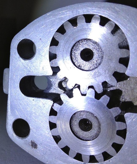
This modified oil pump will now flow more oil at speed, when you want it and there will be less bubbles in the oil as a result, which has the effect of improving the oil quality.
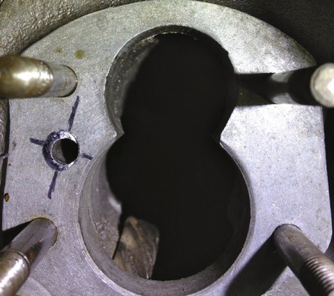
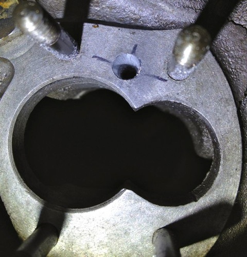
You can see the small inlet pipe into the crankcase, and also see where the oil pump mates up to it, which is the black circle I have inked in and the centre of the outlet is represented by the black lines. So again the flexible shaft is used to reshape this area, and the important thing is to match the mating diameters more closely. It makes sense to machine and open up this drilling to match the oil pump, as this will increase the flow rate into the main oil galleries, and it has no effect on the pressure of the system, contrary to what you might think. The pressure in the unmodified camshaft is controlled by the cross drilling after this, and the cylinder head feeds likewise by the size of their respective openings too. It really doesn’t make sense not to do it.
Next up revising the front crankshaft feed


This modified oil pump will now flow more oil at speed, when you want it and there will be less bubbles in the oil as a result, which has the effect of improving the oil quality.

You can see the small inlet pipe into the crankcase, and also see where the oil pump mates up to it, which is the black circle I have inked in and the centre of the outlet is represented by the black lines. So again the flexible shaft is used to reshape this area, and the important thing is to match the mating diameters more closely. It makes sense to machine and open up this drilling to match the oil pump, as this will increase the flow rate into the main oil galleries, and it has no effect on the pressure of the system, contrary to what you might think. The pressure in the unmodified camshaft is controlled by the cross drilling after this, and the cylinder head feeds likewise by the size of their respective openings too. It really doesn’t make sense not to do it.

Next up revising the front crankshaft feed
Panhard crankcase oil circulation faults (revisited)
03/03/12 12:50
A quick history lesson on Panhard engine failures. The front main bearing and front cylinder crankshaft big end started to develop failures, as they increased the horsepower. It was attributed to insufficient oil supply, and so the front end lubrication was revised, and the camshaft timing gears were used as a splash lubrication system and the oil drilling that provided that role under the front main bearing was removed. This modification was introduced from around the early 1960’s, and ran to the end of production in 1967.
This engine is the later type, so needs modifying back to the original oil supply route, but adding the improvements necessary to negate the other faults. The first area to tackle is the front end crankshaft oil supply, so plugging the newer oil drillings and creating a matched new one under the front main bearing housing. These will be fixed with Loctite once all the drilling has finished and the crankcase has been thoroughly cleaned.
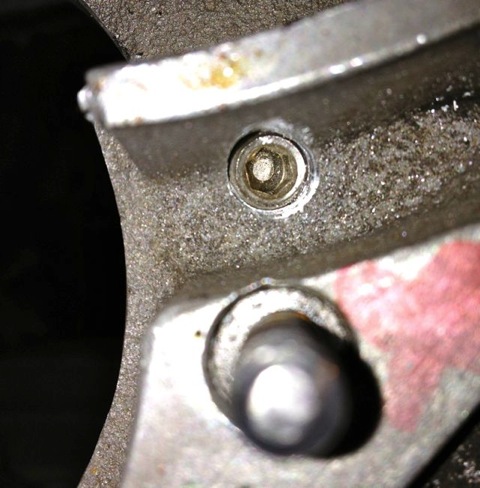
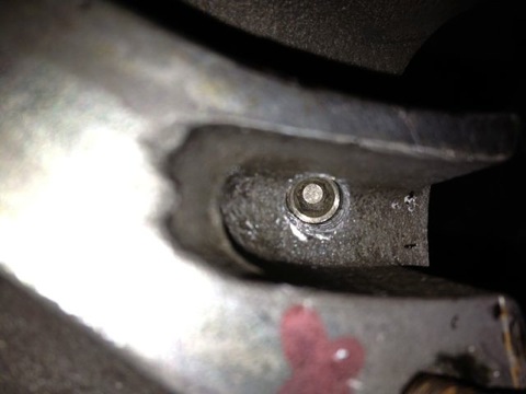
Plugging the timing gear lubrication drilling, so restoring equal phasing, but fitting a new design of oil light piston to replace this function.
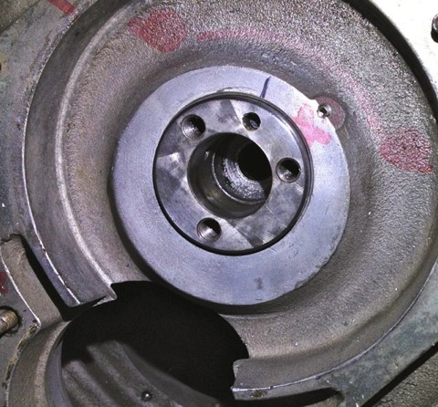
Later I will reduce the oil flow in the timing gear casing, so reduce pump losses, and oil degradation. On examination the deposits in the slingers at the front part of the crankshaft are almost double those at the rear, which is due to the oil supply being much greater and the timing gear casing is a residue trap, because it cannot drain away and be refreshed.
This engine is the later type, so needs modifying back to the original oil supply route, but adding the improvements necessary to negate the other faults. The first area to tackle is the front end crankshaft oil supply, so plugging the newer oil drillings and creating a matched new one under the front main bearing housing. These will be fixed with Loctite once all the drilling has finished and the crankcase has been thoroughly cleaned.


Plugging the timing gear lubrication drilling, so restoring equal phasing, but fitting a new design of oil light piston to replace this function.

Later I will reduce the oil flow in the timing gear casing, so reduce pump losses, and oil degradation. On examination the deposits in the slingers at the front part of the crankshaft are almost double those at the rear, which is due to the oil supply being much greater and the timing gear casing is a residue trap, because it cannot drain away and be refreshed.